Note : Les descriptions sont présentées dans la langue officielle dans laquelle elles ont été soumises.
CA 02646690 2008-09-19
Transtek Document No. FR0620
WO 2007/115622 PCT/EP2007/002001
Clamping device
Technical field of the invention
The invention concerns a clamping device comprising:
- a bolt member with a support head and a shank provided with a threaded
portion,
- a locking clip comprising a base equipped with a through-hole for the
passage of the shank of
the bolt member, and retaining means which are supported by the base so as to
be arranged
vertically to the through-hole and which are suitable for cooperating with the
threaded portion
to effect axial immobilization between the bolt member and the locking clip.
Prior art
Such a device can be used in assembling a plurality of parts by axial
compression, particularly
by bolt and nut clamping. The parts are, for example, planar elements in the
nature of plates,
panels[,] metal sheets or the like. One class of element that has been known
for many years is
pincer-shaped nuts, that is, nuts having the general shape of a U and
essentially comprising a
first branch having a screw socket, connected to a second branch with an
opening for the passage
of a bolt. An example of this type of clamping device is described in the
document FR2754575,
with a nut forming a pincer further comprising an annular portion cut out of a
flap bent back
from the second branch so as to extend between the two branches of the nut and
center it on one
of the planar elements to be assembled.
The known clamping devices are not completely satisfactory, however, since the
retaining means
designed to cooperate with the threaded portion of the shank are in the form
of screw sockets in
which the threads of that portion can engage. To ensure clamping during
assembly. it is therefore
necessary to tighten the bolt member so that it is translated in a helical
movement relative to the
CA 02646690 2008-09-19
Transtek Document No. FR0620
WO 2007/115622 PCT/EP2007/002001
locking clip to effect the desired clamping. The mounting and manipulation
time required for
such assembly is long, especially when the dimensions of the parts to be
assembled necessitate
more than one clamping device. That time is directly related to the length of
the threaded portion
and to the relative arrangement of the parts. The significance of this
drawback is all the greater
since the clamping devices are used in final assembly lines, which are
generally the most cost-
intensive.
In addition, the pull-out strength of the bolt member is relatively low, since
it is directly related
to the mechanical strength of the screw sockets. The latter consist, for
example, of rigid tongues
punched and stamped from the base, whose free ends are rigidly engaged in the
threads of the
threaded portion. When a very high pull-out force is applied to the bolt
member, the tongues will
often deform (axially or radially) irreversibly and will unexpectedly release
the bolt member.
Subject matter of the invention
The object of the invention is to propose a clamping device that is of simple
and inexpensive
design, and which facilitates the assembly operation and increases the
reliability of the assembly
obtained.
This object is achieved according to the invention by the fact that the
retaining means are
constituted by a plurality of flexible and elastic tongues, arranged
convergently such that their
free ends define between them a gap which is smaller than the nominal diameter
of the threaded
portion so that they automatically enter into engagement with the threads of
the threaded portion
when the shank is inserted axially into the through-hole, and by the fact that
a burr directed
toward the flexible tongues is provided at the periphery of the through-hole
to form a stop for the
free ends when the shank is axially withdrawn.
The axial insertion movement of the bolt member in the locking clip spreads
the free ends of the
flexible tongues apart radially. At the end of insertion, the elasticity of
the flexible tongues
automatically causes their free ends to engage with the threads of the
threaded portion to the
ensure retention and axial immobilization of the bolt member relative to the
locking clip. To
4
CA 02646690 2011-09-28
increase the clamping force produced by axial compression, the operator then
need only
tighten the bolt member slightly until a desired tightening torque is reached.
In other
words, assembly is effected, first, merely by exerting axial pressure on the
bolt member
relative to the locking clip, and then, optionally, by tightening the bolt
member slightly.
This feature facilitates assembly by virtue of the fast, simple manipulation
of the bolt
member.
When a pull-out force is applied to the bolt member, the free ends of the
tongues come to
rest against the respective ends of the burr. This deprives the free ends of
the flexible
tongues of their radial and axial mobility. The pull-out strength of the bolt
member,
which gives the clamping device its mechanical strength, is consequently very
high,
which helps to increase the reliability of the assembly.
In a broad aspect, the present invention provides a clamping device
comprising: a bolt
member with a support head and a shank provided with a threaded portion, a
locking clip
comprising a base equipped with a through-hole for the passage of said shank
of said bolt
member, and retaining means which are supported by said base so as to be
arranged
vertically to said through-hole and which are suitable for cooperating with
said. threaded
portion to effect axial immobilization between said bolt member and said
locking clip,
characterized in that said retaining means are formed by a plurality of
flexible and elastic
tongues, arranged convergently such that their free ends define between them a
gap (d)
which is smaller than the nominal diameter of said threaded portion so that
they
automatically enter into engagement with the threads of said threaded portion
when said
shank is inserted axially into said through-hole, and by the fact that a burr
directed toward
said flexible tongues is provided at the periphery of said through-hole to
form a stop for
said free ends when said shank is axially withdrawn, and by the fact that said
connecting
arms are interconnected by at least one stiffener that is parallel to said
base and by the
fact that the opposite ends of said flexible tongues from said free ends are
each integral to
a respective connecting arm connected to said base by an elastically
deformable region.
CA 02646690 2011-01-25
Brief description of the drawings
Other advantages and characteristics will emerge more clearly from the
following
description of particular embodiments of the invention, provided as non-
limitative
examples and depicted in the appended drawings, wherein:
- Fig. 1 is a perspective view of the locking clip in a first exemplary
embodiment of the
clamping device according to the invention,
- Fig. 2 is a longitudinal sectional view of the locking clip from Fig. 1,
- Fig. 3 is a perspective view of the first exemplary clamping device, showing
a planar
element to be assembled and the locking clip in cross section,
- Fig. 4 is a perspective view of the locking clip in a second exemplary
embodiment of
the clamping device according to the invention,
- Fig. 5 is a perspective view of the locking clip in a third exemplary
embodiment of the
clamping device according to the invention,
- Fig. 6 is a perspective view of the locking clip in a fourth exemplary
embodiment of the
clamping device according to the invention.
5a
CA 02646690 2008-09-19
Transtek Document No. FR0620
WO 2007/115622 PCT/EP2007/002001
Description of particular embodiments
Figures 1 to 3 illustrate a first exemplary clamping device according to the
invention, composed
of a locking clip 10 and a bolt member 11. The bolt member 11, which is made
of metal, for
example, and is visible only in Fig. 3, comprises a partially threaded shank
12 and, at the so-
called proximal end, a support head 13. The shank 12 has a smooth upper
portion 14 located
close to the support head 13 and a threaded lower portion 15 extending to the
opposite end,
referred to as the distal end.
In the first embodiment, the locking clip 10 is configured as a straddle
member having the
general shape of a U, with substantially parallel first and second branches
16, 17. The locking
clip 10 is fabricated by being cut from a metal plate and bent.
The clamping device will now be described in a specific but in no way
limitative application
example, consisting of the assembly of planar elements in the nature of
plates, panels, metal
sheets or the like. It goes without saying, however, that the clamping device
can be used more
generally in all applications requiring the use of a bolt and nut type system.
In this application example, one of the planar elements to be assembled,
partially illustrated in
Fig. 3 as reference 18, is designed to be placed between the branches 16, 17
of the locking clip
10. The other planar element or elements of the assembly are not shown.
Branches 16, 17 can
exhibit a slight convergence so that the locking clip 10 can be premounted and
affixed to the
planar element 18 prior to the final assembly operation executed in
cooperation with bolt
member 11.
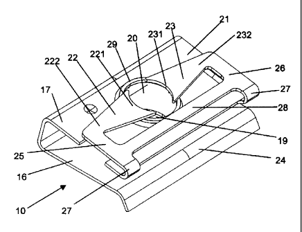
First branch 16 and second branch 17 each have respective through-holes,
referenced 19, 20, for
the passage of the shank 12 of bolt member 11. First branch 16 terminates in
an outwardly bent
portion 24 designed to facilitate the placement of the locking clip 10 on the
planar element 18.
According to the invention, second branch 17 constitutes a base, noted 21,
supporting two
flexible and elastic tongues 22, 23 disposed, relative to the base 21, on the
opposite side from
6
CA 02646690 2008-09-19
Transtek Document No. FR0620
WO 2007/115622 PCT/EP2007/002001
first branch 16. The flexible tongues 22, 23 are arranged to be convergent,
such that their free
ends, respectively referenced 221, 231, are situated vertically to the through-
hole 20 and define
between them a gap, noted d, which is smaller than the nominal diameter of the
threaded portion
15. Each free end 221, 231 presents a circular hollow-out portion whose
diameter corresponds to
the inner diameter of the threading forming threaded portion 15. The opposite
ends 222, 232 of
the flexible tongues 22, 23 from the free ends 22 1, 231 are each integral to
a respective
connecting arm 25, 26 connected to the base 21 by a portion 27 bent back 180 ,
constituting an
elastically deformable region. The connecting arms 25, 26 are perpendicular to
their respective
flexible tongues 22, 23. In the example described, flexible tongues 22, 23 and
connecting arms
25, 26 are therefore coplanar, and are parallel to the base 21. Connecting
arms 25, 26 are
connected to each other by a stiffener 28, which is straight in the example.
When the operator assembles the planar elements using the above-described
clamping device,
the locking clip 10 is first premounted and attached to the planar element 18.
The other planar
element or elements that are to be assembled with element 18 are then
superposed and are
positioned against the first branch 16 or near it, outside the locking clip
10. Each planar element
is provided with an opening designed to be traversed axially by the shank 12.
The planar
elements can each be integral to a respective part of any desired shape, said
parts (not shown)
being designed to be assembled to one another in a region where the planar
elements are
superposed and can be assembled by clamping.
The shank 12 of the bolt member 1 1 is then inserted into the openings in the
planar elements to
be assembled with element 18, proceeding from the distal end toward the
proximal end, then into
through-hole 19, then through planar element 18, then into through-hole 20,
until coming into
contact with the free ends 221, 23I of the flexible tongues 22, 23. The axial
insertion of the
shank 12 into the locking clip 10 then causes the flexible tongues 22, 23 to
flex in such a way
that their free ends 22 1, 23 1 move axially away from through-hole 20 of base
21. Due to the
manner in which flexible tongues 22, 23 are supported on base 21, this flexing
movement of the
flexible tongues 22, 23 is accompanied by spreading of the free ends 221, 231
in the radial
direction, commensurately increasing the gap d. These axial and radial
movements of the free
ends 221, 231, are facilitated and amplified by the presence of deformable
regions constituted by
7
CA 02646690 2008-09-19
Transtek Document No. FR0620
WO 2007/115622 PCT/EP2007/002001
bent portions 27. The stiffener 28 eliminates or at least limits the ability
of connecting arms 25
and 26 to rotate about the axis perpendicular to the plane of the base 21.
At the end of the insertion of the bolt member 11, support head 13 butts
against the relevant
planar element, and the elasticity of the flexible tongues 22, 23
automatically causes their free
ends 221, 231 to engage with the threads of threaded portion 15. More
precisely, the hollowed-
out portions come to bear linearly against the roots of the threads to effect
the retention and axial
immobilization of bolt member 1 I relative to locking clip 10. The profiles of
the flexible tongues
22, 23 at the opposite ends 222, 232 are chosen so that the free ends 221, 23
1 can be made to
rotate by twisting the flexible tongues 22, 23, and thus to orient themselves
to the angle of
inclination of the threads of threaded portion 15. This feature increases the
torque strength of the
locking clip 10.
The axial immobilization serves to clamp planar element 18 together with the
other planar
element or elements, and thus to assemble them. To increase the clamping force
produced by
axial compression, the operator then need only tighten bolt member 1 1
slightly to a desired
tightening torque. In other words, the assembly of the planar elements 18 and
other elements is
performed, first, merely by exerting axial pressure on the bolt member 1 1
relative to the locking
clip 10, and then, optionally, by tightening the bolt member I I slightly.
This feature facilitates
assembly by virtue of the fast, simple manipulation of the bolt member 11.
When a pull-out force is applied to the bolt member 11, the free ends 221, 231
of the flexible
tongues 22, 23 come to rest against the top end of a burr 29 directed toward
the flexible tongues
22, 23 and provided at the periphery of the through-hole 20. The burr 29 thus
forms a stop for the
free ends 221, 231 which deprives them of their radial and axial mobility.
This effect is
amplified by the presence of the stiffener 28. The pull-out strength of the
bolt member 11, which
gives the clamping device its mechanical strength, is consequently very high,
which helps to
increase the reliability of the assembly obtained.
The locking clip 10 and the bolt member 1 1 can be made from other suitable
materials, varying
with the application, such as molded plastic, for example. The number of
flexible tongues 22, 23
8
CA 02646690 2008-09-19
Transtek Document No. FR0620
WO 2007/115622 PCT/EP2007/002001
can also vary with the application, based, for example, on the constituent
material of the locking
clip 10 and/or the desired rigidity during the axial insertion of the bolt
member 11 and/or the
sought pull-out strength.
Figures 4 and 5 respectively illustrate the locking clips 30 and 40 in two
other exemplary
embodiments of the clamping device according to the invention, usable in
different applications.
Locking clip 30 (Fig. 4) differs from locking clip 10 by the fact that first
branch 16 has been
eliminated. The manner of operation of the base 21 and the flexible tongues
22, 23 remains the
same, however. Extending from one edge of the base 21 is a fixing flap 31
suitable for insertion
in a mating receptacle provided in a first part to be clamped against a second
part held in place
by support head 13. The first and second parts are formed, for example, by the
two articulated
half-bores of a pipe clamp.
Locking clip 40 (Fig. 5) differs from locking clip 30 by the fact that the
fixing flap 31 has been
eliminated and the base 21 has larger dimensions in at least one of the
directions, to be able to
accommodate a plurality of fixing holes 41. The fixing holes 41 make it
possible, for example, to
overmold one of the parts to be clamped onto locking clip 40, or to affix the
clip to one of the
parts to be clamped by means of bolts or screws.
Figure 6 illustrates the locking clip 50 in a fourth exemplary embodiment of
the clamping device
according to the invention. Locking clip 50 differs from locking clip 30 by
the fact that the
connecting arms 25, 26 extend beyond their junction with the opposite ends
222, 232 of the
flexible tongues 22, 23. The free ends 251, 261 of the connecting arms, i.e.,
the opposite ends
from those connected to the base 21, are connected to each other by a
stiffener 5 1. The
connecting arms 25, 26 and the stiffeners 28, 51 form a stiffening frame
designed to eliminate
any possibility of radial movement by free ends 221, 231 other than that
caused by the flexion of
flexible tongues 22, 23 during the insertion of bolt member 11. This feature
increases both the
pull-out strength of the bolt member 1 1 and the torque strength of the
locking clip 50.
9