Note : Les descriptions sont présentées dans la langue officielle dans laquelle elles ont été soumises.
CA 02649733 2009-01-14
- I -
SINTERED GEAR
BACKGROUND OF THE INVENTION
1. Field of the invention
The invention relates to a sintered gear with teeth, between which a tooth
base is
respectively formed, as well as a method of producing the sintered gear with
improved
ability to withstand mechanical stress.
2. Prior art
It is becoming increasingly common for components manufactured by means of
conventional molten metallurgical methods to be replaced by components made by
powder
metallurgy, not least because they are easier to produce in more complex
geometries. Due
to the manufacturing method, however, sintered components do not have high
strength
unless treated, due to the residual porosity of these sintered components. In
one respect,
this residual porosity is desired, for example in the case of sintered
components intended
for use in lubricated systems, in which case the pores can be used as
reservoirs for lubri-
cant. Various methods of reducing this residual porosity have already been
proposed in the
prior art as a means of improving ability to withstand mechanical stress, for
example com-
pacting the surface of gears by radial pressing or rolling. To date, however,
treating the
tooth flanks by a surface hardening or surface compaction process with a view
to increas-
ing the ability to withstand mechanical stress as the primary aim has meant
deliberately
reducing hardness in the tooth root region in order to improve mechanical
properties.
For example, patent specification DE 10 03 779 A1 describes case-hardened
gears
subjected to surface pressure and flexing with good strength properties in
terms of flexing
endurance. To this end, the areas subjected to flexing, in other words the
tooth base parts,
have a lower surface hardness or case-hardened depth and the surface hardness
in the tooth
base part is approximately within the range of between 48 and 58 HRc. In order
to produce
these gears, they are firstly case-hardened using a known method and after
hardening,
CA 02649733 2009-01-14
-2-
some of the hardened layer at the tooth base is removed again and is so with a
view to
preserving as uniform a transition as possible of the hardness value from the
tooth base to
the active tooth flank profile, for example by grinding.
Patent specification DE 25 56 170 Al discloses a method of increasing the hard-
ness of hardened and/or heat-treated gears, at least with respect to the tooth
flanks, where-
by the region where the tooth flanks merge into the adjacent tooth base is
rounded. In this
respect, the rounded transition is refined by a surface treatment directed
transversely to the
longitudinal extension of the teeth, for example by grinding and/or polishing.
The intention
is to ensure that the scoring produced by processing extends transversely to
the longitudi-
nal direction of the teeth so that it lies on the teeth in the plane disposed
in the direction in
which forces acts on them and not perpendicular thereto. This reduces fatigue
notch
sensitivity in the tooth base region and increases the bearing capacity of the
gear.
Patent specification DE 11 79 081 Al discloses a method whereby the tooth base
and fillets adjoining the tooth base and the tooth flanks are ground out and
optionally
polished in order to prevent abrasion cracks at the tooth base of gears.
Patent specification DE 29 34 413 Al, finally, discloses a method of simultane-
ously processing the tooth base by grinding in conjunction with gear-grinding
the tooth
flanks.
In the case of sintered gears, the tooth base has not been subjected to such
finish-
ing processes in the past, on the one hand in order to avoid reducing the
surface hardness,
as described in DE 10 03 779 A1 mentioned above, and also to enable the pores
in the
tooth base region to be used as "lubricant pockets".
OBJECTIVES AND ADVANTAGES OF THE INVENTION
The objective of this invention is to improve the ability of a sintered gear
to
withstand mechanical stress.
CA 02649733 2009-01-14
-3-
This objective is achieved by the invention on the basis of a sintered gear
and the
tooth base has a surface which is subjected to a thermo-mechanical finishing
process and
has a surface roughness with an arithmetical mean roughness value Ra, measured
in accor-
dance with DIN EN ISO 4287, which is selected from a range with a lower limit
of 0.2 m
and an upper limit of 2.0 m, and on the basis of a method of producing the
sintered gear
whereby its tooth base is subjected to thermo-mechanical processing until this
surface
roughness is imparted to the tooth base. Surprisingly, it has been found that
subjecting the
tooth base to thermo-mechanical processing improves resistance of the tooth to
breaking
by avoiding abrasive cracks, and in addition, especially in the event of
inadequate cooling
of the processed surface, the thermo-mechanical processing of this surface
also induces
stresses in the tooth base, thereby enabling the internal stress profile in
this region and
hence the ability of a sintered gear to withstand mechanical stress to be
increased. The
strength is therefore higher - than sintered gears not subjected to a
finishing process - by
up to 20 %. Due to the internal stress induced by pressure, it is possible to
achieve levels of
strength close to those which can be obtained from solid material, and in
particular, the gap
between solid steel gears and gears made from sintered materials, which
currently have a
20 % lower mechanical strength, can be reduced by up to 10 %. With the
sintered gear
proposed by the invention, strength levels can be achieved which are
comparable with
those of solid gears, which means that the case width of such sintered gears
can be in-
creased. Thermo-mechanical processing with inadequate cooling likewise leads
to a plasto-
mechanical hardening of the peripheral layer, as a result of which the
porosity in these
peripheral layers can also be reduced. This means that an additional surface
compaction
can be achieved and, generally, that a surface compaction can be applied if
this has not
been done prior to the thermo-mechanical finishing process. This finishing
process also
enables the accuracy of the tooth geometry to be increased, thereby reducing
the play
between mutually meshing gears and hence also improving the acoustic
properties of such
a transmission, i.e. imparting a low noise level. Another advantage is the
fact that due to
"strain hardening", the temperature stress in this surface region is
relatively low, which
means that re-crystallisation does not occur and there is therefore no drop in
stress. With
this method, it also possible to reduce the cost of manufacturing such
sintered gears be-
cause the standard process of irradiating this surface that has been used to
date can be dis-
CA 02649733 2009-01-14
-4-
pensed with. This finishing process also reduces flitter caused by the process
of rolling the
tooth flanks. At the same time, any brittle hard layers can be removed from
the surface if
necessary.
In particular, the surface roughness also has an arithmetical mean roughness
value
Ra, measured in accordance with DIN EN ISO 4287, which is selected from a
range with a
lower limit of 0.6 pm and an upper limit of 1.2 m.
In order to increase mechanical strength and further improve acoustic values,
it is
of advantage if the surface of the tooth base of the sintered gear has a
maximum roughness
profile value R3z, measured in accordance with DBN 31007, which is selected
from a
range with a lower limit of 0.5 m and an upper limit of 8 pm.
In particular, the surface of the tooth base has a maximum roughness profile
value
R3z, measured in accordance with DBN 31007, which is selected from a range
with a
lower limit of 1 m and an upper limit of 5 m.
In terms of improving ability to withstand stress and increasing the service
life of
the sintered gear, it is also of advantage if the tooth base superficially has
at least the same
hardness as the surface of the adjoining tooth flanks and the adjoining
rounded regions of
the transitions to the tooth flanks.
In one embodiment of the sintered gear, the surface of the tooth base has a
residual porosity of at most 12 %. Surprisingly, it has been found that such a
low residual
porosity still assists lubrication of a geared transmission with a sintered
gear proposed by
the invention to a sufficient degree that, in conjunction with the improved
ability to with-
stand mechanical stress, i.e. the strength of the sintered gear, the service
life itself can be
further improved.
In one embodiment of the method proposed by the invention, the thermo-me-
chanical finishing process is conducted with a polishing means which has a
grain size
selected from a range with a lower limit of 50 and an upper limit of 150. With
polishing
CA 02649733 2009-01-14
-5-
means with grain sizes specifically selected from this range, it has been
found that a further
increase can be achieved in the internal stress induced.
In this connection, it is also of advantage if the finishing process is
conducted
with a polishing means with a grain size selected from a range with a lower
limit of 70 and
an upper limit of 110, and has a grain size of 90.
BRIEF DESCRIPTION OF THE DRAWING
To provide a clearer understanding of the invention, it will be explained in
more
detail below with reference to the appended drawing. The drawing
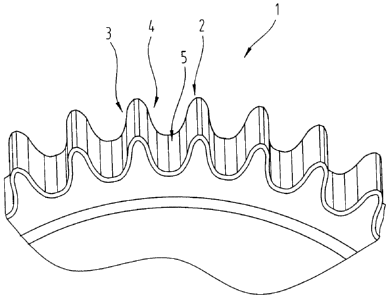
FIG. 1 shows a schematic detail of the toothing region of a sintered gear.
DETAILED DESCRIPTION OF PREFERRED EMBODIMENTS
Firstly, it should be pointed out that the same parts described in the
different em-
bodiments are denoted by the same reference numbers and the same component
names and
the disclosures made throughout the description can be transposed in terms of
meaning to
same parts bearing the same reference numbers or same component names.
Furthermore,
the positions chosen for the purposes of the description, such as top, bottom,
side, etc., re-
late to the drawing specifically being described and can be transposed in
terms of meaning
to a new position when another position is being described. Individual
features or com-
binations of features from the different embodiments illustrated and described
may be
construed as independent inventive solutions or solutions proposed by the
invention in
their own right.
All the figures relating to ranges of values in the description should be
construed
as meaning that they include any and all part-ranges, in which case, for
example, the range
of I to 10 should be understood as including all part-ranges starting from the
lower limit of
CA 02649733 2009-01-14
-6-
1 to the upper limit of 10, i.e. all part-ranges starting with a lower limit
of 1 or more and
ending with an upper limit of 10 or less, e.g. 1 to 1.7, or 3.2 to 8.1 or 5.5
to 10.
Fig. I illustrates a detail of a sintered gear 1. This sintered gear 1 has
teeth
distributed around an external circumference of the sintered gear 1.
The expression sintered gear within the meaning of the invention should be con-
strued as meaning a gear made from a sintered material. Materials which might
specifically
be used for this purpose are aluminium, iron, copper, magnesium, titanium and
alloys
thereof. Examples of such sinter metal alloys may be found in DIN V 30 910
Part 4, page
3. In particular, a sintering steel is used which contains one of the elements
comprising
copper, nickel, manganese, chromium, silicium, molybdenum, vanadium. This
sintering
steel may also contain carbon in a proportion of up to 0.65 % by weight. For
example,
sintering steels of the following composition may be used: carbon 0.2 % by
weight, mag-
nesium < 0.1 % by weight, molybdenum 0,85 % by weight, the rest being iron
with the
impurities induced by the manufacturing process, or carbon 0.3 % by weight,
chromium
1.5 % by weight, molybdenum 0.25 % by weight, the rest being iron with
impurities
induced by the manufacturing process.
Processing aids for the sintered components may be added to these powders,
such
as manganese sulphide.
All the figures given in connection with the composition refer to the finished
alloy.
In order to produce these alloy powders, the individual metals may be mixed
with
one another or alternatively, powders which have already been pre-alloyed may
be used.
Since the skilled person will be familiar with the method used to produce
sintered
components, reference may be made to the relevant background literature. In
particular, the
process of producing sintered components involves the method steps of mixing
the powder,
optionally with additives and agents, such as anti-friction agents or
lubricants for example,
CA 02649733 2009-01-14
-7-
compacting the powder to produce a green compact, sintering the green compact,
and if
necessary calibrating and/or re-compacting the sintered components. Production
may also
include case-hardening or tempering such components.
In a known manner, the teeth 2 each have a left-hand and a right-hand tooth
flank
3, 4 as well as a tooth base 5 adjoining them. The two tooth flanks 3, 4 are
preferably
ground.
For the purpose of the invention, the tooth base 5 is subjected to a thermo-me-
chanical process, in particular by grinding and/or honing. The grinding or
honing takes
place in the axial direction of the sintered gear 1. This produces a surface
roughness of the
sintered gear in the region of the tooth base 5 with an arithmetical mean
roughness value
Ra corresponding to the explanations given above. It is preferable to select a
maximum
roughness profile R3z in the region of the tooth base 5 from the range
specified above.
The two tooth flanks 3, 4 may also have these same values of mean roughness
and
optionally the same roughness profile value.
As illustrated in Fig. 1, the edge in the region of the transition from the
surface of
the teeth in the region of the tooth flank 3, 4 as well as the tooth base 5 to
the surface in the
radial direction of the sintered gear 1 may be stepped, which also enables the
ability of the
sintered gear 1 gear to withstand stress to be increased, and in particular
facilitates engage-
ment for additional meshing of the sintered gear 1.
The following tests were conducted whilst experimenting with the invention.
Example I
An alloy powder of the following composition was used to produce a sintered
gear I as proposed by the invention:
carbon 0.2 % by weight, magnesium < 0.1 % by weight, molybdenum 0.85 % by
CA 02649733 2009-01-14
-8-
weight, the rest being iron with impurities induced by the manufacturing
process.
This alloy powder was compacted at a pressure of 700 MPa to obtain a green
compact and then sintered at a temperature in the range of between 1100 C and
1350 C.
This was followed by a calibration of the sintered gear I with the aid of a
die by pressing it
through the die.
As an alternative to pushing it through the die, the component may be ejected
from the die in the direction in which it was introduced into it.
The resultant sintered gear 1 had a core density of ca. 6.9 g/cm' and a
surface
density greater than 7.4 g/cm'.
It should be pointed out that the entire sintered gear 1 may be of
approximately
the core density if processing a non-compacted material.
Following the surface compaction, i.e. calibration and optionally a thermo-
chemical treatment or hardening, the tooth flanks 3, 4 as well as the tooth
base 5 were
ground with a grinding means with a grain size of 90.
Using the pulsator test on this sintered gear 1, it was found to have a tooth
base
strength of 870 MPa.
By comparison, a sintered gear was produced by all the method steps except
that
of grinding the tooth base 5. In the pulsator test, this comparable gear was
found to have a
tooth base strength of 700 MPa - 750 MPa.
By comparison with this, a gear made from solid steel, in other words manufac-
tured by molten metallurgy, has a tooth base strength of 920 MPa auf.
Example 2
A sintered gear 1 was produced in the same way as explained in connection with
CA 02649733 2009-01-14
-9-
example 1, care being taken to ensure that the surface of the tooth flanks 3,
4 and the tooth
base 5 were of approximately the same hardness. This hardness was between 650
HV0.1
and 870 HV0.1. The pulsator test produced the same ratios as those given in
example 1.
Both the sintered gear 1 based on example 1 and that based on example 2 had a
residual porosity of max. 12 % in the region of the surface of the tooth
flanks 3, 4 and the
tooth base. In particular, the residual porosity in example 1 was 5.1 % and
that based on
example 2 was 4.5 %.
Example 3
Example 1 was essentially repeated and a grinding means with a grain size of
90
was used so that the surface of the tooth base 5 had a max. roughness profile
value R3z,
measured in accordance with DBN 31007, of 4.2 m. The pulsator test produced
the same
ratios as specified in example 1.
Other examples
Example 1 was repeated several times but the surface roughness was varied
within
ranges of 0.2 m to 3.0 m and the max. roughness profile value was varied
within ranges
of 0.3 m to 15 m. Results showed that particularly good ability to withstand
mechanical
stress was obtained in the ranges from 0.2 m to 2.0 m for Ra and from 0.5 m
to 8 m
for R3z.
In addition to increasing strength, the method proposed by the invention has a
side-effect in that toothing errors caused by the manufacturing process can be
at least
largely compensated.
The thermo-mechanical finishing process subjects the surface to a temperature
stress selected from a range with a lower limit of 10 C and an upper limit of
250 C. In
particular, the method is conducted with inadequate or no cooling of the
processed surface,
i.e. the tooth base 5 and/or the tooth flanks 3, 4.
CA 02649733 2009-01-14
- 10-
The embodiment described as an example represents one possible variant of the
sintered gear I and it should be pointed out at this stage that the invention
is not
specifically limited to the variants specifically described, and instead other
variants are
possible, for example spiral gearing, bevel gearing, etc., and these possible
variations lie
within the reach of the person skilled in this technical field given the
disclosed technical
teaching. Accordingly, all conceivable variants which can be obtained by
combining
individual details of the variants described and illustrated are possible and
fall within the
scope of the invention.
For the sake of good order, finally, it should be pointed out that, in order
to
provide a clearer understanding of the structure of the sintered gear 1, it
and its constituent
parts are illustrated to a certain extent out of scale and/or on an enlarged
scale and/or on a
reduced scale.
CA 02649733 2009-01-14
-11-
List of reference numbers
I Sintered gear
2 Tooth
3 Tooth flank
4 Tooth flank
Tooth base