Sélection de la langue

Search

Sommaire du brevet 2654879 

Énoncé de désistement de responsabilité concernant l'information provenant de tiers

Une partie des informations de ce site Web a été fournie par des sources externes. Le gouvernement du Canada n'assume aucune responsabilité concernant la précision, l'actualité ou la fiabilité des informations fournies par les sources externes. Les utilisateurs qui désirent employer cette information devraient consulter directement la source des informations. Le contenu fourni par les sources externes n'est pas assujetti aux exigences sur les langues officielles, la protection des renseignements personnels et l'accessibilité.

Disponibilité de l'Abrégé et des Revendications

L'apparition de différences dans le texte et l'image des Revendications et de l'Abrégé dépend du moment auquel le document est publié. Les textes des Revendications et de l'Abrégé sont affichés :

  • lorsque la demande peut être examinée par le public;
  • lorsque le brevet est émis (délivrance).
(12) Brevet: (11) CA 2654879
(54) Titre français: DISPOSITIF DE PERFUSION SOUS PRESSION ET PROCEDE DE FABRICATION D'UN DISPOSITIF DE PERFUSION SOUS PRESSION
(54) Titre anglais: PRESSURE INFUSION DEVICE AND PROCESS FOR MAKING A PRESSURE INFUSION DEVICE
Statut: Octroyé
Données bibliographiques
(51) Classification internationale des brevets (CIB):
  • A61M 5/142 (2006.01)
  • A61M 5/00 (2006.01)
  • A61M 5/14 (2006.01)
(72) Inventeurs :
  • ROBERTSON, DEBRA K. (Etats-Unis d'Amérique)
  • OLIVERIUS, ANDREW R. (Etats-Unis d'Amérique)
(73) Titulaires :
  • VITAL SIGNS, INC. (Etats-Unis d'Amérique)
(71) Demandeurs :
  • VITAL SIGNS, INC. (Etats-Unis d'Amérique)
(74) Agent: RICHES, MCKENZIE & HERBERT LLP
(74) Co-agent:
(45) Délivré: 2014-08-05
(86) Date de dépôt PCT: 2007-05-25
(87) Mise à la disponibilité du public: 2007-12-21
Requête d'examen: 2012-05-04
Licence disponible: S.O.
(25) Langue des documents déposés: Anglais

Traité de coopération en matière de brevets (PCT): Oui
(86) Numéro de la demande PCT: PCT/US2007/069706
(87) Numéro de publication internationale PCT: WO2007/146579
(85) Entrée nationale: 2008-12-09

(30) Données de priorité de la demande:
Numéro de la demande Pays / territoire Date
11/451,192 Etats-Unis d'Amérique 2006-06-12

Abrégés

Abrégé français

L'invention concerne un dispositif de perfusion sous pression comprenant une poche scellée de matériau souple, pouvant être scellé à chaud comprenant des parties de bord généralement opposées ; une couche de matériau sensiblement transparent comprenant des parties de bord généralement opposées pourvues d'une pluralité d'orifices ; les parties de bord opposées de la poche scellée étant repliées sur les parties de bord opposées de la couche de matériau sensiblement transparent et étant scellées à chaud sur la poche scellée grâce aux orifices. Un procédé permettant de fabriquer un dispositif de perfusion sous pression comprend les étapes de production d'une poche scellée de matériau souple, pouvant être scellé à chaud ayant des parties de bord généralement opposées ; de production d'une couche de matériau sensiblement transparent comprenant des parties de bord généralement opposées ; de repli des parties de bord opposées de la poche scellée sur les parties de bord opposées de la couche de matériau sensiblement transparent et de scellage à chaud des parties de bord repliées sur la poche scellée grâce aux orifices.


Abrégé anglais

A pressure infusion device including a sealed bag of flexible, heat sealable material including generally opposed edge portions; a layer of substantially transparent material including generally opposed edge portions provided with a plurality of holes; the opposed edge portions of the sealed bag are folded over the opposed edge portions of the layer of substantially transparent material and are heat sealed to the sealed bag through the holes. A process for making a pressure infusion device including the steps of providing a sealed bag of flexible, heat-sealable material having generally opposed edge portions; providing a layer of substantially transparent material including generally opposed edge portions; folding the opposed edge portions of the sealed bag over the opposed edge portions of the layer of substantially transparent material and heat sealing the folded edge portions to the sealed bag through the holes.

Revendications

Note : Les revendications sont présentées dans la langue officielle dans laquelle elles ont été soumises.


We claim:
1. Pressure infusion device, comprising:
a sealed bag of flexible, heat-sealable material including generally opposed
edge
portions;
means for pressurizing the interior of said sealed bag;
a pressure gauge in fluid communication with the interior of said sealed bag;
a layer of substantially transparent material including generally opposed edge

portions provided with a plurality of holes;
said opposed edge portions of said sealed bag folded over said opposed edge
portions of said layer of substantially transparent material and heat sealed
to one side of
said layer of substantially transparent material through said holes to mount
said layer of
substantially transparent material to said sealed bag and to provide space
between said
sealed bag and said layer of substantially transparent material for receiving
a flexible,
indicia bearing bag containing infusible liquid; and
said layer of substantially transparent material permitting said indicia to be
seen
and scanned therethrough.
2. The pressure infusion device according to claim 1 wherein said layer of
substantially transparent material includes a top portion provided with means
for
removably mounting said bag of infusible liquid to said layer of substantially
transparent
material and between said layer of substantially transparent material and said
sealed
bag.
3. The pressure infusion device according to claim 2 wherein said layer of
substantially transparent material includes an upper portion provided with a
mounting
hole and wherein said means for removably mounting said bag containing
infusible
liquid to said layer of substantially transparent material comprises a
generally U-shaped
member extending through said mounting hole and including an upwardly
extending leg
residing between said layer of substantially transparent material and said
sealed bag
and to which leg said bag containing infusible liquid can be hooked to
removably mount
6


said bag containing infusible liquid to said layer of substantially
transparent material and
to position said bag containing infusible liquid between said layer of
substantially
transparent material and said sealed bag for pressurization.
4. The pressure infusion device according to claim 1 wherein said layer of
substantially transparent material includes and upper edge portion provided
with an
integrally formed and outwardly extending tab portion provided with a hole for
mounting
said layer of substantially transparent material and thereby said pressure
infusion
device to an I.V. stand.
5. The pressure infusion device according to claim 1 wherein said sealed
bag is comprised of opposed layers of heat-sealable material having opposed
edge
portions heat sealed together.
6. The pressure infusion device according to claim 5 wherein said opposed
layers of heat-sealable material comprise opposed layers of urethane coated
nylon.
7. The pressure infusion device according to claim 1 wherein said layer of
substantially transparent material is a layer of substantially transparent
vinyl film.
8. The pressure infusion device according to claim 1 wherein said layer of
substantially transparent material is a layer of substantially transparent
cast nylon.
9. The pressure infusion device according to claim 1 wherein said pressure
gauge is mounted to said sealed bag and includes an internal portion residing
interiorly
of said sealed bag for exposure to the pressure in said sealed bag and an
external
portion residing exteriorly of said sealed bag and including an indicator for
indicating the
pressure in said sealed bag.
10. The pressure infusion device according to claim 1 wherein said means
for
pressurizing the interior of said sealed bag includes a squeeze bulb and a
length of
7


tubing mounted to said squeeze bulb and said sealed bag and for placing said
squeeze
bulb in fluid communication with the interior of said sealed bag.
11. The pressure infusion device according to claim 10 wherein said
pressure
gauge is mounted to said tubing and in fluid communication with the interior
of, and
exposed to the pressure in, said sealed bag through said tubing.
12. The pressure infusion device according to claim 1 wherein said
plurality of
holes are disposed in two spaced apart, generally parallel, straight rows of
holes.
13. Pressure infusion device, comprising:
a sealed bag of flexible, heat sealable material including generally opposed
edge
portions;
a layer of substantially transparent material including generally opposed edge

portions provided with a plurality of holes; and
said opposed edge portions of said sealed bag folded over said opposed edge
portions of said layer of substantially transparent material and heat sealed
to one side of
said layer of substantially transparent material through said plurality of
holes to mount
said layer of substantially transparent material to said sealed bag.
14. The pressure infusion device according to claim 13 wherein said
plurality
of holes are disposed in two spaced apart, substantially parallel straight
rows of holes.
15. The process of manufacturing a pressure infusion device, comprising the
steps of:
providing a sealed bag of flexible, heat sealable material having generally
opposed edge portions;
providing a layer of substantially transparent material including generally
opposed edge portions;
providing said opposed edge portions of said layer of substantially
transparent
material with a plurality of holes;
8


folding said opposed edge portions of said sealed bag over said opposed edge
portions of said layer of substantially transparent material to provide folded
edge
portions of said sealed bag; and
heat sealing said folded edge portions to one side of said layer of
substantially
transparent material through said holes.
16. The process according to claim 15 wherein said step of providing said
sealed bag comprises the steps of providing two layers of heat-sealable
material and
heat-sealing the opposed edge portions of said layers of heat-sealable
material
together.
17. The process according to claim 15 wherein said step of providing said
layer of substantially transparent material is the step of providing a layer
of substantially
transparent vinyl film.
18. The process according to claim 15 wherein said step of providing said
layer of substantially transparent material is the step of providing a layer
if substantially
transparent cast nylon.
19. The process according to claim 15 wherein said step of providing said
opposed edges of said layer of substantially transparent material with a
plurality of holes
is the step of providing said opposed edges of said layer of substantially
transparent
material with two spaced apart, generally parallel, straight rows of holes.
9

Description

Note : Les descriptions sont présentées dans la langue officielle dans laquelle elles ont été soumises.

CA 02654879 2014-01-14
PRESSURE INFUSION DEVICE AND PROCESS FOR MAKING A PRESSURE
INFUSION DEVICE
BACKGROUND OF THE INVENTION
This invention relates to a pressure infusion device for infusing a patient
with a
liquid, such as saline solution, blood, plasma, contained in a flexible bag,
typically
through the use of an I.V. needle. The infusion device applies pressure to the
bag,
typically made of plastic and commonly called an I.V. bag, to collapse the
bag,
pressurize the liquid and cause it flow into the patient.
A pressure infusion device is disclosed in US Patent 4,090,514 issued May 23,
1978, Howard Helmut Hinck, et al. inventors, and also is disclosed in US
Patent
4,735,613, issued Apr. 5, 1988, Matthew E. BeIlin et al. inventors.
SUMMARY OF THE INVENTION
A pressure infusion device including a sealed bag of flexible, heat sealable
material including generally opposed edge portions; a layer of substantially
transparent material including generally oppose edge portions provided with a
plurality of holes; the opposed edge portions of the sealed bag are folded
over the
opposed edge portions of the layer of substantially transparent material and
are heat
sealed to the sealed bag through the holes.
A process for making a pressure infusion device including the steps of
providing a sealed bag of flexible, heat-sealable material having generally
opposed
edge portions; providing a layer of substantially transparent material
including
generally opposed edge portions; folding the opposed edge portions of the
sealed
bag over the opposed edge portions of the layer of substantially transparent
material
and heat sealing the folded edge portions to the sealed bag through the holes.
As such, in one aspect the present invention resides in a pressure infusion
device, comprising: a sealed bag of flexible, heat-sealable material including

generally opposed edge portions; means for pressurizing the interior of said
sealed
bag; a pressure gauge in fluid communication with the interior of said sealed
bag; a
layer of substantially transparent material including generally opposed edge
portions
1

CA 02654879 2014-01-14
provided with a plurality of holes; said opposed edge portions of said sealed
bag
folded over said opposed edge portions of said layer of substantially
transparent
material and heat sealed to one side of said layer of substantially
transparent
material through said holes to mount said layer of substantially transparent
material
to said sealed bag and to provide space between said sealed bag and said layer
of
substantially transparent material for receiving a flexible, indicia bearing
bag
containing infusible liquid; and said layer of substantially transparent
material
permitting said indicia to be seen and scanned therethrough.
In another aspect, the present invention resides in the process of
manufacturing a pressure infusion device, comprising the steps of: providing a
sealed
bag of flexible, heat sealable material having generally opposed edge
portions;
providing a layer of substantially transparent material including generally
opposed
edge portions; providing said opposed edge portions of said layer of
substantially
transparent material with a plurality of holes; folding said opposed edge
portions of
said sealed bag over said opposed edge portions of said layer of substantially

transparent material to provide folded edge portions of said sealed bag; and
heat
sealing said folded edge portions to one side of said layer of substantially
transparent
material through said holes.
DESCRIPTION OF THE DRAWINGS
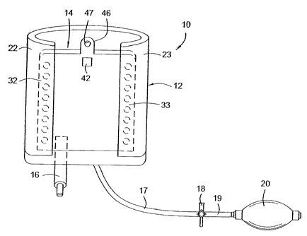
FIG. 1 shows a pressure infusion device of the present invention including a
sealed bag of flexible, heat-sealable material and a layer of substantially
transparent material mounted to the bag;
FIG. 2 shows a separate view of the sealed bag of FIG. 1;
FIG. 3 shows a separate view of the layer of substantially transparent
material
of FIG. 1;
FIG. 4 is a cross-sectional view taken generally along the line 4-4 in FIG. 3
in
the direction of the arrows and including a generally U-shaped mounting, or
hook,
member;
FIG. 5 is a view similar to FIG. 4 but with the mounting member removed;
FIG. 6 is a separate view of the mounting member in perspective;
2

CA 02654879 2014-01-14
=
FIG. 7 is a diagrammatical front view of a flexible bag containing infusible
liquid; and
FIG. 8 is a diagrammatical cross-sectional view of the flexible bag of FIG. 7
shown mounted in the pressure infusion device of FIG. 1.
DETAILED DESCRIPTION OF THE INVENTION
An embodiment of the pressure infusion device of the present invention is
shown in FIG. 1 and is indicated by general numerical designation 10. The
pressure
infusion device 10 includes a sealed bag of flexible, heat-sealable material
indicated
by general numerical designation 12 and a layer of generally transparent
material
indicated by general numerical designation 14 mounted to the bag 12 as
described
below and in accordance with the process for making a pressure infusion device
of
the present invention.
The bag 12 is sometimes referred to in the art as a pressure bag such as the
pressure bag 12 shown in FIG. 1 of United States Patent No. 4,735,613. The bag
12,
FIGS. 1 and 2, may further include a pressure gauge 16, an inlet tube 17, a
valve 18,
a tube 19 and a squeeze bulb 20. The pressure gauge 16 may have the same
structure as the pressure gauge 40 shown in FIGS. 1 and 4-7 of United States
Patent
No. 4,735,613 and will be understood to perform the same function as the gauge
40.
Similarly, the tube 17, valve 18, tube 19 and squeeze bulb 20 of FIGS. 1 and 2
may
have the same structure and perform the same functions as the tube 21, valve
22,
tube 23 and bulb pump 24 shown in FIGS. 1 and 2 of United States Patent No.
4,735,613; more particularly the valve 18 of FIGS. 1 and 2 may have the same
structure as the valve 22 as shown in solid outline in FIG. 1, and in cross-
section in
FIG. 3, of United States Patent No. 4,735,613. Alternative to the pressure
gauge 16,
the pressure infusion device 10 of the present invention may include the
external
pressure gauge 32 shown in FIGS. 1 and 2 of United States Patent No.
4,090,514.
As will be understood from FIG. 2, the bag 12 includes generally opposed
edge portions 22 and 23 which are indicated diagrammatically as being the
opposed
edge portions bounded by the opposed edges 24 and 25 of the bag 12 and the
dashed vertical lines 26 and 27. The layer of substantially transparent
material 14,
3

CA 02654879 2014-01-14
=
FIG. 3, also includes generally opposed edge portions 32 and 33 which are
indicated
diagrammatically as being the opposed edge portions bounded by the opposed
edges 34 and 35 of the layer of substantially transparent material 14 and the
vertical
lines 36 and 37. The opposed edge portions 32 and 33 are provided with a
plurality
of holes 38 which, as shown in FIG. 3, may be disposed in two spaced apart,
generally parallel, straight rows of holes.
Further, the layer of substantially transparent material 14, FIGS. 3-5, may be

provided with a mounting hole 40 at its upper or top portion, note
particularly FIG. 5,
for receiving a generally U-shaped mounting member 42, shown in FIG. 4, which
includes an upwardly extending leg 43 which resides between the layer of
substantially transparent material 14 and the bag 12 as shown in FIG. 8. The
leg 43
is for removably mounting a flexible bag containing infusible liquid, such as
the
flexible bag 45 shown in FIG. 7 containing the infusible liquid 48, in the
pressure
diffusion device of FIG. 1, and more particularly between the layer of
substantially
transparent material 14 and the bag 12, of FIGS. 1 and 2, for pressurization
of the
bag 45 and the infusible liquid 48 to cause the pressurized liquid to flow
through the
tube 50 (FIGS. 7 and 8) and, for example, through the I.V. needle 51 to infuse
a
patient with the liquid. As will be understood from FIG. 7 the flexible bag 45

containing the infusible liquid 48 is provided at its top with a hole or
opening 49
through which the leg 43 of the mounting member 42 (FIGS. 4 and 6,) may be
inserted to removably hook the bag 45 containing the infusible liquid 48 to
the
mounting member 42. Additionally, and referring further to FIG. 3, the layer
of
substantially transparent material 14 may be provided with an integrally
formed and
upwardly extending tab portion 46 provided with a hole 47 through the hook 52
(note
FIG. 8) of an I.V. stand (not shown in its entirety) may be inserted to mount
the
pressure infusion bag 10 of the present invention as a patient is being
infused.
With regard to the mounting of the layer of substantially transparent material

14 to the bag 12, and referring gain to FIG. 1, and in accordance with the
process of
the present invention for making a pressure infusion bag, the opposed edge
portions
22 and 23 of the sealed bag of flexible, heat sealable material 12 are folded
over the
opposed edge portions 32 and 33 of the layer of substantially transparent
material 14
4

CA 02654879 2014-01-14
to provide folded edge portions and such folded edge portions are heat sealed
to the
bag 12 through the holes 38 provided in layer of material 14 thereby mounting
the
layer of substantially transparent material 14 to the bag 12.
The process for making a pressure infusion of the present invention includes
the steps of providing a sealed bag of flexible, heat sealable material having

generally opposed edge portions; providing a layer of substantially
transparent
material including generally opposed edge portions; providing the opposed edge

portions of the layer of substantially transparent material with a plurality
of holes;
folding the opposed edge portions of the sealed bag over the opposed edge
portions
of the layer of substantially transparent material to provide folded edge
portions of
the sealed bag; and heat sealing the folded edge portions to the sealed bag
through
the holes.
The sealed bag 13 of flexible, heat-sealable material may be from two layers
of suitable heat-sealable material, such as for example, urethane coated
nylon, with
their opposed edge portions heat-sealed together. The layer of substantially
transparent material 14 may be a suitable layer of at least substantially,
transparent
plastic film, such as for example, a layer of substantially transparent vinyl
film
available from the Wiman Corporation of Sauk Rapids, MN 56379, and sold as
Product # 1400; alternatively, the layer of at least substantially transparent
material
14 may be a suitable commercially available layer of at least substantially
transparent
cast nylon.
The transparency, or at least substantially transparency, of the layer of
material 14 permits, for example, a barcode or other indicia, imprinted in the
flexible
bag 45 containing the infusible liquid 48 (FIG. 7) to be seen and scanned
through the
layer of material 14.
It will be understood that many variations and modifications of the present
invention may be made without departing from the scope of the present
invention.

Dessin représentatif
Une figure unique qui représente un dessin illustrant l'invention.
États administratifs

Pour une meilleure compréhension de l'état de la demande ou brevet qui figure sur cette page, la rubrique Mise en garde , et les descriptions de Brevet , États administratifs , Taxes périodiques et Historique des paiements devraient être consultées.

États administratifs

Titre Date
Date de délivrance prévu 2014-08-05
(86) Date de dépôt PCT 2007-05-25
(87) Date de publication PCT 2007-12-21
(85) Entrée nationale 2008-12-09
Requête d'examen 2012-05-04
(45) Délivré 2014-08-05

Historique d'abandonnement

Il n'y a pas d'historique d'abandonnement

Taxes périodiques

Dernier paiement au montant de 624,00 $ a été reçu le 2024-04-18


 Montants des taxes pour le maintien en état à venir

Description Date Montant
Prochain paiement si taxe générale 2025-05-26 624,00 $
Prochain paiement si taxe applicable aux petites entités 2025-05-26 253,00 $

Avis : Si le paiement en totalité n'a pas été reçu au plus tard à la date indiquée, une taxe supplémentaire peut être imposée, soit une des taxes suivantes :

  • taxe de rétablissement ;
  • taxe pour paiement en souffrance ; ou
  • taxe additionnelle pour le renversement d'une péremption réputée.

Les taxes sur les brevets sont ajustées au 1er janvier de chaque année. Les montants ci-dessus sont les montants actuels s'ils sont reçus au plus tard le 31 décembre de l'année en cours.
Veuillez vous référer à la page web des taxes sur les brevets de l'OPIC pour voir tous les montants actuels des taxes.

Historique des paiements

Type de taxes Anniversaire Échéance Montant payé Date payée
Enregistrement de documents 100,00 $ 2008-12-09
Le dépôt d'une demande de brevet 400,00 $ 2008-12-09
Taxe de maintien en état - Demande - nouvelle loi 2 2009-05-25 100,00 $ 2009-05-07
Taxe de maintien en état - Demande - nouvelle loi 3 2010-05-25 100,00 $ 2010-05-05
Taxe de maintien en état - Demande - nouvelle loi 4 2011-05-25 100,00 $ 2011-05-04
Enregistrement de documents 100,00 $ 2011-06-13
Taxe de maintien en état - Demande - nouvelle loi 5 2012-05-25 200,00 $ 2012-05-03
Requête d'examen 800,00 $ 2012-05-04
Taxe de maintien en état - Demande - nouvelle loi 6 2013-05-27 200,00 $ 2013-05-03
Enregistrement de documents 100,00 $ 2013-10-31
Taxe de maintien en état - Demande - nouvelle loi 7 2014-05-26 200,00 $ 2014-05-09
Taxe finale 300,00 $ 2014-05-28
Taxe de maintien en état - brevet - nouvelle loi 8 2015-05-25 200,00 $ 2015-04-29
Taxe de maintien en état - brevet - nouvelle loi 9 2016-05-25 200,00 $ 2016-04-22
Taxe de maintien en état - brevet - nouvelle loi 10 2017-05-25 250,00 $ 2017-04-20
Taxe de maintien en état - brevet - nouvelle loi 11 2018-05-25 250,00 $ 2018-04-19
Taxe de maintien en état - brevet - nouvelle loi 12 2019-05-27 250,00 $ 2019-04-19
Taxe de maintien en état - brevet - nouvelle loi 13 2020-05-25 250,00 $ 2020-05-13
Taxe de maintien en état - brevet - nouvelle loi 14 2021-05-25 255,00 $ 2021-05-11
Taxe de maintien en état - brevet - nouvelle loi 15 2022-05-25 458,08 $ 2022-05-11
Taxe de maintien en état - brevet - nouvelle loi 16 2023-05-25 473,65 $ 2023-05-11
Taxe de maintien en état - brevet - nouvelle loi 17 2024-05-27 624,00 $ 2024-04-18
Titulaires au dossier

Les titulaires actuels et antérieures au dossier sont affichés en ordre alphabétique.

Titulaires actuels au dossier
VITAL SIGNS, INC.
Titulaires antérieures au dossier
GENERAL ELECTRIC COMPANY
OLIVERIUS, ANDREW R.
ROBERTSON, DEBRA K.
VITAL SIGNS, INC.
Les propriétaires antérieurs qui ne figurent pas dans la liste des « Propriétaires au dossier » apparaîtront dans d'autres documents au dossier.
Documents

Pour visionner les fichiers sélectionnés, entrer le code reCAPTCHA :


Pour visualiser une image, cliquer sur un lien dans la colonne description du document. Pour télécharger l'image (les images), cliquer l'une ou plusieurs cases à cocher dans la première colonne et ensuite cliquer sur le bouton "Télécharger sélection en format PDF (archive Zip)" ou le bouton "Télécharger sélection (en un fichier PDF fusionné)".

Liste des documents de brevet publiés et non publiés sur la BDBC .

Si vous avez des difficultés à accéder au contenu, veuillez communiquer avec le Centre de services à la clientèle au 1-866-997-1936, ou envoyer un courriel au Centre de service à la clientèle de l'OPIC.


Description du
Document 
Date
(yyyy-mm-dd) 
Nombre de pages   Taille de l'image (Ko) 
Dessins représentatifs 2009-04-03 1 7
Dessins 2008-12-09 5 61
Revendications 2008-12-09 4 154
Abrégé 2008-12-09 1 69
Description 2008-12-09 5 209
Page couverture 2009-04-21 2 50
Description 2014-01-14 5 258
Revendications 2014-01-14 4 162
Dessins 2014-01-14 5 85
Dessins représentatifs 2014-07-14 1 8
Page couverture 2014-07-14 1 46
PCT 2008-12-09 2 81
Cession 2008-12-09 9 298
Taxes 2009-05-07 1 53
Taxes 2010-05-05 1 52
Taxes 2011-05-04 1 52
Cession 2011-06-13 4 134
Poursuite-Amendment 2012-05-04 1 55
Taxes 2012-05-03 1 53
Taxes 2013-05-03 1 52
Poursuite-Amendment 2013-07-16 3 103
Cession 2013-10-31 3 164
Poursuite-Amendment 2014-01-14 24 917
Taxes 2014-05-09 1 53
Correspondance 2014-05-28 1 56