Sélection de la langue

Search

Sommaire du brevet 2657299 

Énoncé de désistement de responsabilité concernant l'information provenant de tiers

Une partie des informations de ce site Web a été fournie par des sources externes. Le gouvernement du Canada n'assume aucune responsabilité concernant la précision, l'actualité ou la fiabilité des informations fournies par les sources externes. Les utilisateurs qui désirent employer cette information devraient consulter directement la source des informations. Le contenu fourni par les sources externes n'est pas assujetti aux exigences sur les langues officielles, la protection des renseignements personnels et l'accessibilité.

Disponibilité de l'Abrégé et des Revendications

L'apparition de différences dans le texte et l'image des Revendications et de l'Abrégé dépend du moment auquel le document est publié. Les textes des Revendications et de l'Abrégé sont affichés :

  • lorsque la demande peut être examinée par le public;
  • lorsque le brevet est émis (délivrance).
(12) Brevet: (11) CA 2657299
(54) Titre français: ELEMENT DE RETENUE ET D'ALIGNEMENT D'ENSEMBLE DE FIXATION
(54) Titre anglais: FASTENER ASSEMBLY RETENTION AND ALIGNMENT ELEMENT
Statut: Octroyé
Données bibliographiques
(51) Classification internationale des brevets (CIB):
  • F16B 43/00 (2006.01)
  • F16B 13/00 (2006.01)
  • F16B 19/02 (2006.01)
  • F16B 27/00 (2006.01)
  • F16B 35/02 (2006.01)
(72) Inventeurs :
  • SESSA, EUGENE (Etats-Unis d'Amérique)
(73) Titulaires :
  • NYLOK CORPORATION (Etats-Unis d'Amérique)
(71) Demandeurs :
  • NYLOK CORPORATION (Etats-Unis d'Amérique)
(74) Agent: FINLAYSON & SINGLEHURST
(74) Co-agent:
(45) Délivré: 2017-08-15
(22) Date de dépôt: 2009-03-06
(41) Mise à la disponibilité du public: 2009-09-17
Requête d'examen: 2014-02-28
Licence disponible: S.O.
(25) Langue des documents déposés: Anglais

Traité de coopération en matière de brevets (PCT): Non

(30) Données de priorité de la demande:
Numéro de la demande Pays / territoire Date
12/077,191 Etats-Unis d'Amérique 2008-03-17

Abrégés

Abrégé français

Un ensemble de fixation comprend un élément de retenue et dalignement utilisé en association avec un premier composant qui possède une paroi cylindrique qui définit un alésage et un second composant qui possède un arbre allongé pour une insertion dans lalésage du premier composant. Lélément de retenue et dalignement comprend une pluralité de protubérances polymères allongées, possédant chacune (i) une base fixée à la paroi cylindrique du premier composant, (ii) une hauteur suffisante pour quensemble, les extrémités libres des protubérances définissent un passage qui crée un réglage avec serrage avec larbre du second composant, et (iii) une longueur suffisante pour maintenir larbre du second composant généralement colinéaire avec laxe de lalésage du premier composant.


Abrégé anglais

A fastener assembly including a retention and alignment element used in combination with a first component having a cylindrical wall defining a bore and a second component having an elongated shaft for insertion into the bore of the first component. The retention and alignment element comprises a plurality of elongated polymeric protuberances, each having (i) a base fixed to the cylindrical wall of the first component, (ii) a height sufficient so that together the free ends of the protuberances define a passageway that creates an interference fit with the shaft of the second component, and (iii) a length sufficient to maintain the shaft of the second component generally collinear with the axis of the bore of the first component.

Revendications

Note : Les revendications sont présentées dans la langue officielle dans laquelle elles ont été soumises.


WHAT IS CLAIMED IS:
1. A fastener assembly including a retention and alignment element used in
combination
with a first component having a cylindrical wall defining a bore and a second
component
having an elongated shaft for insertion into the bore of the first component,
the retention and
alignment element comprising:
a plurality of elongated polymeric protuberances applied to the first
component by
directing an airborne resin powder stream to the cylindircal wall and curing
the resin thereon,
each protuberance having (i) a base adhered to the cylindrical wall along the
entire length of
the protuberance, (ii) a height so that together the free ends of the
protuberances define a
passageway that creates an interference fit with the shaft of the second
component and the free
ends of the protuberances engage the shaft of the second component along
substantially the
entire length of the protuberances, and (iii) a length to maintain the shaft
of the second
component substantially collinear with the axis of the bore of the component.
2. The fastener assembly of claim 1 wherein the polymeric protuberances are
comprised
of an elastomeric resin and a blowing agent so that upon curing the
protuberances exhibit a cell
structure and a degree of elasticity to permit deformation upon assembly of
the two
components.
3. The fastener assembly of claim 1 wherein the first component comprises a
cylinder with
a longitudinal slot extending from one end to the other.
4. A fastener assembly comprising:
a first cylindrical component having a cylinder wall defining a bore and a
slot in the
cylinder wall thereby permitting resilient compression or expansion of the
cylindrical
component;
a second component having a shaft for insertion into the bore of the first
component;
8

a retention and alignment element comprising a coating of polymeric material
adhered
to over fifty percent of the inside of the cylinder wall, the coating being
applied as an airborne
resin powder stream directed to the cylindircal wall and cured thereon, the
coating having a
thickness to establish an interference fit with the shaft of the second
component and an axial
length to maintain the shaft of the second component substantially collinear
with the axis of
the bore of the first component.
9

Description

Note : Les descriptions sont présentées dans la langue officielle dans laquelle elles ont été soumises.

CA 02657299 2016-08-26
FASTENER ASSEMBLY RETENTION AND ALIGNMENT ELEMENT
Background of the Invention
The present invention relates generally to fastener assemblies. More
particularly, the
invention relates to assemblies having one component with a bore or aperture
into which a
second component having a shaft in the form of a stud, rivet, bolt or screw is
inserted and
retained and aligned by means of a unique retention element.
It has been well known in the art to use a retention element in combination
with a collar
or bushing and a bolt or other shaft-like component to maintain the two
components in
assembled relation during storage, shipment and/or other pre-final assembly
operations.
Examples of such prior art devices are shown in United States Patent Nos.
4,399,166 and
6,025,019. Such retention devices, however, may offset the shaft of the
inserted component or
are otherwise ill suited to maintaining the inserted component in concentric
alignment with the
outer component. A retention element having this additional alignment
capability finds
advantageous application in automated manufacturing processes where it is
necessary to more
precisely position the inserted component during various assembly operations.
1

CA 02657299 2016-08-26
Summary of the Invention
In a broad aspect, the invention pertains to a fastener assembly including a
retention and alignment element used in combination with a first component
having a
cylindrical wall defining a bore, and a second component having an elongated
shaft for
insertion into the bore of the first component. The retention and alignment
element
comprise a plurality of elongated polymeric protuberances applied to the first
component
by directing an airborne resin powder stream to the cylindircal wall and
curing the resin
thereon. Each protuberance has (i) a base adhered to the cylindrical wall
along the entire
length of the protuberance. (ii) a height so that together the free ends of
the
protuberances define a passageway that creates an interference fit with the
shaft of the
second component and the free ends of the protuberances engage the shaft of
the second
component along substantially the entire length of the protuberances, and
(iii) a length
to maintain the shaft of the second component substantially collinear with the
axis of the
bore of the component.
2

CA 02657299 2016-08-26
In a further aspect, the invention provides a fastener assembly comprising a
first
cylindrical component having a cylinder wall defining a bore and a slot in the
cylinder
wall, thereby permitting resilient compression or expansion of the cylindrical
component.
A second component has a shaft for insertion into the bore of the first
component. A
retention and alignment element comprise a coating of polymeric material
adhered to
over fifty percent of the inside of the cylinder wall. The coating is applied
as an
airborne resin powder stream directed to the cylindircal wall and cured
thereon, the
coating having a thickness to establish an interference fit with the shaft of
the second
component and an axial length to maintain the shaft of the second component
substantially collinear with the axis of the bore of the first component.
3

CA 02657299 2009-03-06
BRIEF DESCRIPTION OF THE DRAWINGS
The novel features which are characteristic of the present invention are set
forth in
the appended claims. However, the invention's preferred embodiments, together
with
further objects and attendant advantages, will be best understood by reference
to the
following detailed description taken in connection with the accompanying
drawings in
which:
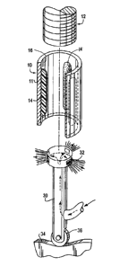
Figure 1 is an exploded perspective view of one embodiment of the invention,
with
portions broken away for clarity of illustration and also showing apparatus
useful in the
construction of the embodiment:
Figure 1A is an end view of the embodiment illustrated in Figure 1:
Figure 2 is also an exploded perspective view showing another embodiment of
the
invention and apparatus useful in its construction: and
Figure 2A is an end view of the embodiment illustrated in Figure 2.
4
=
=

CA 02657299 2009-03-06
Detailed Description of the Preferred Embodiments
With reference to Figures 1 and 1A, a preferred fastener assembly embodiment
in
accordance with the invention is illustrated having a first component 10, a
second component 12
and a retention and alignment element in the form of three protuberances 14.
The first
component is shown in this embodiment as a bushing having a cylindrical wall
11 defining a
bore 13. The second component is shown as a threaded bolt, although any number
of structures
having a shaft sized to permit insertion into the first component 10 may be
employed. The
protuberances 14 have a base 18 fixedly secured.to the inner surface of wall
11 and a free end 20.
The protuberances 14 have a height "X" such that the free ends 20 of the
protuberances define a
passageway (depicted by the phantom line 22) that will establish a press fit
between the two
components when assembled. In this manner, the protuberances will retain the
inserted
component 12 within the first component 10 during storage, shipping or other
handling or
processing operations prior to final assembly in a finished product. In
addition, at least three
protuberances may be employed which are arranged around the circumference of
wall 11 and
have a length sufficient to maintain the inserted component 12 in generally
concentric relation to
the first component. In other words, the shaft of component 12 will be
maintained in generally
collinear relation to the axis of the bore in component 10.
This arrangement of the retention and alignment element will help to properly
position
the shaft of component 12 for subsequent assembly operations where, for
example, a robotic
assembler will be used to join or connect this assembly to other parts or
assemblies of a larger
article of manufacture.
In the fabrication of the embodiment shown in Figures land IA, an air borne
powder
stream is delivered to the inner surface of the wall 11 by means of a nozzle
30 with three

CA 02657299 2015-10-06
discharge ports 32. The powder applied via nozzle 30 is a particulate
thermoplastic resin
blended with a blowing agent such as that disclosed in United States Patent
No. 6,025,019
whose disclosure may be referred to for further details. Importantly, the
melting temperature
of the thermoplastic resin is lower than the activating temperature of the
blowing agent. In
accordance with the present invention, the wall 11 is preheated in advance of
the powder
application step to a temperature above the resin melting temperature, but
below the activation
temperature of the blowing agent. As shown in Figure 1, the nozzle is designed
in a manner
to permit its axial movement within bore 13 as the powder mixture is applied.
This can be
accomplished in any number of ways, for example using a cam 34 and cam
follower 36 to
drive the nozzle 30 along the axial extent of the bore 13 necessary to define
the appropriate
length of the protuberances 14. As the powder mixture is applied to the inner
surface of
preheated wall 11, it melts and adheres to the wall surface. Subsequently, and
after the nozzle
30 has been retracted from bore 13, the component 10 is heated further to
raise the temperature
of the melted powder mixture above the activation temperature of the blowing
agent. This
causes a foaming action to occur and raises the protuberances to the desired
height "X"
necessary to establish a press fit between the two components for the
particular assembly. This
sequence of processing steps allows the nozzle 30 to be easily inserted and
withdrawn from
bore 13 while still achieving a substantial height to the protuberances 14.
The three
protuberances in the illustrated embodiment are positioned at equally spaced
locations about
the circumference of the inner surface of wall 11, but other numbers and
arrangements may
be useful with other component designs.
Figures 2 and 2A illustrate another embodiment of the invention. In this
embodiment,
the first component takes the form of a bushing 40 having a cylindrical wall
41 and the
retention and alignment element takes the form of an expanded coating 44
applied to the inner
surface of wall 41. The bushing 40 also has a slot 43 extending from one end
to the other,
6

CA 02657299 2015-10-06
thereby forming a split bushing that can be compressed slightly to facilitate
its insertion into
a receiving aperture. The coating 44 is made of the same polymeric resin and
blowing agent
mixture as described previously and has a thickness "Y" once again necessary
to form a
passageway 46 to accept a second component 42 in press fit relation. In
addition, because the
bushing 40 is split, the dimensional tolerances between the two components and
the coating
are not as critical as they might otherwise be.
The coating 44 is formed using a nozzle 50 which operates much the same as
nozzle
30, with the exception that a continuous annular port 52 is employed to apply
the powder
mixture to the inside surface of wall 41.
It will be appreciated by those skilled in the art that various changes and
modifications
can be made to the illustrated embodiments and all such modifications and
changes are
intended to be covered by the appended claims.
7

Dessin représentatif
Une figure unique qui représente un dessin illustrant l'invention.
États administratifs

Pour une meilleure compréhension de l'état de la demande ou brevet qui figure sur cette page, la rubrique Mise en garde , et les descriptions de Brevet , États administratifs , Taxes périodiques et Historique des paiements devraient être consultées.

États administratifs

Titre Date
Date de délivrance prévu 2017-08-15
(22) Dépôt 2009-03-06
(41) Mise à la disponibilité du public 2009-09-17
Requête d'examen 2014-02-28
(45) Délivré 2017-08-15

Historique d'abandonnement

Il n'y a pas d'historique d'abandonnement

Taxes périodiques

Dernier paiement au montant de 624,00 $ a été reçu le 2024-02-20


 Montants des taxes pour le maintien en état à venir

Description Date Montant
Prochain paiement si taxe générale 2025-03-06 624,00 $
Prochain paiement si taxe applicable aux petites entités 2025-03-06 253,00 $

Avis : Si le paiement en totalité n'a pas été reçu au plus tard à la date indiquée, une taxe supplémentaire peut être imposée, soit une des taxes suivantes :

  • taxe de rétablissement ;
  • taxe pour paiement en souffrance ; ou
  • taxe additionnelle pour le renversement d'une péremption réputée.

Les taxes sur les brevets sont ajustées au 1er janvier de chaque année. Les montants ci-dessus sont les montants actuels s'ils sont reçus au plus tard le 31 décembre de l'année en cours.
Veuillez vous référer à la page web des taxes sur les brevets de l'OPIC pour voir tous les montants actuels des taxes.

Historique des paiements

Type de taxes Anniversaire Échéance Montant payé Date payée
Enregistrement de documents 100,00 $ 2009-03-06
Le dépôt d'une demande de brevet 400,00 $ 2009-03-06
Taxe de maintien en état - Demande - nouvelle loi 2 2011-03-07 100,00 $ 2011-02-18
Taxe de maintien en état - Demande - nouvelle loi 3 2012-03-06 100,00 $ 2012-02-21
Taxe de maintien en état - Demande - nouvelle loi 4 2013-03-06 100,00 $ 2013-02-22
Taxe de maintien en état - Demande - nouvelle loi 5 2014-03-06 200,00 $ 2014-02-19
Requête d'examen 800,00 $ 2014-02-28
Taxe de maintien en état - Demande - nouvelle loi 6 2015-03-06 200,00 $ 2015-03-03
Taxe de maintien en état - Demande - nouvelle loi 7 2016-03-07 200,00 $ 2015-12-17
Taxe de maintien en état - Demande - nouvelle loi 8 2017-03-06 200,00 $ 2017-01-30
Taxe finale 300,00 $ 2017-06-29
Taxe de maintien en état - brevet - nouvelle loi 9 2018-03-06 200,00 $ 2018-02-05
Taxe de maintien en état - brevet - nouvelle loi 10 2019-03-06 250,00 $ 2018-12-18
Taxe de maintien en état - brevet - nouvelle loi 11 2020-03-06 250,00 $ 2020-02-19
Taxe de maintien en état - brevet - nouvelle loi 12 2021-03-08 250,00 $ 2020-12-22
Taxe de maintien en état - brevet - nouvelle loi 13 2022-03-07 254,49 $ 2022-01-13
Taxe de maintien en état - brevet - nouvelle loi 14 2023-03-06 263,14 $ 2023-01-11
Taxe de maintien en état - brevet - nouvelle loi 15 2024-03-06 624,00 $ 2024-02-20
Titulaires au dossier

Les titulaires actuels et antérieures au dossier sont affichés en ordre alphabétique.

Titulaires actuels au dossier
NYLOK CORPORATION
Titulaires antérieures au dossier
SESSA, EUGENE
Les propriétaires antérieurs qui ne figurent pas dans la liste des « Propriétaires au dossier » apparaîtront dans d'autres documents au dossier.
Documents

Pour visionner les fichiers sélectionnés, entrer le code reCAPTCHA :


Pour visualiser une image, cliquer sur un lien dans la colonne description du document. Pour télécharger l'image (les images), cliquer l'une ou plusieurs cases à cocher dans la première colonne et ensuite cliquer sur le bouton "Télécharger sélection en format PDF (archive Zip)" ou le bouton "Télécharger sélection (en un fichier PDF fusionné)".

Liste des documents de brevet publiés et non publiés sur la BDBC .

Si vous avez des difficultés à accéder au contenu, veuillez communiquer avec le Centre de services à la clientèle au 1-866-997-1936, ou envoyer un courriel au Centre de service à la clientèle de l'OPIC.


Description du
Document 
Date
(yyyy-mm-dd) 
Nombre de pages   Taille de l'image (Ko) 
Abrégé 2009-03-06 1 18
Description 2009-03-06 6 211
Revendications 2009-03-06 2 44
Dessins 2009-03-06 1 42
Dessins représentatifs 2009-08-21 1 7
Page couverture 2009-10-02 2 42
Revendications 2015-10-06 1 42
Description 2015-10-06 6 206
Revendications 2016-08-26 2 52
Description 2016-08-26 7 211
Cession 2009-03-06 7 268
Correspondance 2009-04-01 1 13
Taxe finale 2017-06-29 1 30
Dessins représentatifs 2017-07-14 1 7
Page couverture 2017-07-14 2 43
Poursuite-Amendment 2014-02-28 1 31
Poursuite-Amendment 2015-04-09 4 251
Modification 2015-10-06 6 202
Demande d'examen 2016-03-07 4 241
Modification 2016-08-26 10 227