Sélection de la langue

Search

Sommaire du brevet 2658201 

Énoncé de désistement de responsabilité concernant l'information provenant de tiers

Une partie des informations de ce site Web a été fournie par des sources externes. Le gouvernement du Canada n'assume aucune responsabilité concernant la précision, l'actualité ou la fiabilité des informations fournies par les sources externes. Les utilisateurs qui désirent employer cette information devraient consulter directement la source des informations. Le contenu fourni par les sources externes n'est pas assujetti aux exigences sur les langues officielles, la protection des renseignements personnels et l'accessibilité.

Disponibilité de l'Abrégé et des Revendications

L'apparition de différences dans le texte et l'image des Revendications et de l'Abrégé dépend du moment auquel le document est publié. Les textes des Revendications et de l'Abrégé sont affichés :

  • lorsque la demande peut être examinée par le public;
  • lorsque le brevet est émis (délivrance).
(12) Brevet: (11) CA 2658201
(54) Titre français: PROCEDE ET DISPOSITIF POUR LA COMMANDE DIRECTIONNELLE D'UNE MACHINE DE FORAGE DE ROCHE
(54) Titre anglais: A METHOD AND A DEVICE FOR DIRECTIONAL CONTROL OF A ROCK DRILLING MACHINE
Statut: Octroyé
Données bibliographiques
(51) Classification internationale des brevets (CIB):
  • E21B 7/08 (2006.01)
(72) Inventeurs :
  • HAUGHOM, SIGURD KJELL (Norvège)
  • KNUTSEN, KJELL (Norvège)
(73) Titulaires :
  • NORWEGIAN HARD ROCK DRILLING AS (Norvège)
(71) Demandeurs :
  • SIRA-KVINA KRAFTSELSKAP DA (Norvège)
(74) Agent: GOWLING WLG (CANADA) LLP
(74) Co-agent:
(45) Délivré: 2012-06-05
(86) Date de dépôt PCT: 2007-07-12
(87) Mise à la disponibilité du public: 2008-01-31
Requête d'examen: 2009-11-04
Licence disponible: S.O.
(25) Langue des documents déposés: Anglais

Traité de coopération en matière de brevets (PCT): Oui
(86) Numéro de la demande PCT: PCT/NO2007/000268
(87) Numéro de publication internationale PCT: WO2008/013458
(85) Entrée nationale: 2009-01-15

(30) Données de priorité de la demande:
Numéro de la demande Pays / territoire Date
20063402 Norvège 2006-07-24

Abrégés

Abrégé français

La présente invention concerne un procédé pour la commande directionnelle d'une machine de forage de roche, l'unité de forage (1) de la machine de forage de roche, qui est positionnée dans un trou de forage (2), comprenant au moins un foret pilote (6) ou un foret élargisseur (8), le ou les forets (6, 8) étant entraînés par un moteur électrique (10) par l'intermédiaire d'une boîte à engrenages (12), et le ou les forets (6, 8) étant déplacés dans la roche (3) au moyen d'une tige d'avance (4) qui s'étend à partir d'une machine d'avance à l'extérieur du trou de forage (2), et le ou les forets (6, 8), la boîte à engrenages (12) et le moteur (10) pivotant de manière contrôlée autour d'un axe de direction (18) qui est approximativement perpendiculaire à l'axe central (26) de la tige d'avance (4).


Abrégé anglais

A method for the directional control of a rock-drilling ma-chine, the drilling unit (1) of the rock-drilling machine, which is located in a borehole (2), comprising at least a pi-lot drill bit (6) or an underreamer drill bit (8), the drill bit(s) (6, 8) being driven by an electric motor (10) via a gearbox (12), and the drill bit(s) (6, 8) being moved into the rock (3) by means of a feeding rod (4) extending from a feeding machine at the outside the borehole (2), and the drill bit(s) (6, 8), gearbox (12) and motor (10) being pivoted in a controlled manner about a steering axis (18) which is approximately perpendicular to the center axis (26) of the feeding rod (4).

Revendications

Note : Les revendications sont présentées dans la langue officielle dans laquelle elles ont été soumises.


7
CLAIMS:


1. A control device for a rock-drilling machine, the drilling unit (1) of the
rock-drilling machine, which is located in a borehole (2), comprising at least

a pilot drill bit (6) or an underreamer drill bit (8), the drill bit(s) (6, 8)
being
driven by an electric motor (10) via a gearbox (12), and the drill bit(s) (6,
8) being moved into the rock (3) by means of a feeding rod (4) extending
from a feeding machine at the outside of the borehole (2), characterized in
that the drill bit(s) (6, 8), the gearbox (12) and the motor (10) are
pivotable about a steering axis (18) which is approximately perpendicular to
the centre axis (26) of the feeding rod (4) and the drilling unit (1) is
provided with a steering joint (13) comprising a steering axle (30), the
centre axis of the steering axle (30) coinciding with the steering axis (18).

2. The device in accordance with claim 1, characterized in that the
steering joint (13) is connected to an intermediate housing (14) connected
to the feeding rod (4) by means of an axle mount (28) and to the motor
(10) by means of a bearing housing (32).

3. The device in accordance with claim 2, characterized in that an
actuator (38) is connected between the axle mount (28) and the bearing
housing (32) and arranged to pivot the bearing housing (32) relative to the
axle mount (28) about the steering axle (30).

4. The device in accordance with claim 3, characterized in that the
actuator (38) is supplied with pressurized fluid from a circulation pump (46)
via a control valve (42).

5. The device in accordance with claim 4, characterized in that the
control valve (42) is controlled by a control system (22) on the basis of the
measured position of the drilling unit (1).


8

6. The device in accordance with claim 5, characterized in that an angle
(a) between the centre axis (24) of the drill bit (6, 8) and the centre axis
(26) of the feeding rod (4) is monitored by means of a transmitter (56).

Description

Note : Les descriptions sont présentées dans la langue officielle dans laquelle elles ont été soumises.


CA 02658201 2009-01-15
WO 2008/013458 PCT/N02007/000268
A METHOD AND A DEVICE FOR DIRECTIONAL CONTROL OF A ROCK
DRILLING MACHINE

This invention relates to a method for controlling a rock-
drilling machine. More particularly, it relates to a method
for the directional control of a rock-drilling machine, in

which the drilling unit of the rock-drilling machine, which
is located in a borehole, includes at least a pilot drill bit
or an underreamer drill bit, and in which the drill bits are
driven by an electric motor via a gearbox near the drill
bits. The drill bits are moved into the rock by means of a
feeding rod extending from a feeding machine at the outside
of the borehole, the drill bits, gearbox and motor being
pivoted in a controlled manner about a steering axis which is
approximately perpendicular to the longitudinal axis of the
feeding rod. The invention also includes a device for
practising the method.

In rock drilling in which the borehole has too small a cross-
section for persons to be in the borehole, it is known to use
a rock-drilling machine which is provided with one pilot

drill bit and at least one underreamer drill bit located
behind the pilot drill bit relative to the direction of
drilling.

Further, it is known to place a drive motor at the drill
bits, the drill bits and motor being fed into the borehole by


CA 02658201 2009-01-15
WO 2008/013458 PCT/N02007/000268
2
means of a feeding rod extending from a feeding machine
located outside the borehole.

Rock-drilling machines of this kind are controlled
directionally by the axis of rotation of the drill bit being
given a fixed angle relative to the longitudinal axis of the

feeding rod. This causes the drill bits to drill at an angle
relative to the feeding rod. The desired direction of
drilling is achieved by rotating the feeding rod about the
centre axis of the borehole until the drill bits drill in the
desired direction.

The method has the effect of the borehole exhibiting a
partially considerable helical shape, which makes further
movement of the drill bits into the borehole difficult,
especially when relatively long boreholes are involved. The

helical shape can also make subsequent further underreaming
of the borehole difficult.

The invention has for its object to remedy or reduce at least
one of the drawbacks of the prior art.

The object is achieved in accordance with the invention
through the features, which are specified in the description
below and in the claims that follow.

The directional control of a rock-drilling machine in
accordance with the invention, in which the drilling unit of
the rock-drilling machine is in a borehole, including at

least a pilot drill bit or an underreamer drill bit, the
drill bits being driven by an electric motor via a gearbox,
and the drill bits being moved into the rock by means of a
feeding rod extending from a feeding machine at the outside
of the borehole, is characterized by the drill bits, gearbox

and motor being pivoted in a controlled manner about a


CA 02658201 2009-01-15
WO 2008/013458 PCT/N02007/000268
3
steering axis which is approximately perpendicular to the
centre axis of the feeding rod.

The position of the drilling unit is monitored by a control
system, the rotational angle of the drilling unit about the
centre axis of the feeding rod and the steering angle between
the drill bits and the feeding rod being adjusted in
accordance with the desired value. Otherwise the feeding rod
does not rotate beyond the springing rotation caused by the
torque of the drill bits.

The steering axis is located between the drill bit and a
support at the inner end portion of the feeding rod, the
drilling unit being provided with a steering joint including

a steering axle. The centre axis of the steering axle
coincides with the steering axis.

The steering joint typically includes an axle mount, which is
connected to the feeding rod via an intermediate housing, and
a bearing housing which is connected to the motor.

An actuator is connected between the axle mount and the
bearing housing and is arranged to pivot the bearing housing
about the steering axle and relative to the axle mount. The
actuator is supplied with pressurized fluid from a

circulation pump via a control valve.

The control valve is controlled by the control system on the
basis of the measured position of the drilling unit.

The angle a between the centre axis of the drill bit and the
centre axis of the feeding rod is monitored by means of a
transmitter.

In what follows is described a non-limiting example of a
preferred method and embodiment which are visualized in the


CA 02658201 2009-01-15
WO 2008/013458 PCT/N02007/000268
4
accompanying drawings, in which:

Figure 1 shows the drilling unit of a rock-drilling machine
during drilling in a borehole, the centre axis of
the drill bit having been pivoted into an angle
relative to the centre axis of the feeding rod, a
control device being indicated schematically;
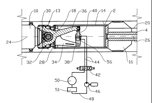
Figure 2 shows, on a larger scale and partially in section,

the steering axle and actuator of the drilling
unit, the control valve and hydraulic circuit being
shown schematically; and

Figure 3 shows the same as figure 2, but here the actuator
piston has been displaced.

In the drawings the reference numeral 1 indicates a drilling
unit of a rock-drilling machine not shown in its entirety.

The drilling unit 1 is located in a borehole 2 in the rock 3
and is connected by means of a feeding rod 4 to a feeding
machine, not shown, located outside the borehole 2.

The drilling unit 1 includes a pilot drill bit 6 and an
underreamer drill bit 8 which is located somewhat behind the
pilot drill bit 6. The drill bits 6 and 8 are driven by an

electric motor 10 via a gearbox 12.

The motor 10 is connected, together with the gearbox 12 and
drill bits 6 and 8, to a steering joint 13 connected in turn
to an intermediate housing 14. At its opposite end portion

the intermediate housing 14 is fixedly connected to a support
16 and to the inner end portion of the feeding rod 4. The
drilling unit 1 bears on the borehole 2 by the drill bits 6,
8 and by the support 16. The pivot axis of the steering joint
13 forms a steering axis 18.


CA 02658201 2009-01-15
WO 2008/013458 PCT/N02007/000268
A power and control cable 20 extends along the borehole 2
from a control system 22 located outside the borehole 2 in to
the drilling unit 1.

In figure 1 the centre axis 24 of the drill bits 6 and 8 has
5 been given an angle a relative to the centre axis 26 of the
feeding rod 4.

The steering joint 13 is connected to the intermediate
housing 14 by means of an axle mount 28, see figure 2,
supporting a steering axle 30. The centre axis of the

steering axle 30 coincides with the steering axis 18.

A bearing housing 32, which is bearingly rotatable about the
steering axle 30, is connected to the motor 10. The axle
mount 28, steering axle 30 and bearing housing 32 form the
steering joint 13. The torque of the motor 10 is transmitted

via the steering joint 13, intermediate housing 14 and
feeding rod 4 to the feeding machine not shown.

A counter arm 34, which is connected to the axle mount 28,
projects somewhat into the intermediate housing 14.
Correspondingly, a steering arm 36 connected to the bearing
housing 32 also projects somewhat into the intermediate
housing 14. An actuator 38, here in the form of a hydraulic
cylinder, is connected between the free end portions of the
counter arm 34 and the steering arm 36.

Movement of the piston rod 40 of the actuator 38 causes the
steering arm 36 together with the bearing housing 32, motor
10, gearbox 12 and drill bits 6 and 8 to be pivoted about the
steering axis 18, so that the angle a between the centre axis
24 of the drill bits 6, 8 and the centre axis 26 of the
feeding rod 4 changes, see figure 3.

The actuator 38 is connected to a control valve 42 by means


CA 02658201 2009-01-15
WO 2008/013458 PCT/N02007/000268
6
of pipe connections 44. The coupling is shown schematically
in figure 2. The control valve 42 is supplied with
pressurized fluid from a circulation pump 46 via circulation
pipes 48. The circulation pump 46 normally circulates fluid
to the support of the drill bits 6, 8, indicated here
schematically by the reference numeral 50, via a tank 51.
The control valve 42 is controlled and the circulation pump
46 is supplied with energy by means of wires, not shown, via
the power and control cable 20.

The control system 22 includes a control cabinet 52 with
necessary components and a control console 54. From the
control console 54 the position, power consumption and
operating temperature, for example, of the rock-drilling
machine may be monitored in a manner known per se.

When it is indicated that the direction of drilling of the
drilling unit 1 should be adjusted, the feeding rod 4 is
rotated, if necessary, about its centre axis 26 until the
steering axis 18 takes the desired direction. The control
valve 42 is activated so that the piston rod 40 is moved in

the actuator 38 until the angle a takes the desired value,
which is fed back from a transmitter 56 at the actuator 38.
The circulation pump 46 and control valve 42 is disposed in
the intermediate housing 14. The intermediate housing 14 may
form a fluid reservoir for pressurized fluid.

Flushing water for cleaning the drill bits 6, 8 is supplied
via the feeding rod 4, flowing via conduit elements, not
shown, through the intermediate housing 14, steering joint
13, motor 10, gearbox 12 up to the drill bits 6, 8.

Dessin représentatif
Une figure unique qui représente un dessin illustrant l'invention.
États administratifs

Pour une meilleure compréhension de l'état de la demande ou brevet qui figure sur cette page, la rubrique Mise en garde , et les descriptions de Brevet , États administratifs , Taxes périodiques et Historique des paiements devraient être consultées.

États administratifs

Titre Date
Date de délivrance prévu 2012-06-05
(86) Date de dépôt PCT 2007-07-12
(87) Date de publication PCT 2008-01-31
(85) Entrée nationale 2009-01-15
Requête d'examen 2009-11-04
(45) Délivré 2012-06-05

Historique d'abandonnement

Il n'y a pas d'historique d'abandonnement

Taxes périodiques

Dernier paiement au montant de 473,65 $ a été reçu le 2023-06-21


 Montants des taxes pour le maintien en état à venir

Description Date Montant
Prochain paiement si taxe applicable aux petites entités 2024-07-12 253,00 $
Prochain paiement si taxe générale 2024-07-12 624,00 $

Avis : Si le paiement en totalité n'a pas été reçu au plus tard à la date indiquée, une taxe supplémentaire peut être imposée, soit une des taxes suivantes :

  • taxe de rétablissement ;
  • taxe pour paiement en souffrance ; ou
  • taxe additionnelle pour le renversement d'une péremption réputée.

Les taxes sur les brevets sont ajustées au 1er janvier de chaque année. Les montants ci-dessus sont les montants actuels s'ils sont reçus au plus tard le 31 décembre de l'année en cours.
Veuillez vous référer à la page web des taxes sur les brevets de l'OPIC pour voir tous les montants actuels des taxes.

Historique des paiements

Type de taxes Anniversaire Échéance Montant payé Date payée
Le dépôt d'une demande de brevet 400,00 $ 2009-01-15
Taxe de maintien en état - Demande - nouvelle loi 2 2009-07-13 100,00 $ 2009-01-15
Requête d'examen 800,00 $ 2009-11-04
Taxe de maintien en état - Demande - nouvelle loi 3 2010-07-12 100,00 $ 2010-06-01
Taxe de maintien en état - Demande - nouvelle loi 4 2011-07-12 100,00 $ 2011-06-07
Enregistrement de documents 100,00 $ 2011-08-10
Taxe finale 300,00 $ 2012-03-01
Taxe de maintien en état - brevet - nouvelle loi 5 2012-07-12 200,00 $ 2012-07-05
Taxe de maintien en état - brevet - nouvelle loi 6 2013-07-12 200,00 $ 2013-06-12
Taxe de maintien en état - brevet - nouvelle loi 7 2014-07-14 200,00 $ 2014-06-05
Taxe de maintien en état - brevet - nouvelle loi 8 2015-07-13 200,00 $ 2015-06-30
Taxe de maintien en état - brevet - nouvelle loi 9 2016-07-12 200,00 $ 2016-06-08
Taxe de maintien en état - brevet - nouvelle loi 10 2017-07-12 250,00 $ 2017-06-26
Taxe de maintien en état - brevet - nouvelle loi 11 2018-07-12 450,00 $ 2018-08-09
Taxe de maintien en état - brevet - nouvelle loi 12 2019-07-12 250,00 $ 2018-08-09
Taxe de maintien en état - brevet - nouvelle loi 13 2020-07-13 250,00 $ 2020-06-17
Taxe de maintien en état - brevet - nouvelle loi 14 2021-07-12 255,00 $ 2021-06-10
Taxe de maintien en état - brevet - nouvelle loi 15 2022-07-12 458,08 $ 2022-06-02
Taxe de maintien en état - brevet - nouvelle loi 16 2023-07-12 473,65 $ 2023-06-21
Titulaires au dossier

Les titulaires actuels et antérieures au dossier sont affichés en ordre alphabétique.

Titulaires actuels au dossier
NORWEGIAN HARD ROCK DRILLING AS
Titulaires antérieures au dossier
HAUGHOM, SIGURD KJELL
KNUTSEN, KJELL
SIRA-KVINA KRAFTSELSKAP DA
Les propriétaires antérieurs qui ne figurent pas dans la liste des « Propriétaires au dossier » apparaîtront dans d'autres documents au dossier.
Documents

Pour visionner les fichiers sélectionnés, entrer le code reCAPTCHA :


Pour visualiser une image, cliquer sur un lien dans la colonne description du document. Pour télécharger l'image (les images), cliquer l'une ou plusieurs cases à cocher dans la première colonne et ensuite cliquer sur le bouton "Télécharger sélection en format PDF (archive Zip)" ou le bouton "Télécharger sélection (en un fichier PDF fusionné)".

Liste des documents de brevet publiés et non publiés sur la BDBC .

Si vous avez des difficultés à accéder au contenu, veuillez communiquer avec le Centre de services à la clientèle au 1-866-997-1936, ou envoyer un courriel au Centre de service à la clientèle de l'OPIC.


Description du
Document 
Date
(yyyy-mm-dd) 
Nombre de pages   Taille de l'image (Ko) 
Dessins 2009-01-16 3 63
Abrégé 2009-01-15 1 65
Revendications 2009-01-15 3 81
Dessins 2009-01-15 3 61
Description 2009-01-15 6 227
Dessins représentatifs 2009-01-15 1 13
Page couverture 2009-05-29 2 50
Revendications 2011-09-22 2 43
Dessins représentatifs 2012-05-10 1 13
Page couverture 2012-05-11 1 46
Poursuite-Amendment 2011-09-22 4 77
Poursuite-Amendment 2009-11-04 2 51
Correspondance 2009-04-08 1 37
Paiement de taxe périodique 2017-06-26 1 33
PCT 2009-01-15 3 90
Cession 2009-01-15 4 85
Poursuite-Amendment 2009-01-15 2 67
Correspondance 2009-04-30 1 25
Poursuite-Amendment 2009-11-04 1 35
Cession 2011-08-10 4 115
Poursuite-Amendment 2011-04-04 3 87
Correspondance 2012-03-01 2 49
Taxes 2015-06-30 1 33