Note : Les descriptions sont présentées dans la langue officielle dans laquelle elles ont été soumises.
CA 02660046 2009-02-04
WO 2008/027915 PCT/US2007/077028
1
SYSTEM FRAME NUMBER (SFN) EVALUATOR
BACKGROUND
Field
[0001] The present invention relates generally to synchronization in
communication
systems, and more specifically to system frame number error detection.
Background
[0002] Many wireless communication systems employ communication protocols that
arrange control information and data into frames where an access terminal
(user
communication device) references the timing of reception and transmission
tasks based
on a system frame number (SFN). An access terminal, for example, may access
information transmitted from a communication network within a particular frame
referenced to the current (SFN). Accordingly, the access terminal must
maintain frame
synchronization with a communication network by tracking and updating the SFN
in
order to properly receive information. For example, in an asynchronous
communication
system such as system operating in accordance with WCDMA standards, a base
station
pages the access terminal during Paging Occasions that are based on the SFN of
the cell
at the particular time. The access terminal deciphers a frame of a Page
Indicator
Channel (PICH) where the frame is based on the current SFN. If the SFN of the
access
terminal is not synchronized to the SFN of the cell, the access terminal will
not receive a
page and will not be able to receive calls. One potential method for
maintaining SFN
synchronization between the access terminal and the cell includes requiring
the access
terminal to constantly monitor a Broadcast Channel (BCH) where each BCH block
includes an encoded SFN. Unfortunately, this technique is not practical due to
the
resulting power consumption and negative impact on battery life of the access
terminal.
Some conventional systems allow the access terminal to rely on the SFN that is
maintained at the access terminal without monitoring the BCH. This technique
is
limited since if the SFN is incorrect at the access terminal, the access
terminal will not
be able to receive calls or otherwise maintain frame synchronization with the
communication network.
[0003] Accordingly, there is a need for system frame number (SFN) evaluation.
CA 02660046 2009-02-04
WO 2008/027915 PCT/US2007/077028
2
SUMMARY
[0004] An access terminal reacquires a system frame number (SFN) when a
difference between a continuous counter elapsed time and a calculated elapsed
time
exceeds a threshold. The continuous counter elapsed time is generated by a
continuous
counter remaining active during a sleep state and the calculated elapsed time
is based on
a SFN derived from a counter value generated by a discontinuous counter that
is
deactivated during the sleep state. In one aspect, the continuous counter may
be clocked
by a continuous clock during a sleep mode of the access terminal and the
discontinuous
counter may be clocked by a faster clock that is deactivated during the sleep
mode.
During reactivation after the sleep mode, the discontinuous counter is set, at
the counter
set time, to a reset counter value corresponding to an SFN indicated by the
continuous
counter.
BRIEF DESCRIPTION OF THE DRAWINGS
[0005] FIG. 1 is a block diagram of communication system 100 in accordance
with the
exemplary embodiment of the invention.
[0006] FIG. 2 is a[INSERT FIGURE DESCRIPTION];
[0007] FIG. 3 is a[INSERT FIGURE DESCRIPTION];
[0008] FIG. 4 is a[INSERT FIGURE DESCRIPTION]; and
[0009] FIG. 5 is a[INSERT FIGURE DESCRIPTION].
DETAILED DESCRIPTION
[0010] The word "exemplary" is used herein to mean "serving as an example,
instance,
or illustration." Any embodiment described herein as "exemplary" is not
necessarily to
be construed as preferred or advantageous over other embodiments.
[0011] FIG. 1 is a block diagram of communication system 100 in accordance
with the
exemplary embodiment of the invention. The communication system 100 includes
at
least one access terminal 102 communicating with at least one base station 104
through
a wireless communication link 106. In most implementations, however, several
base
stations 104 connected through a communication network provide wireless
service to
access terminals 102 within a plurality of geographical areas. For example,
base stations
104 may be connected through wired or wireless backhaul to base station
controllers
and a network controller.
CA 02660046 2009-02-04
WO 2008/027915 PCT/US2007/077028
3
[0012] The access terminal 102 is any wireless communication device that
communicates with one or more base stations through the wireless communication
link
106 and is also referred to as a remote terminal, modem, portable
communication device
and user equipment, among other terms. Examples of access terminals 102
include, but
are not limited to, cellular telephones, wireless personal digital assistants
(PDAs),
wireless modems, and wireless PCMCIA cards. The access terminal 102 may
include
hardware, software, and/or firmware not shown in FIG. 1 for facilitating and
performing
the functions of the access terminal 102. For example, the access terminal 102
may
include input and output devices such as keypads, displays, microphones and
speakers
in some circumstances. The various functions and operations of the blocks
described
with reference to the access terminal 102 may be implemented in any number of
devices, circuits, or elements. Two or more of the functional blocks may be
integrated in
a single device and the functions described as performed in any single device
may be
implemented over several devices in some circumstances. For example, some of
the
functions of a transceiver 108 may be performed by a controller 114 in some
circumstances.
[0013] In the exemplary embodiment, the access terminal 102 and base station
104
transmit and receive signals in accordance with WCDMA protocols and standards.
The
techniques discussed herein however, may be applied to any communication
system 100
that requires an access terminal to receive, transmit, or process information
based on a
system frame number (SFN). In accordance with WCDMA standards, the SFN
sequence
is a sequence of 12 bit numbered frames from 0 to 4095 that continually
repeats. Each
SFN cycle completes in 40.96 seconds since each frame has a length of lOms.
The
current SFN is transmitted by the base station on the Broadcast Channel (BCH)
through
the wireless communication link 106.
[0014] In accordance with the exemplary embodiment, the access terminal 102
includes
an SFN evaluator 116 that indicates a possible error in the SFN that is
maintained at the
access terminal 102 when certain conditions are met. The SFN evaluator 116 may
be
implemented in any combination of hardware, software and/or firmware. In the
exemplary embodiment, software code running on the controller 114 executes the
calculations, comparisons, and adjustments to perform the functions of the SFN
evaluator 116. The controller 114 includes any combination of software,
hardware
and/or firmware for executing the functions described herein as well as
facilitating the
overall functionality of the access terminal 102. In the exemplary embodiment,
the
CA 02660046 2009-02-04
WO 2008/027915 PCT/US2007/077028
4
controller 114 includes a processor such as a microprocessor and any necessary
hardware.
[0015] A transceiver 108 in the access terminal 102 includes a transmitter 110
and
receiver 112 for communicating with the base station 104 through the wireless
communication link 106. The receiver 112 is configured to receive the BCH to
allow a
controller 114 to decode the current SFN. The receiver 112 also receives
control
channels that are based on the SFN. Accordingly, the controller 114 extracts
the
appropriate system information from the various channels based on the SFN
estimate
that is maintained at the access terminal 102. For example, a paging indictor
channel
(PICH) is transmitted in accordance with a discontinuous reception (DRX)
scheme over
the cell of the base station 104 where the unique location of the paging
indicator is
based on the SFN.
[0016] DRX facilitates a sleep cycle for the access terminal 102 allowing the
access
terminal to periodically deactivate and reactivate circuits to conserve power.
The access
terminal powers up deactivated circuits and components prior to the arrival of
the PICH.
Accordingly, the access terminal 102 maintains an estimate of the SFN when in
the
sleep state in order to reactivate circuits and timely receive the paging
indicator in the
PICH.
[0017] In accordance with the exemplary embodiment, a continuous clock 118 and
discontinuous clock 120 are used for timing and SFN synchronization where the
continuous clock 118 is slower and consumes less power than the discontinuous
clock
120. The discontinuous clock 120 is a "fast" clock that has a frequency and
accuracy
greater than the continuous clock 118 and provides a reference for radio
frequency
functions as well as processor and logic tasks during non-sleep operation of
the access
terminal 102. The discontinuous clock 120 typically has a frequency equal to a
frequency 32 times the chip rate. Another example of a suitable frequency is 8
times the
chip rate. An example of a suitable discontinuous clock includes a crystal
clock
oscillator operating at 122.88 MHZ. The continuous clock 118 provides a
reference for
a continuous counter 122 that generates a continuous counter value indicative
of a first
SFN estimate. During the sleep state, the continuous counter 122 is clocked by
the
continuous clock 118 and provides the only information regarding the SFN. In
the
exemplary embodiment, the continuous counter 122 is a 32 bit counter that
counts from
0 to 4294967295 and the continuous clock 118 has a frequency of 32.768 kHz.
The
continuous counter 122 increments every slow clock period (1/32768) equal to
30 micro
CA 02660046 2009-02-04
WO 2008/027915 PCT/US2007/077028
seconds. Therefore, the continuous clock 122 starts at 0 and increments by 1
every 30
microseconds. The continuous clock 122 returns to 0 every 232132768 seconds
which is
equal to approximately 36 hours. In some cases where the counter is smaller
such as 16
bit counter, additional rollover counters or logic may be necessary to allow
the counter
to count to the appropriate value.
[0018] After reactivation of the discontinuous clock 120 and other circuits
deactivated
during the sleep state, the discontinuous counter 124 is set with a counter
set value 126
that corresponds to the first estimated SFN indicated by the continuous
counter 118. In
the exemplary embodiment, adequate time is allowed for the discontinuous clock
120 to
stabilize before the discontinuous counter 124 is set with the counter set
value 126.
Accordingly, the counter set time is at a time after the reactivation of the
discontinuous
clock 120 but before the arrival of the PICH.
[0019] The controller 114 calculates the counter set value 126 for the
discontinuous
counter 124 based on the continuous counter value and the anticipated time
that the
discontinuous counter 124 will be set (counter set time) such that if the
discontinuous
counter 124 is set properly, the discontinuous counter 124 and the continuous
counter
122 will both indicate the same estimated current SFN. If, however, an error
event
occurs, the discontinuous estimated current SFN indicated by the discontinuous
counter
value will be different from the continuous estimated current SFN indicated by
the first
counter 122. An error event may be due to any of numerous conditions or
reasons.
Examples of error event causes include software bugs, race conditions, clock
glitches,
long interrupts and long interrupt locked periods. Accordingly, an error event
is any
event or mismatch that negatively affects the reactivation of the
discontinuous clock
120, calculation of the counter set value 126, the setting of the
discontinuous counter
124, or otherwise causes a mismatch between the SFNs corresponding to the two
counter values.
[0020] In accordance with the exemplary embodiment, the controller performs a
SFN
evaluation procedure just prior to entering every sleep cycle. The SFN
evaluation
procedure may be performed anytime between the reactivation of the circuits
after sleep
and the following deactivation of circuits for the next sleep cycle, however.
Further, in
some circumstances, the SFN evaluation procedure is not performed at every
cycle. For
example, if the current SFN is obtained from the network during the active
cycle
immediately prior to a sleep cycle, the SFN error detection procedure is not
performed.
CA 02660046 2009-02-04
WO 2008/027915 PCT/US2007/077028
6
[0021] The exemplary SFN evaluation procedure includes comparing the
continuous
counter elapsed time and a calculated elapsed time where the calculated
elapsed time is
based on the SFN derived from the discontinuous counter. If the time
difference
between the continuous counter elapsed time and the calculated time is greater
than a
threshold, the controller initiates an SFN reacquisition procedure. In the
exemplary
embodiment, the threshold is 7.0 milliseconds. Other thresholds may be used in
some
circumstances. Selection of the threshold is based on the particular
implementation and
takes balances the possibility of falsely determining an error has occurred
with the
possibility of missing a SFN error. With long DRX cycles such as where Paging
Occasions separated by 5.12 second, elapsed time differences may eventually
drift to 4
or 5 ms. Accordingly, a threshold greater than 5 ms but less than 10 ms is
appropriate in
some circumstances. A threshold between 6 ms and 9 ms provides less chance for
false
positives and missed errors.
[0022] The SFN reacquisition procedure may be invoked in circumstances other
than
the exceeding of the threshold. For example, the SFN reacquisition procedure
may be
performed periodically regardless of the difference between the calculated
elapsed time
and the continuous counter elapsed time. In the exemplary embodiment, a SFN
reacquisition timer invokes the SFN reacquisition procedure every 2 hours.
[0023] FIG. 2 is a block diagram of an exemplary implementation of the system
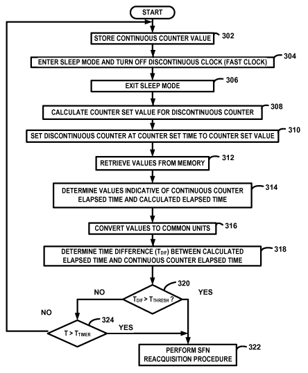
frame
number (SFN) evaluator 116. As discussed above, code running on a processor
performs the functions of the SFN evaluator 116 in the exemplary embodiment.
The
SFN evaluator 116, however, may be implemented with any combination of
hardware,
software, and/or firmware. Further, the various functions and operations of
the blocks
described with reference to the SFN evaluator 116 may be implemented in any
number
of devices, circuits, or elements. Two or more of the functional blocks may be
integrated in a single device and the functions described as performed in any
single
block may be implemented over several devices in some circumstances. Depending
on
the particular implementation, the order of execution of the various tasks may
be
different in some circumstances.
[0024] The SFN evaluator 116 evaluates the difference between the elapsed
times
indicated by the continuous counter and the calculated elapsed time based on
the SFN
derived from the discontinuous counter to determine if the SFN timing
maintained at the
access terminal 102 may be inaccurate. If the elapsed time indicated by
continuous
counter value indicates an elapsed time that differs from the calculated
elapsed time
CA 02660046 2009-02-04
WO 2008/027915 PCT/US2007/077028
7
indicated by the SFN and the discontinuous counter by more than a threshold,
the SFN
evaluator 116 invokes the SFN reacquisition procedure.
[0025] In the exemplary embodiment, the SFN evaluator 116 includes, or has
access to,
a memory 202. The memory 202 is any type of memory device suitable for storing
the
counter values and the SFN. Before entering a sleep state, the current SFN and
continuous counter value are stored in memory 202. In some circumstances,
values
other than the SFN may be stored. For example, the discontinuous counter value
may be
stored. During the sleep state, circuits, except for the continuous clock 118
and
continuous counter 122, are deactivated. The discontinuous clock 120 and
discontinuous
counter 124 are deactivated during the sleep state. When the access terminal
102 exits
the sleep state, the deactivated circuits are activated. After the
discontinuous clock 120
has stabilized, the discontinuous counter 124 is set with a counter value
corresponding
to the SFN indicated by the continuous counter value (set value 126) as
discussed
above.
[0026] The SFN evaluator 116 evaluates the SFN and the continuous counter
value
before the next sleep cycle in order to determine if the discontinuous counter
124 has
been incorrectly set or if there is otherwise a discrepancy between the SFN
and the
continuous clock 122. The SFN evaluator 116 can be invoked at any time during
the
active (non-sleep) cycle before the next sleep state.
[0027] The SFN evaluator 116 retrieves the previous cycle continuous counter
value
208 from memory 202. An adder 212 subtracts the previous cycle continuous
counter
value 208 from the current cycle continuous counter value 204 to generate a
value
indicative of the elapsed time of the continuous counter 122. In the exemplary
embodiment, is in units of clock cycles of the continuous clock 118. A
converter
converts the value generated by the adder 212 into a continuous counter
elapsed time
220 that has units of time such as for example, milliseconds.
[0028] The previous cycle SFN 210 is retrieved from memory and subtracted from
the
current SFN 206 by an adder 214 to generate a value indicative of the
calculated elapsed
time based on the SFN. As described herein, the SFN values include the frame
number
as well as the sub frame number. Accordingly, calculations involving the SFN
values
account for the frame number and the sub frame number. The previous cycle SFN
may
be stored in other units in some implementations. For example, the previous
cycle SFN
210 and the current SFN 206 may be in units of time in some cases. The
converter 218
converts the value generated by the adder 214 to a calculated elapsed time 222
that has
CA 02660046 2009-02-04
WO 2008/027915 PCT/US2007/077028
8
units of time consistent with the continuous counter elapsed time 220 in order
that the
elapsed times 220, 222 may be appropriately compared in the elapsed time
comparer
224.
[0029] In the exemplary embodiment, the elapsed time comparer 224 determines a
difference between the calculated elapsed time and the continuous counter
elapsed time
220. The absolute value of the difference is compared to a threshold by the
threshold
evaluator 226. If the difference is greater than the threshold, the SFN
evaluator 116
determines that the SFN is not reliable and invokes a SFN reacquisition
procedure by
indicating that reacquisition is required with a reacquisition required
indicator 230.
Otherwise, a no reacquisition required indicator 228 is generated. As
explained above, a
reacquisition procedure may by invoked by the controller in response to other
conditions in addition to the generation of the reacquisition required
indicator 230. The
SFN reacquisition procedure may be periodically performed or the detection of
other
errors may invoke the procedure.
[0030] FIG. 3 is a flow chart of a method of performing the SFN evaluation
procedure
in accordance with the exemplary embodiment of the invention. Although the
method is
performed by executing code on the processor in the exemplary embodiment, the
methods may be performed by any combination of software, hardware and/or
firmware.
Further, the steps discussed with reference to FIG. 3 may be performed in any
order and
two or more steps may be performed simultaneously in some circumstances.
[0031] At step 302, the value of the continuous counter 122 is stored in
memory 202. A
"snapshot" of the counter value is taken prior to entering the sleep mode at
step 304.
[0032] At step 304, the discontinuous clock is turned off and the access
terminal enters
the sleep state. In the exemplary embodiment, the discontinuous counter and
other
circuits are deactivated in addition to the discontinuous clock in the sleep
state. The
continuous counter 122 and the continuous clock 118 remain active in the sleep
state.
[0033] At step 306, the access terminal 202 exits the sleep state. The
discontinuous
clock, discontinuous counter and other circuits are activated (turned on). The
discontinuous clock is provided adequate time to stabilize before the
procedure
continues at step 310.
[0034] At step 310, the discontinuous counter 124 is set to the counter set
value 126.
The counter set value 126 is calculated based on the current value of the
continuous
counter 122 and the counter set time such that the discontinuous counter 124
should
CA 02660046 2009-02-04
WO 2008/027915 PCT/US2007/077028
9
reflect the same SFN as the continuous counter 122 after the discontinuous
counter 124
is set.
[0035] At step 312, the previous cycle continuous counter value 208 and the
previous
cycle SFN 210 are retrieved from memory 202. In some circumstances, the
current SFN
206 and the current cycle continuous counter value 204 may also be retrieved
from
memory 202. For example, the current SFN 206 and the current cycle continuous
counter value 204 may be captured and temporarily stored in memory 202 before
or
during the SFN evaluation procedure.
[0036] At step 314, the values indicative of the continuous counter elapsed
time and the
calculated elapsed time based on the SFN are determined. The difference
between the
previous cycle values and the current cycle values is determined. As explained
above,
although these values correspond to t an elapsed time, the values may have
units that are
not time. For example, the units may be clock cycles or SFN and SFN sub
frames.
[0037] At step 316, the values are converted to elapsed time values.
Accordingly, the
continuous counter elapsed time 220 and the calculated elapsed time 222 are
generated.
An example of a suitable unit of measure includes milliseconds. In some
circumstances,
the conversions may occur before calculating the differences between the
current and
previous values.
[0038] At step 318, the time difference (TDiFF) between the calculated elapsed
time
based on the SFN and the continuous counter elapsed time is determined. The
absolute
value of the difference is used in step 320 since the calculated elapsed time
may be
greater than or less than the continuous counter elapsed time.
[0039] At step 320, the time difference (TDiFF) is compared to a threshold. If
the time
difference is greater than the threshold, the SFN reacquisition procedure is
performed at
step 322. Otherwise, the method continues at step 324. The threshold in the
exemplary
embodiment is 7 milliseconds.
[0040] At step 324, it is determined whether the elapsed time since the SFN
was
received from the network exceeds a timer threshold. If the time since the
last the last
SFN reception is greater than the timer threshold, the procedure proceeds to
step 322.
Otherwise, the method returns to step 302 continue with the next DRX cycle.
[0041] At step 322, the SFN reacquisition procedure is performed. As discussed
above,
the BCH is received decoded and processed to acquire the encoded SFN. The
newly
acquired SFN is used to set the discontinuous counter 124.
CA 02660046 2009-02-04
WO 2008/027915 PCT/US2007/077028
[0042] The methods and apparatus of this invention may take the form, at least
partially, of program logic or program code (i.e., instructions) embodied in
tangible
media, such as floppy diskettes, CD-ROMs, hard drives, random access or read
only-
memory, or any other machine-readable storage medium. When the program code is
loaded into and executed by a machine, such as a computer, the machine becomes
an
apparatus for practicing the invention. The methods and apparatus of the
present
invention may also be embodied in the form of program code that is transmitted
over
some transmission medium, such as over electrical wiring or cabling, through
fiber
optics, through a wireless interface or via any other form of transmission.
When the
program code is received and loaded into and executed by a machine, such as a
processor, the machine becomes an apparatus for practicing the invention. When
implemented on a general-purpose processor, the program code combines with the
processor to provide a unique apparatus that operates analogously to specific
logic
circuits. Accordingly, a program product including instructions contained on a
computer-readable medium results in the performance of one or more steps
discussed
with reference FIG. 3 when the program product is executed by a controller or
processor.
[0043] Those of skill in the art would understand that information and signals
may be
represented using any of a variety of different technologies and techniques.
For
example, data, instructions, commands, information, signals, bits, symbols,
and chips
that may be referenced throughout the above description may be represented by
voltages, currents, electromagnetic waves, magnetic fields or particles,
optical fields or
particles, or any combination thereof.
[0044] Those of skill would further appreciate that the various illustrative
logical
blocks, modules, circuits, and algorithm steps described in connection with
the
embodiments disclosed herein may be implemented as electronic hardware,
computer
software, or combinations of both. To clearly illustrate this
interchangeability of
hardware and software, various illustrative components, blocks, modules,
circuits, and
steps have been described above generally in terms of their functionality.
Whether such
functionality is implemented as hardware or software depends upon the
particular
application and design constraints imposed on the overall system. Skilled
artisans may
implement the described functionality in varying ways for each particular
application,
but such implementation decisions should not be interpreted as causing a
departure from
the scope of the present invention.
CA 02660046 2009-02-04
WO 2008/027915 PCT/US2007/077028
11
[0045] The various illustrative logical blocks, modules, and circuits
described in
connection with the embodiments disclosed herein may be implemented or
performed
with a general purpose processor, a digital signal processor (DSP), an
application
specific integrated circuit (ASIC), a field programmable gate array (FPGA) or
other
programmable logic device, discrete gate or transistor logic, discrete
hardware
components, or any combination thereof designed to perform the functions
described
herein. A general purpose processor may be a microprocessor, but in the
alternative, the
processor may be any conventional processor, controller, microcontroller, or
state
machine. A processor may also be implemented as a combination of computing
devices, e.g., a combination of a DSP and a microprocessor, a plurality of
microprocessors, one or more microprocessors in conjunction with a DSP core,
or any
other such configuration.
[0046] The steps of a method or algorithm described in connection with the
embodiments disclosed herein may be embodied directly in hardware, in a
software
module executed by a processor, or in a combination of the two. A software
module
may reside in RAM memory, flash memory, ROM memory, EPROM memory,
EEPROM memory, registers, hard disk, a removable disk, a CD-ROM, or any other
form of storage medium known in the art. An exemplary storage medium is
coupled to
the processor such the processor can read information from, and write
information to,
the storage medium. In the alternative, the storage medium may be integral to
the
processor. The processor and the storage medium may reside in an ASIC. The
ASIC
may reside in a user terminal. In the alternative, the processor and the
storage medium
may reside as discrete components in a user terminal.
[0047] The previous description of the disclosed embodiments is provided to
enable any
person skilled in the art to make or use the present invention. Various
modifications to
these embodiments will be readily apparent to those skilled in the art, and
the generic
principles defined herein may be applied to other embodiments without
departing from
the spirit or scope of the invention. Thus, the present invention is not
intended to be
limited to the embodiments shown herein but is to be accorded the widest scope
consistent with the principles and novel features disclosed herein.