Sélection de la langue

Search

Sommaire du brevet 2671880 

Énoncé de désistement de responsabilité concernant l'information provenant de tiers

Une partie des informations de ce site Web a été fournie par des sources externes. Le gouvernement du Canada n'assume aucune responsabilité concernant la précision, l'actualité ou la fiabilité des informations fournies par les sources externes. Les utilisateurs qui désirent employer cette information devraient consulter directement la source des informations. Le contenu fourni par les sources externes n'est pas assujetti aux exigences sur les langues officielles, la protection des renseignements personnels et l'accessibilité.

Disponibilité de l'Abrégé et des Revendications

L'apparition de différences dans le texte et l'image des Revendications et de l'Abrégé dépend du moment auquel le document est publié. Les textes des Revendications et de l'Abrégé sont affichés :

  • lorsque la demande peut être examinée par le public;
  • lorsque le brevet est émis (délivrance).
(12) Brevet: (11) CA 2671880
(54) Titre français: VOLANT POUR COMMANDE DE LAME TEMPORISEE
(54) Titre anglais: FLYWHEEL FOR TIMED KNIFE DRIVE
Statut: Réputé périmé
Données bibliographiques
(51) Classification internationale des brevets (CIB):
  • A01D 41/14 (2006.01)
  • A01D 57/20 (2006.01)
(72) Inventeurs :
  • TIPPERY, STEVE (Etats-Unis d'Amérique)
  • KASTER, CRAIG (Etats-Unis d'Amérique)
(73) Titulaires :
  • CLAAS SELBSTFAHRENDE ERNTEMASCHINEN GMBH (Allemagne)
(71) Demandeurs :
  • CLAAS SELBSTFAHRENDE ERNTEMASCHINEN GMBH (Allemagne)
(74) Agent: KIRBY EADES GALE BAKER
(74) Co-agent:
(45) Délivré: 2012-04-24
(22) Date de dépôt: 2009-07-15
(41) Mise à la disponibilité du public: 2010-04-20
Requête d'examen: 2009-08-21
Licence disponible: S.O.
(25) Langue des documents déposés: Anglais

Traité de coopération en matière de brevets (PCT): Non

(30) Données de priorité de la demande:
Numéro de la demande Pays / territoire Date
12/254,565 Etats-Unis d'Amérique 2008-10-20

Abrégés

Abrégé français

Un dispositif d'entraînement de barre de coupe pour table de coupe de tuloteuse est muni d'une barre de coupe placée à un bord avant de la table de coupe pour couper une récolte. Une boîte d'engrenage de barre de coupe à accouplement opératif avec la barre de coupe est installée sur une partie avant de la table de coupe, avec une transmission montée sur la table de coupe pour entraîner la boîte d'engrenage et la barre de coupe. Un volant extérieur occupe la transmission, loin de la boîte d'engrenage et s'accouple avec la transmission pour réduire les vibrations de la barre de coupe et de la boîte d'engrenage, à partir d'un emplacement extérieur éloigné.


Abrégé anglais

A cutter bar drive system for a draper header has a cutter bar disposed at a leading edge of the header to cut crop. A cutter bar gear box in operative engagement with the cutter bar is mounted on a forward portion of the header with a drive train mounted on the header to drive the gear box and cutter bar. An external flywheel is mounted along the drive train remote from the gear box and is engaged with the drive train to reduce vibration in the cutter bar and gear box from a remote, external position.

Revendications

Note : Les revendications sont présentées dans la langue officielle dans laquelle elles ont été soumises.


CLAIMS
1. A draper header for a harvester or combine having a cutter bar drive system

comprising:
a header frame having a front, a rear and a side, said rear of said header
frame
having a top and a bottom;
a cutter bar mounted on said front;
a rear drive shaft mounted on said rear of said header frame;
a T gear box mounted on said top of said rear of said header frame and said T
gear box being operatively engaged with said rear drive shaft;
a side drive shaft, said side drive shaft being mounted on said side of said
header frame and said side drive shaft being operatively engaged with a first
drive hub
of said T gear box;
a cutter bar gear box mounted on a front portion of said side of said header
frame, said cutter bar gear box being driven by said side drive shaft and said
cutter bar
gear box driving said cutter bar; and
a flywheel mounted on an opposing drive hub of said T gear box such that said
flywheel is separated from said cutter bar gear box by a length of said side
drive shaft
and by said T gear box and such that said flywheel is inertially engaged with
said
cutter bar gear box.


2. The draper header of claim 1, further comprising:
said header frame having a second side bilaterally opposing said side, said
second, opposing side having generally mounted on it;
a second cutter bar mounted on said front of said header frame;
a second rear drive shaft mounted on said rear of said header frame;
a second T gear box mounted on said top of said rear and operatively engaged
with said second rear drive shaft;
a second side drive shaft operatively engaged with a first drive hub of said
second T gear box, said second side drive shaft being mounted on said second
side;

6


a second cutter bar gear box mounted on a front portion of said second side,
said second cutter bar gear box being driven by said second side drive shaft
and said
second cutter bar gear box driving said second cutter bar; and
a second flywheel mounted on an opposing drive hub of said second T gear
box such that said second flywheel is separated from said second cutter bar
gear box
by a length of said second drive shaft and said second T gear box and such
that said
second flywheel is inertially engaged with said cutter bar gear box.


3. The draper header of claim 1, wherein a diameter of said flywheel exceeds a

diameter of said cutter bar gear box.


4. The draper header of claim 1, wherein said second T gear box is mounted to
turn an opposite direction than said first T gear box.


5. The draper header of claim 1, wherein said flywheel has a mass less than
about 33 kg.


6. The draper header of claim 1, wherein cyclical torque from said cutter bar
or
said gear box is substantially eliminated from said rear drive shaft.


7. The draper header of claim 1, further comprising a torsion dampener in said

drive system.


8. The draper header of claim 7, wherein said torsion dampener is mounted at a

rearward portion of said side drive shaft.


7

Description

Note : Les descriptions sont présentées dans la langue officielle dans laquelle elles ont été soumises.


CA 02671880 2009-07-15

Attorney Docket No: 459156-138
FLYWHEEL FOR TIMED KNIFE DRIVE

CROSS-REFERENCE TO RELATED APPLICATIONS
[0001] None.

STATEMENT REGARDING FEDERALLY SPONSORED RESEARCH
[0002] Not Applicable.

APPENDIX
[0003] Not Applicable.

BACKGROUND OF THE INVENTION
FIELD OF THE INVENTION

[0004] The present invention is in the field of agricultural combines and
harvesters,
particularly in drive systems for cutter bars.

RELATED ART

[0005] Combines and harvesters cut crop with a knife or cutter bar located on
the
leading edge of the combine header. Cutter bars oscillate at a rate of
hundreds of strokes per
minute. The cutter bars and gear boxes driving them therefore produce
vibration. Vibration
decreases product durability and increases operator fatigue.

[0006] It is known to use dual timed knife drives wherein each of the left and
right
hand side of the header has a separate cutter bar. The left and right hand
cutter bars are geared in
order that their oscillations mirror one another, and thereby mechanically
offset the vibrations
caused by one another. Although vibrations are reduced in this fashion, they
are not eliminated,
and the gear boxes themselves also generate vibrations. Gear box gear teeth
reciprocate, and
1
SLC-3104531-11

Copy provided by USPTO from the IFW Image Database on 05/28/2009


CA 02671880 2009-07-15

Attorney Docket No: 459156-13 8
drive line torque can reciprocate in both the positive and negative
directions, both of which are
detrimental to product durability.

SUMMARY OF THE INVENTION

[0007] The present invention is a drive system for a cutter bar gear box
incorporating
a flywheel. The flywheel is external to the gear box and remote from it. In
one embodiment of
the present invention, the flywheel is located at the rear of a draper header.

[0008] Further areas of applicability of the present invention will become
apparent
from the detailed description provided hereinafter. It should be understood
that the detailed
description and specific examples, while indicating the preferred embodiment
of the invention,
are intended for purposes of illustration only and are not intended to limit
the scope of the
invention.

BRIEF DESCRIPTION OF THE DRAWINGS

[0009] The present invention will become more fully understood from the
detailed
description and the accompanying drawings, wherein:

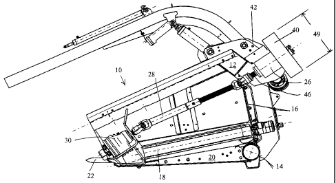
[00010] Figure 1 is a side view of the flywheel and drive system of the
present
invention.

[00011] Figure 2 is a rear perspective view of the flywheel and drive system.
[00012] Figure 3 is a cutaway side view of the flywheel and drive system.
[00013] Figure 4 is a side view of an alternative embodiment.

2
SLC-3104531-11

Copy provided by USPTO from the IFW Image Database on 05/28/2009


CA 02671880 2009-07-15

Attorney Docket No: 459156-138
DETAILED DESCRIPTION OF THE PREFERRED EMBODIMENTS

[00014] The following description of the preferred embodiment(s) is merely
exemplary in nature and is in no way intended to limit the invention, its
application, or uses.
[00015] Referring now to the drawings wherein like numbers indicate like
elements,

draper header 10 includes an upper rear frame member 12 and a lower rear frame
member 14 and
a rear wall 16. A draper 18 is mounted on the bottom 20 of the header and
disposed thereon to
be driven for the movement of crop towards the center of the header, there to
be guided into a
feeder house. A cutter bar 22 is mounted on the front of the bottom of the
header. The cutter bar
is driven by a mechanical drive. The mechanical drive includes a rear shaft
24, a T gear box 26,
a side drive shaft 28 and the fmal gear box 30 for the cutter bar. In the
depicted embodiment, the
final gear box 30 is an epicyclic planetary gear box. The gear box 30 is
operatively engaged
with cutter bar 22 so as to drive its oscillating strokes to cut crop.

[00016] At the rear of the header is a mounting bracket 42 on which the T gear
box is
fixed. From the T gear box in a forward direction proceeds the side drive
shaft 28. A universal
joint 44 joins side drive shaft 28 to side drive shaft hub 46. (Another
universal joint joins side
drive shaft 28 to gear box 30.) In an opposite direction and substantially in
line with the side
drive shaft hub 46 is the flywheel drive shaft hub 48. Thus the positioning of
the flywheel
allows it to be substantially in line with the gear box 30 in order to
suppress vibration and
reciprocation of the gear box gear teeth.

3
SLC-3104531-11

Copy provided by USPTO from the IFW Image Database on 05/28/2009


CA 02671880 2009-07-15

Attorney Docket No: 459156-138
[00017] The flywheel 40 is externally mounted. The flywheel 40 suppresses
vibration
through the effect of its inertia. Inertia is the product of mass and angular
velocity. A greater
diameter will therefore increase the useful inertia of a flywheel without a
disadvantageous
increase in mass. By mounting the flywheel 40 in an external position, remote
from the gear box
30, a greater diameter 49 may be used, thus advantageously reducing the
overall mass of the
header on which it is mounted while increasing vibration suppressing inertia.
Moreover,
mounting the flywheel in a remote location reduces the package size of the
gear box unit 30,
saving space at the front of the header, which allows narrower crop dividers
to be
advantageously used.

[00018] The drive system of the present invention may only drive a single side
knife
drive, or two knife drives. The two knife drives may be timed to offset one
anothers' vibrations
by oscillating reciprocally. In a two knife header, a second side T-gear box
may be timed to turn
the opposite direction to the first, opposing side. This can be done by
turning the T-gear box
upside down.

[00019] Fig. 4 is a side view of an alternate embodiment of the invention. In
the
depicted embodiment, the side drive shaft 128 is mounted with a torsion
dampener 130 at its rear
end, adjacent the universal joint.

[00020] In either depicted embodiment, the flywheel has an outside diameter of
about
350 mm and an inside diameter of about 300mm, with a mass of about 33 kg. This
flywheel has
an inertia value of about 0.6 kg*m^2. Hence, surprisingly, with a mass of only
33 kg added to
the header, an advantageous range of torques in the drive shaft of about +/-
400 N*m is achieved
in the first embodiment. In the embodiment of Fig. 4, including the torsion
dampener, shaft
torques are advantageously reduced to as low as about 100 N*m.

4
SLC-3104531-12

Copy provided by USPTO from the IFW Image Database on 05/28/2009


CA 02671880 2009-07-15

Attorney Docket No: 459156-138
[00021] In either depicted embodiment, the novel placement of the flywheel
advantageously segregates the positive-negative cyclical torque from the
cutter bar/gear box
from continuing back through the drive train to the combine itself, thus
reducing knife vibrations.

[00022] As various modifications could be made to the exemplary embodiments,
as
described above with reference to the corresponding illustrations, without
departing from the
scope of the invention, it is intended that all matter contained in the
foregoing description and
shown in the accompanying drawings shall be interpreted as illustrative rather
than limiting.
Thus, the breadth and scope of the present invention should not be limited by
any of the above-
described exemplary embodiments, but should be defined only in accordance with
the following
claims appended hereto and their equivalents.

S[.C-3104531-11

CoDv urovided bv USPTO from the IFW Imane Database on 05/28/2009

Dessin représentatif
Une figure unique qui représente un dessin illustrant l'invention.
États administratifs

Pour une meilleure compréhension de l'état de la demande ou brevet qui figure sur cette page, la rubrique Mise en garde , et les descriptions de Brevet , États administratifs , Taxes périodiques et Historique des paiements devraient être consultées.

États administratifs

Titre Date
Date de délivrance prévu 2012-04-24
(22) Dépôt 2009-07-15
Requête d'examen 2009-08-21
(41) Mise à la disponibilité du public 2010-04-20
(45) Délivré 2012-04-24
Réputé périmé 2017-07-17

Historique d'abandonnement

Il n'y a pas d'historique d'abandonnement

Historique des paiements

Type de taxes Anniversaire Échéance Montant payé Date payée
Le dépôt d'une demande de brevet 400,00 $ 2009-07-15
Requête d'examen 800,00 $ 2009-08-21
Taxe de maintien en état - Demande - nouvelle loi 2 2011-07-15 100,00 $ 2011-05-26
Taxe finale 300,00 $ 2012-02-10
Taxe de maintien en état - brevet - nouvelle loi 3 2012-07-16 100,00 $ 2012-05-23
Taxe de maintien en état - brevet - nouvelle loi 4 2013-07-15 100,00 $ 2013-05-29
Taxe de maintien en état - brevet - nouvelle loi 5 2014-07-15 200,00 $ 2014-06-19
Taxe de maintien en état - brevet - nouvelle loi 6 2015-07-15 200,00 $ 2015-05-19
Titulaires au dossier

Les titulaires actuels et antérieures au dossier sont affichés en ordre alphabétique.

Titulaires actuels au dossier
CLAAS SELBSTFAHRENDE ERNTEMASCHINEN GMBH
Titulaires antérieures au dossier
KASTER, CRAIG
TIPPERY, STEVE
Les propriétaires antérieurs qui ne figurent pas dans la liste des « Propriétaires au dossier » apparaîtront dans d'autres documents au dossier.
Documents

Pour visionner les fichiers sélectionnés, entrer le code reCAPTCHA :


Pour visualiser une image, cliquer sur un lien dans la colonne description du document. Pour télécharger l'image (les images), cliquer l'une ou plusieurs cases à cocher dans la première colonne et ensuite cliquer sur le bouton "Télécharger sélection en format PDF (archive Zip)" ou le bouton "Télécharger sélection (en un fichier PDF fusionné)".

Liste des documents de brevet publiés et non publiés sur la BDBC .

Si vous avez des difficultés à accéder au contenu, veuillez communiquer avec le Centre de services à la clientèle au 1-866-997-1936, ou envoyer un courriel au Centre de service à la clientèle de l'OPIC.


Description du
Document 
Date
(yyyy-mm-dd) 
Nombre de pages   Taille de l'image (Ko) 
Abrégé 2009-07-15 1 15
Description 2009-07-15 5 178
Revendications 2009-07-15 4 122
Dessins 2009-07-15 4 126
Dessins représentatifs 2010-04-16 1 22
Page couverture 2010-04-16 1 48
Revendications 2011-10-26 2 70
Dessins représentatifs 2012-03-29 1 23
Page couverture 2012-03-29 1 49
Poursuite-Amendment 2009-08-24 2 61
Correspondance 2009-08-04 1 17
Poursuite-Amendment 2009-08-24 1 102
Cession 2009-07-15 2 59
Correspondance 2009-08-24 2 38
Poursuite-Amendment 2011-05-17 3 101
Poursuite-Amendment 2011-10-26 4 126
Correspondance 2012-02-10 1 35