Sélection de la langue

Search

Sommaire du brevet 2675542 

Énoncé de désistement de responsabilité concernant l'information provenant de tiers

Une partie des informations de ce site Web a été fournie par des sources externes. Le gouvernement du Canada n'assume aucune responsabilité concernant la précision, l'actualité ou la fiabilité des informations fournies par les sources externes. Les utilisateurs qui désirent employer cette information devraient consulter directement la source des informations. Le contenu fourni par les sources externes n'est pas assujetti aux exigences sur les langues officielles, la protection des renseignements personnels et l'accessibilité.

Disponibilité de l'Abrégé et des Revendications

L'apparition de différences dans le texte et l'image des Revendications et de l'Abrégé dépend du moment auquel le document est publié. Les textes des Revendications et de l'Abrégé sont affichés :

  • lorsque la demande peut être examinée par le public;
  • lorsque le brevet est émis (délivrance).
(12) Brevet: (11) CA 2675542
(54) Titre français: CARTER POUR CONDITIONNEUR D'ECOULEMENT
(54) Titre anglais: HOUSING FOR A FLOW CONDITIONER
Statut: Octroyé
Données bibliographiques
(51) Classification internationale des brevets (CIB):
  • F16L 55/07 (2006.01)
  • F15D 1/02 (2006.01)
  • F16L 55/00 (2006.01)
  • F17D 1/20 (2006.01)
(72) Inventeurs :
  • CLARK, DEROLD G. (Canada)
(73) Titulaires :
  • CLARK, DEROLD G. (Canada)
(71) Demandeurs :
  • CLARK, DEROLD G. (Canada)
(74) Agent: WOODRUFF, NATHAN V.
(74) Co-agent:
(45) Délivré: 2014-04-01
(22) Date de dépôt: 2009-08-19
(41) Mise à la disponibilité du public: 2011-02-19
Requête d'examen: 2011-06-14
Licence disponible: S.O.
(25) Langue des documents déposés: Anglais

Traité de coopération en matière de brevets (PCT): Non

(30) Données de priorité de la demande: S.O.

Abrégés

Abrégé français

L'invention porte sur un boîtier pour dispositif de conditionnement d'écoulement. Le boîtier comprend un corps comprenant un premier et un deuxième raccord de tuyau, un passage d'écoulement entre les raccords de tuyau, une cavité de réception de support dans le passage d'écoulement et une ouverture correspondant à la cavité de réception de support. Un porte-disques comporte une partie étanchéité et une partie support de dispositif de conditionnement d'écoulement. La partie étanchéité comporte une surface d'étanchéité pour étanchéifier l'ouverture correspondant à la cavité de réception de support et la partie support du dispositif de conditionnement d'écoulement dépend de la partie étanchéité. La partie support du dispositif de conditionnement d'écoulement est dimensionnée de manière à pouvoir s'insérer à travers l'ouverture et dans la cavité de réception de support, et comporte une pluralité d'ouvertures de réception de vis de calage ou une lèvre de retenue pour fixer le dispositif de conditionnement d'écoulement. Un connecteur permet de fixer le porte-disques dans le corps de manière que la surface d'étanchéité s'étanchéifie contre le corps.


Abrégé anglais

There is provided a housing for a flow conditioner. The housing comprises a body having first and second pipe connections, a flow passage between the pipe connections, a carrier receiving cavity within the flow passage, and an opening corresponding to the carrier receiving cavity . A plate carrier has a sealing portion and a flow conditioner carrying portion. The sealing portion has a sealing surface for sealing the opening corresponding to the carrier receiving cavity , and the flow conditioner carrying portion depends from the sealing portion. The flow conditioner carrying portion is sized to be inserted through the opening and into the carrier receiving cavity, and has a plurality of set screw receiving apertures or a retaining lip for securing the flow conditioner. There is a connector for securing the plate carrier within the body such that the sealing surface seals against the body.

Revendications

Note : Les revendications sont présentées dans la langue officielle dans laquelle elles ont été soumises.


6
What is Claimed is:
1. A housing for a flow conditioner, comprising.
a body having a first pipe connection, a second pipe connection, a flow
passage
between the first and second pipe connections, a carrier receiving cavity
within the flow
passage, and an opening corresponding to the carrier receiving cavity, , the
carrier receiving
cavity having a larger diameter than the flow passage;
a plate carrier having a sealing portion and a flow conditioner portion, the
sealing
portion having a sealing surface for sealing the opening corresponding to the
carrier
receiving cavity, the flow conditioner portion depending from the sealing
portion, wherein:
the flow conditioner portion is sized to be inserted through the opening and
into the carrier receiving cavity; and
the flow conditioner portion comprises flow conditioning apertures
positioned within the flow conditioner portion such that, when the plate
carrier is installed,
the flow conditioning apertures are positioned in the flow passage; and
a connector for securing the plate carrier within the body such that the
sealing surface
seals against the body.

Description

Note : Les descriptions sont présentées dans la langue officielle dans laquelle elles ont été soumises.


CA 02675542 2009-08-19
TITLE
[0001] Housing for a flow conditioner
FIELD
[0002] A housing for a flow conditioner.
BACKGROUND
[0003] The two common methods of mounting a flow conditioner in a pipeline
include
inserting set screws through the pipeline to engage the flow conditioner, or
to provide a
conditioner with a flange that is held between two abutting pipeline segments.

SUMMARY
[0004] There is provided a housing for a flow conditioner. The flow
conditioner
comprises a circular plate having an outer perimeter and flow conditioning
apertures. The
housing comprises a body having a first pipe connection, a second pipe
connection, a flow
passage between the first and second pipe connections, a carrier receiving
cavity within the
flow passage, and an opening corresponding to the carrier receiving cavity .
The carrier
receiving cavity has a larger diameter than the flow passage. A plate carrier
has a sealing
portion and a flow conditioner carrying portion. The sealing portion has a
sealing surface for
sealing the opening corresponding to the carrier receiving cavity , and the
flow conditioner
carrying portion depends from the sealing portion. The flow conditioner
carrying portion is
sized to be inserted through the opening and into the carrier receiving
cavity. The flow
conditioner carrying portion has an inner surface for carrying the flow
conditioner and an
outer surface, the inner surface being substantially the same size as the flow
passage. The
flow conditioner carrying portion has a plurality of set screw receiving
apertures extending
from the outer surface to the inner surface for adjusting the position of the
flow conditioner
within the inner surface. There is a connector for securing the plate carrier
within the body
such that the sealing surface seals against the body.

[0005] Alternatively, instead of set screw apertures, the flow conditioner
carrying portion
may have a retaining lip extending inward from the inner surface for securing
the flow
conditioner on a downstream side against pressure from an upstream side, the
inner surface
being sized to friction fit the flow conditioner.


CA 02675542 2009-08-19
2

BRIEF DESCRIPTION OF THE DRAWINGS
[0006] These and other features will become more apparent from the following
description in which reference is made to the appended drawings, the drawings
are for the
purpose of illustration only and are not intended to be in any way limiting,
wherein:
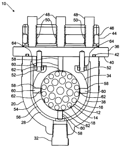
FIG. 1 is a side view in section of a housing for a flow conditioner with a
conditioner installed.
FIG. 2 is a side elevation view of the housing for a flow conditioner.
FIG. 3 is a perspective view of the body of the housing.
FIG. 4 is a side elevation view in section of the body of the housing.
FIG. 5 is a bottom plan view of the sealing portion of the plate carrier.
FIG. 6 is a top plan view of the clamp bar.
FIG. 7 is a perspective view of the flow conditioner carrying portion of the
plate
carrier.
FIG. 8 is a side elevation view in section of the flow conditioner carrying
portion
of the plate carrier.

DETAILED DESCRIPTION
[0007] A housing for a flow conditioner generally identified by reference
numeral 10 will
now be described with reference to FIG. 1 through 8.

[0008] Structure and Relationship of Parts:
[0009] Referring to FIG. 1, housing 10 for flow conditioner 12 is shown. Flow
conditioner 12 has a circular plate 14 having an outer perimeter 16 and flow
conditioning
apertures 18. Referring to FIG. 2, a body 20 of housing 10 has a first pipe
connection 22, a
second pipe connection 24 and a flow passage 26 between first and second pipe
connections
22 and 24. As depicted, first and second pipe connections 22 and 24 are
designed to be
attached to pipe sections by welding. However, it will be understood that
connections 22 and
24 could also be designed for other types of connections, such as threaded,
flanged, etc. as is
known in the industry. There is a carrier receiving cavity 28 within flow
passage 26, and an
opening 30 corresponding to carrier receiving cavity 28. As can be seen,
carrier receiving


CA 02675542 2009-08-19
3

cavity 28 has a larger diameter than flow passage 26. A pipe plug 32 is
located at the bottom
of carrier receiving cavity 28 to allow for cleanout, and to assist in
installing and removing
flow conditioner 12.

[0010] Referring to FIG. 1, a plate carrier 34 is used to hold flow
conditioner 12. Plate
carrier 34 has a sealing portion 36 and a flow conditioner carrying portion
38. Referring to
FIG. 5, sealing portion 36 has a sealing surface 40, which includes a seal 42,
for sealing
opening 30 that corresponding to carrier receiving cavity 28. Opening 30 can
be seen in FIG.
4. Referring to FIG. 2, sealing portion 36 is secured in place over opening 30
by using
connector, in this case, a clamp bar 44. Clamp bar 44 is inserted into a slot
46 in body 20, and
threaded pins 48 are inserted through holes 50 to apply downward pressure on
sealing portion
36 to secure plate carrier 34 within body 12 such that sealing surface 40
seals against body 20.
A top view of clamp bar 44 is shown in FIG. 7.

[0011] Referring to FIG. 1, flow conditioner carrying portion 38 depends from
sealing
portion 36. In the depicted embodiment, sealing portion 36 and flow
conditioner carrying
portion 38 are attached by screws 52. These portions may be otherwise
connected together,
or integrally formed. As will be seen below, a removable connection allows
easier access to
set screws 60, which are used to position flow conditioner 60. Referring to
FIG. 1 and 3, flow
conditioner carrying portion 38 is sized to be inserted through opening 30 and
into carrier
receiving cavity 28. Referring to FIG. 7 and 8, flow conditioner carrying
portion 38 has an
inner surface 54 for carrying flow conditioner 12 (as shown in FIG. 1) and an
outer surface
56. Inner surface 54 is designed to be substantially the same size as flow
passage 26 shown in
FIG. 4. Flow conditioner carrying portion 38 has a plurality of set screw
receiving apertures
58 extending from outer surface 56 to inner surface 54. Referring to FIG. 1,
this allows set
screws 60 to be inserted that can then be used to secure the position of flow
conditioner 12
within inner surface 54, and also center flow conditioner 12 relative to flow
passage 26.
Preferably, there are four set screw apertures 58 and screws 60, which allows
the position to
be easily adjusted vertically and horizontally, although this may also be
accomplished using
three apertures 58 and screws 60. Flow conditioner 12 preferably has small
recesses 62 that
correspond to set screws 60 that allow flow conditioner 12 to be gripped by
screws 60 against


CA 02675542 2009-08-19
4

fluid pressure along flow passage 26. Body 20 has machined tabs 64 in opening
30 that
maintain the horizontal position of flow conditioner 12 by holding the top of
flow conditioner
carrying portion 38.

[0012] Operation:
[0013] Referring to FIG. 3, body 20 is installed in a pipeline, generally
upstream of a
flow meter, by connecting first and second pipe connections 22 and 24 in a
pipeline. As
shown, connections 22 and 24 are designed to be welded, but may be designed
with threaded
or flanged connections. Once welded at connections 22 and 24, the only
possibility for
leakage is through opening 38, as body 20 is otherwise solid and closed.
Referring to FIG. 1,
plate carrier 34 is assembled by inserting flow conditioner 12 within flow
conditioner
carrying portion 38 and secured and centered by set screws 60. Flow
conditioner carrying
portion 38 is then attached to sealing portion 36. Once assembled, plate
carrier 34 is inserted
through opening 30 into cavity 28. Clamp bar 44 is slid into slot 46, and
threaded pins 48 are
insered to apply pressure to sealing portion 36 such that opening 30 is sealed
and plate carrier
34 is secured in place. As depicted, vertical position is maintained by the
contact between the
sealing surface 40 of sealing portion 36 and opening 30 of body 20. The
horizontal position is
maintained by the contact of the machined tabs 64 in opening 30 against the
top of flow
conditioner carrying portion 38.
[0014] Plate carrier 34 is removed for servicing or inspection by removing
clamp bar 44.
The depicted design allows a user to reposition flow conditioner carrying
portion 38 each
time it is removed, such that, once properly set, flow conditioner 12 will
remain in the same
position despite plate carrier 34 being removed and replaced.
[0015] Variations:
[0016] As an alternative to set screws 60, referring to FIG. 9, flow
conditioner carrying
portion 38 may be designed to have a closer fit, such that flow conditioner 12
is held in a
friction fit arrangement. In addition, a flange 66 may be provided on the
downstream side to
prevent flow conditioner 12 from becoming dislodged due to fluid pressure.


CA 02675542 2009-08-19

[0017] Referring to FIG. 10, a further alternative may have flow conditioner
12 integrally
formed with plate carrier 34. In this embodiment, flow conditioner carrier
portion 38 is
replaced with flow conditioner portion 68, with flow conditioning apertures 18
positioned
within portion 68 to properly align within flow passage 26 (shown in FIG. 4).
5
[0018] In this patent document, the word "comprising" is used in its non-
limiting sense to
mean that items following the word are included, but items not specifically
mentioned are not
excluded. A reference to an element by the indefinite article "a" does not
exclude the
possibility that more than one of the element is present, unless the context
clearly requires that
there be one and only one of the elements.

[0019] The following claims are to be understood to include what is
specifically
illustrated and described above, what is conceptually equivalent, and what can
be obviously
substituted. Those skilled in the art will appreciate that various adaptations
and modifications
of the described embodiments can be configured without departing from the
scope of the
claims. The illustrated embodiments have been set forth only as examples and
should not be
taken as limiting the invention. It is to be understood that, within the scope
of the following
claims, the invention may be practiced other than as specifically illustrated
and described.

Dessin représentatif
Une figure unique qui représente un dessin illustrant l'invention.
États administratifs

Pour une meilleure compréhension de l'état de la demande ou brevet qui figure sur cette page, la rubrique Mise en garde , et les descriptions de Brevet , États administratifs , Taxes périodiques et Historique des paiements devraient être consultées.

États administratifs

Titre Date
Date de délivrance prévu 2014-04-01
(22) Dépôt 2009-08-19
(41) Mise à la disponibilité du public 2011-02-19
Requête d'examen 2011-06-14
(45) Délivré 2014-04-01

Historique d'abandonnement

Il n'y a pas d'historique d'abandonnement

Taxes périodiques

Dernier paiement au montant de 263,14 $ a été reçu le 2023-07-06


 Montants des taxes pour le maintien en état à venir

Description Date Montant
Prochain paiement si taxe applicable aux petites entités 2024-08-19 253,00 $
Prochain paiement si taxe générale 2024-08-19 624,00 $

Avis : Si le paiement en totalité n'a pas été reçu au plus tard à la date indiquée, une taxe supplémentaire peut être imposée, soit une des taxes suivantes :

  • taxe de rétablissement ;
  • taxe pour paiement en souffrance ; ou
  • taxe additionnelle pour le renversement d'une péremption réputée.

Les taxes sur les brevets sont ajustées au 1er janvier de chaque année. Les montants ci-dessus sont les montants actuels s'ils sont reçus au plus tard le 31 décembre de l'année en cours.
Veuillez vous référer à la page web des taxes sur les brevets de l'OPIC pour voir tous les montants actuels des taxes.

Historique des paiements

Type de taxes Anniversaire Échéance Montant payé Date payée
Le dépôt d'une demande de brevet 400,00 $ 2009-08-19
Requête d'examen 800,00 $ 2011-06-14
Taxe de maintien en état - Demande - nouvelle loi 2 2011-08-19 100,00 $ 2011-06-14
Taxe de maintien en état - Demande - nouvelle loi 3 2012-08-20 100,00 $ 2012-05-23
Taxe de maintien en état - Demande - nouvelle loi 4 2013-08-19 100,00 $ 2013-08-16
Taxe finale 300,00 $ 2014-01-23
Taxe de maintien en état - brevet - nouvelle loi 5 2014-08-19 200,00 $ 2014-06-11
Taxe de maintien en état - brevet - nouvelle loi 6 2015-08-19 200,00 $ 2015-05-22
Taxe de maintien en état - brevet - nouvelle loi 7 2016-08-19 200,00 $ 2016-06-28
Taxe de maintien en état - brevet - nouvelle loi 8 2017-08-21 200,00 $ 2017-07-19
Taxe de maintien en état - brevet - nouvelle loi 9 2018-08-20 200,00 $ 2018-06-19
Taxe de maintien en état - brevet - nouvelle loi 10 2019-08-19 250,00 $ 2019-06-25
Taxe de maintien en état - brevet - nouvelle loi 11 2020-08-19 250,00 $ 2020-07-07
Taxe de maintien en état - brevet - nouvelle loi 12 2021-08-19 255,00 $ 2021-07-09
Taxe de maintien en état - brevet - nouvelle loi 13 2022-08-19 254,49 $ 2022-08-12
Taxe de maintien en état - brevet - nouvelle loi 14 2023-08-21 263,14 $ 2023-07-06
Titulaires au dossier

Les titulaires actuels et antérieures au dossier sont affichés en ordre alphabétique.

Titulaires actuels au dossier
CLARK, DEROLD G.
Titulaires antérieures au dossier
S.O.
Les propriétaires antérieurs qui ne figurent pas dans la liste des « Propriétaires au dossier » apparaîtront dans d'autres documents au dossier.
Documents

Pour visionner les fichiers sélectionnés, entrer le code reCAPTCHA :


Pour visualiser une image, cliquer sur un lien dans la colonne description du document. Pour télécharger l'image (les images), cliquer l'une ou plusieurs cases à cocher dans la première colonne et ensuite cliquer sur le bouton "Télécharger sélection en format PDF (archive Zip)" ou le bouton "Télécharger sélection (en un fichier PDF fusionné)".

Liste des documents de brevet publiés et non publiés sur la BDBC .

Si vous avez des difficultés à accéder au contenu, veuillez communiquer avec le Centre de services à la clientèle au 1-866-997-1936, ou envoyer un courriel au Centre de service à la clientèle de l'OPIC.


Description du
Document 
Date
(yyyy-mm-dd) 
Nombre de pages   Taille de l'image (Ko) 
Paiement de taxe périodique 2022-08-12 1 33
Abrégé 2009-08-19 1 21
Description 2009-08-19 5 216
Revendications 2009-08-19 2 86
Dessins 2009-08-19 6 121
Dessins représentatifs 2011-01-25 1 12
Page couverture 2011-02-02 2 48
Revendications 2013-05-21 1 22
Page couverture 2014-03-04 2 47
Correspondance 2009-09-14 1 28
Correspondance 2009-09-14 1 21
Correspondance 2009-08-18 17 519
Correspondance 2009-09-09 1 47
Correspondance 2009-09-21 9 289
Cession 2009-08-19 2 77
Correspondance 2011-03-31 3 162
Correspondance 2011-04-20 1 39
Correspondance 2011-04-27 1 12
Correspondance 2011-04-27 1 19
Poursuite-Amendment 2011-06-14 1 36
Taxes 2011-06-14 1 36
Correspondance 2011-06-16 1 76
Poursuite-Amendment 2013-01-07 2 85
Taxes 2013-08-16 1 33
Poursuite-Amendment 2013-09-17 7 129
Poursuite-Amendment 2013-05-21 4 68
Correspondance 2013-10-03 1 35
Correspondance 2014-01-23 1 35