Sélection de la langue

Search

Sommaire du brevet 2679148 

Énoncé de désistement de responsabilité concernant l'information provenant de tiers

Une partie des informations de ce site Web a été fournie par des sources externes. Le gouvernement du Canada n'assume aucune responsabilité concernant la précision, l'actualité ou la fiabilité des informations fournies par les sources externes. Les utilisateurs qui désirent employer cette information devraient consulter directement la source des informations. Le contenu fourni par les sources externes n'est pas assujetti aux exigences sur les langues officielles, la protection des renseignements personnels et l'accessibilité.

Disponibilité de l'Abrégé et des Revendications

L'apparition de différences dans le texte et l'image des Revendications et de l'Abrégé dépend du moment auquel le document est publié. Les textes des Revendications et de l'Abrégé sont affichés :

  • lorsque la demande peut être examinée par le public;
  • lorsque le brevet est émis (délivrance).
(12) Demande de brevet: (11) CA 2679148
(54) Titre français: PROCEDE ET SYSTEME AMELIORES D'EXTRACTION DU PETROLE BRUT
(54) Titre anglais: ENHANCED CRUDE OIL RECOVERY METHOD AND SYSTEM
Statut: Morte
Données bibliographiques
(51) Classification internationale des brevets (CIB):
  • E21B 43/24 (2006.01)
(72) Inventeurs :
  • DE BOER, SIEKO BEREND (Pays-Bas (Royaume des))
  • FLAMMA, JAN WILLEM (Pays-Bas (Royaume des))
  • LAMMERS, GERARD LEENDERT (Pays-Bas (Royaume des))
  • VANDEWEIJER, ANTONY ALOYSIUS HUBERTHUS (Pays-Bas (Royaume des))
  • VAN DER WERF, JOOST LAURENS (Pays-Bas (Royaume des))
  • ZEEMANS, HARKE JENTJE (Pays-Bas (Royaume des))
(73) Titulaires :
  • SHELL INTERNATIONALE RESEARCH MAATSCHAPPIJ B.V. (Pays-Bas (Royaume des))
(71) Demandeurs :
  • SHELL INTERNATIONALE RESEARCH MAATSCHAPPIJ B.V. (Pays-Bas (Royaume des))
(74) Agent: NORTON ROSE FULBRIGHT CANADA LLP/S.E.N.C.R.L., S.R.L.
(74) Co-agent:
(45) Délivré:
(22) Date de dépôt: 2009-09-18
(41) Mise à la disponibilité du public: 2010-03-22
Licence disponible: S.O.
(25) Langue des documents déposés: Anglais

Traité de coopération en matière de brevets (PCT): Non

(30) Données de priorité de la demande:
Numéro de la demande Pays / territoire Date
08164817.2 Office Européen des Brevets (OEB) 2008-09-22

Abrégés

Abrégé anglais


An enhanced crude oil recovery method comprises:
- injecting steam into a steam injection conduit (5)
which is retrievably arranged in a steam injection well
(1) ;

-inducing the steam to flow from the interior of steam
injection conduit (5) through gradually widening steam
injection channels (6) traversing the wall of the conduit
(5) into the surrounding formation (2); and

- producing crude oil heated by the injected steam from
the formation (2).

Revendications

Note : Les revendications sont présentées dans la langue officielle dans laquelle elles ont été soumises.


-6-


CLAIMS


1. An enhanced crude oil recovery method, comprising:

- injecting steam into a steam injection conduit which is
retrievably arranged in a steam injection well;

-inducing the steam to flow from the interior of steam
injection conduit through gradually widening steam
injection channels traversing the wall of the conduit
into the surrounding formation; and

- producing crude oil heated by the injected steam from
the formation.

2. The method of claim 1, wherein each gradually
widening steam injection channel comprises:

- a tubular inflow section in which a tubular steam
injection nozzle is arranged; and

- an expansion section, which provides a steam expansion
chamber for conveying steam from the nozzle into a space
between the outer surface of the steam injection conduit
and the inner surface of a at least partially permeable
well liner which is arranged within the steam injection
well.

3. The method of claim 1, wherein

- each gradually widening steam injection channel is
arranged in a side pocket in a thick walled section of
the steam injection conduit, which has a smaller internal
width than adjacent sections of the steam injection
conduit;

- the tubular inflow section of each steam injection
channel is drilled from an end face of the thick walled
section through the wall of the thick walled section in a
direction substantially parallel to the longitudinal axis


-7-


of the steam injection conduit; and
- the expansion section of each steam injection channel
is machined from the outer surface of the thick walled
section such that it intersects the tubular inflow
section.
4. The method of claim 3, wherein the expansion section
has a central axis which intersects or crosses the
longitudinal axis of the steam injection conduit at an
acute angle between 6 and 60 degrees relative to the
longitudinal axis.

5. The method of claim 4, wherein the steam injection
conduit is substantially coaxial to a surrounding at
least partially permeable well liner such that a
substantially annular space is present between the
conduit and liner, in which space an annular seal is
arranged at a location between a wellhead of the steam
injection well and the gradually widening steam injection
channels.

6. The method of any one of claims 1-5, wherein the
method further comprises converting the produced crude
oil into a transportation fuel and/or other chemical end
products.

7. An enhanced crude oil recovery system comprising
gradually widening steam injection channels traversing
the wall of a steam injection conduit, which is
configured to be retrievably arranged within a steam
injection well and to inject steam into a formation
surrounding the well.

8. The system of claim 7, wherein each gradually
widening steam injection channel comprises:

- a tubular inflow section in which a tubular steam
injection nozzle is arranged; and

- a expansion section, which intersects the tubular


-8-

inflow section and provides a steam expansion chamber for
conveying steam from the nozzle into a space between the
outer surface of the steam injection conduit and the
inner surface of a at least partially permeable well
liner which is arranged within the steam injection well.
9. The steam injection system of claim 8, wherein

- each gradually widening steam injection channel is
arranged in a side pocket in a thick walled section of
the steam injection conduit, which has a smaller internal
width than adjacent sections of the steam injection
conduit;

- the tubular inflow section of each steam injection
channel is drilled from an end face of the thick walled
section through the wall of the thick walled section in a
direction substantially parallel to the longitudinal axis
of the steam injection conduit; and

- the expansion section of each steam injection channel
is machined from the outer surface of the thick walled
section such that it intersects the tubular inflow
section.

10. The steam injection system of claim 8 or 9, wherein
the expansion section has a central axis which intersects
or crosses the longitudinal axis of the steam injection
conduit at an acute angle between 6 and 60 degrees
relative to the longitudinal axis.

Description

Note : Les descriptions sont présentées dans la langue officielle dans laquelle elles ont été soumises.


CA 02679148 2009-09-18
TS 6915

- 1 -

ENHANCED CRUDE OIL RECOVERY METHOD AND SYSTEM
BACKGROUND OF THE INVENTION

The invention relates to an enhanced crude oil
recovery method and system, wherein steam is injected
into a crude oil containing underground formation for

enhancing crude oil production therefrom.

Such a method and system are known from US patent
6,158,510. In the system known from this prior art
reference a steam injection conduit with radial steam
injection holes is arranged within a blank section of a

well liner, such that steam is injected radially into the
annular space between the steam injection conduit and the
well liner and is then deflected to perforated sections
of the well liner, that are surrounded by sandscreens,
through which the steam is injected from the annular

space into the surrounding formation.

A disadvantage of the known system is that the radial
steam injection holes and surrounding blank section of
the well liner are prone to erosion and corrosion by the
flux of hot steam, in particular if the steam injection

conduit is not co-axial to the well liner, and that it is
difficult to maintain a substantially equal steam flux
through each of the holes at varying conditions.
It is an object of the present invention to alleviate
these disadvantages and to provide a retrievable and

reconfigurable steam injection system and method in which
steam injection channels can be configured such that
erosion of the channels is reduced and such that an
accurately determined and constant flux of steam can be

injected through the channels into the surrounding
formation.

DOCSMTL: 3422402\1


CA 02679148 2009-09-18
- 2 -
SUMMARY OF THE INVENTION
In accordance with the invention there is provided an
enhanced crude oil recovery method, comprising:

- injecting steam into a steam injection conduit which is
retrievably arranged in a steam injection well;

-inducing the steam to flow from the interior of steam
injection conduit through gradually widening steam
injection channels traversing the wall of the conduit
into the surrounding formation; and

- producing crude oil heated by the injected steam from
the formation.

The steam injection conduit may be substantially
coaxial to a surrounding at least partially permeable
well liner such that an substantially annular space is

present between the conduit and liner, in which space an
annular seal may be arranged at a location between the
wellhead and the gradually widening steam injection
channels.

In accordance with the invention there is furthermore
provided a steam injection system comprising gradually
widening steam injection channels traversing the wall of
a steam injection conduit, which is configured to be
retrievably arranged within a steam injection well and to
inject steam into a formation surrounding the well.
Each gradually widening steam injection channel
preferably comprises:
- a tubular inflow section in which a tubular steam
injection nozzle is arranged; and

- an expansion section, which intersects the tubular
inflow section and provides a steam expansion chamber for
conveying steam from the nozzle into a space between the
outer surface of the steam injection conduit and the
DOCSMTL: 3422402\1


CA 02679148 2009-09-18
- 3 -

inner surface of a at least partially permeable well
liner which is arranged within the steam injection well.
It is furthermore preferred that:

- each gradually widening steam injection channel is

arranged in a side pocket in a thick walled section of
the steam injection conduit, which has a smaller internal
width than adjacent sections of the steam injection
conduit;
- the tubular inflow section of each steam injection

channel is drilled from an end face of the thick walled
section through the wall of the thick walled section in a
direction substantially parallel to the longitudinal axis
of the steam injection conduit;

- the expansion section of each steam injection channel
is machined from the outer surface of the thick walled
section such that it intersects the tubular inflow

section; and
- the expansion section has a central axis which
intersects or crosses the longitudinal axis of the steam
injection conduit at an acute angle between 6 and 60

degrees relative to the longitudinal axis.

These and other features, embodiments and advantages
of the method and/or system according to the invention
are described in the accompanying claims, abstract and
the following detailed description of preferred
embodiments disclosed in the accompanying drawing in
which reference numerals are used which refer to
corresponding reference numerals that are shown in the
drawing.

BRIEF DESCRIPTION OF THE DRAWING

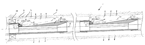
Fig.l is a schematic longitudinal sectional view of a
steam injection well, which is equipped with steam
injection system according to the invention.

DOCSMTL: 3422402\1


CA 02679148 2009-09-18
- 4 -

DETAILED DESCRIPTION OF THE DEPICTED EMBODIMENT
Fig.l shows a steam injection well 1, which comprises
a substantially horizontal lower section that traverses a
viscous crude oil containing underground formation 2.

The depicted lower section of the well 1 comprises a
at least partially permeable well liner 3, which
comprises a series of perforations 4 and contains a
retrievable steam injection conduit 5.

The conduit 5 comprises a series of gradually expanding
steam injection channels 6 for conveying steam from the
interior of the steam injection conduit 5 into the
annular space 7 between the steam injection conduit 5 and
well liner 3. The steam injection channels 6 are arranged
in thick walled sections 5A of the steam injection

conduit 5, which each have a smaller internal width than
adjacent large diameter sections 5B and 5C of the steam
injection conduit. Each steam injection channel 6
comprises a longitudinal tubular inflow section 6A, which
is drilled from an end face 9 of the thick walled section

5A through the wall of the thick walled section 5A in a
direction substantially parallel to the longitudinal axis
8 of the steam injection conduit 5.

A steam injection nozzle 6B is inserted within each
longitudinal tubular inflow section 6A.
Each steam injection channel 6 furthermore comprises
and an inclined expansion section 6C, which provides a
steam expansion chamber and which is machined from the
outer surface of the thick walled section 5B such that a
central axis 10 of the expansion section 6C intersects a

central axis 11 of the longitudinal tubular inflow
section 6A at an acute angle a.

Each expansion section 6C has a central axis 10 which
is intersects or crosses the longitudinal axis 8 of the
DOCSMTL: 3422402\ I


CA 02679148 2009-09-18
-

steam injection conduit 5 at an acute angle a between 6
and 60 degrees. In the embodiment shown the steam
injection conduit 5 is substantially coaxial to the well
liner 3 so that the longitudinal axis 8 of the steam

5 injection conduit 5 substantially coincides with the
longitudinal axis of the well liner 3. In the embodiment
shown the steam injection nozzle is oriented
substantially co-axial to the longitudinal axis 8 of the
steam injection conduit 5 and the angle a is shown as the

angle between the central axis 11 of the steam injection
nozzle and the central axis 10 of the expansion section
6C of each steam injection channel 6. A seal 12 is
arranged in the substantially annular space 7 between the
steam injection conduit 5 and the well liner 3 at a

location between the wellhead (not shown) and the series
of gradually widening injection channels 6. Optionally
additional seals are arranged in the annular space 7
between adjacent steam injection channels 6.

Optionally the expansion section 6C may be arranged
within a blank section of the well liner 3, such that
steam is injected at an acute angle a into the annular
space between expansion section 6C and the well liner 3
and is then deflected to perforations 4 in the well liner
3, that are surrounded by sandscreens (not shown),
through which the steam is injected from the annular
space into the surrounding formation 2.

DOCSMTL: 3422402\1

Dessin représentatif
Une figure unique qui représente un dessin illustrant l'invention.
États administratifs

Pour une meilleure compréhension de l'état de la demande ou brevet qui figure sur cette page, la rubrique Mise en garde , et les descriptions de Brevet , États administratifs , Taxes périodiques et Historique des paiements devraient être consultées.

États administratifs

Titre Date
Date de délivrance prévu Non disponible
(22) Dépôt 2009-09-18
(41) Mise à la disponibilité du public 2010-03-22
Demande morte 2013-09-18

Historique d'abandonnement

Date d'abandonnement Raison Reinstatement Date
2011-09-19 Taxe périodique sur la demande impayée 2011-09-30
2012-09-18 Taxe périodique sur la demande impayée

Historique des paiements

Type de taxes Anniversaire Échéance Montant payé Date payée
Le dépôt d'une demande de brevet 400,00 $ 2009-09-18
Rétablissement: taxe de maintien en état non-payées pour la demande 200,00 $ 2011-09-30
Taxe de maintien en état - Demande - nouvelle loi 2 2011-09-19 100,00 $ 2011-09-30
Titulaires au dossier

Les titulaires actuels et antérieures au dossier sont affichés en ordre alphabétique.

Titulaires actuels au dossier
SHELL INTERNATIONALE RESEARCH MAATSCHAPPIJ B.V.
Titulaires antérieures au dossier
DE BOER, SIEKO BEREND
FLAMMA, JAN WILLEM
LAMMERS, GERARD LEENDERT
VAN DER WERF, JOOST LAURENS
VANDEWEIJER, ANTONY ALOYSIUS HUBERTHUS
ZEEMANS, HARKE JENTJE
Les propriétaires antérieurs qui ne figurent pas dans la liste des « Propriétaires au dossier » apparaîtront dans d'autres documents au dossier.
Documents

Pour visionner les fichiers sélectionnés, entrer le code reCAPTCHA :


Pour visualiser une image, cliquer sur un lien dans la colonne description du document. Pour télécharger l'image (les images), cliquer l'une ou plusieurs cases à cocher dans la première colonne et ensuite cliquer sur le bouton "Télécharger sélection en format PDF (archive Zip)" ou le bouton "Télécharger sélection (en un fichier PDF fusionné)".

Liste des documents de brevet publiés et non publiés sur la BDBC .

Si vous avez des difficultés à accéder au contenu, veuillez communiquer avec le Centre de services à la clientèle au 1-866-997-1936, ou envoyer un courriel au Centre de service à la clientèle de l'OPIC.


Description du
Document 
Date
(yyyy-mm-dd) 
Nombre de pages   Taille de l'image (Ko) 
Dessins représentatifs 2010-02-24 1 17
Abrégé 2009-09-18 1 14
Description 2009-09-18 5 201
Revendications 2009-09-18 3 106
Dessins 2009-09-18 1 32
Page couverture 2010-03-15 1 46
Correspondance 2009-11-02 3 86
Correspondance 2010-03-12 1 18
Correspondance 2009-10-19 1 18
Cession 2009-09-18 4 157
Correspondance 2010-01-22 5 188
Correspondance 2010-04-29 2 89
Taxes 2011-09-30 2 67