Note : Les descriptions sont présentées dans la langue officielle dans laquelle elles ont été soumises.
CA 02685874 2009-10-30
1
Title of Invention
OPEN/CLOSE CONTROL SYSTEM FOR INSPECTION LID
Technical Field
[0001] The present invention relates to emergency release means such
as an emergency release cock for allowing a side entrance/exit door of a
railway vehicle to be manually opened and in particular relates to an
open/close control system for an inspection lid (an access cover) for
controlling opening/closing of the inspection lid in a wall surface inside
which an emergency release means is installed.
Background Art
[0002] For instance, a railway vehicle is configured such that a side
entrance/exit door provided in a side body frame is opened/closed by an air
cylinder in which air supplied thereto is pressurized during traveling to
keep the entrance/exit door in a closed state. In case of emergence, it is
necessary for passengers to open the door to freely go outside. In the
railway vehicle, therefore, an emergency release cock is provided to release
the air to thereby allow opening/closing of the door. This emergency
release cock is installed for example inside a wall surface with an
inspection lid in the vicinity of the door.
[0003] However, the emergency release cock is easily accessible by every
person. Patent Literature 1 listed below therefore proposes an emergency
release cock configured not to operate during traveling. Specifically, a
locking device for restringing rotation of a handle is provided near the
emergency release cock and a box-shaped keyhole is provided in an end of
the handle on an operating side, respectively. By excitation of a locking
solenoid, a lock pin is inserted in the keyhole to restrict the rotation of
the
CA 02685874 2009-10-30
2
handle.
Citation List
Patent Literature 1: JP 2002-347616 A
Summary of Invention
Technical Problem
[0004] Meanwhile, the conventional emergency release cock the
operation of which is disabled during traveling as above could achieve an
object for suppressing mischief at a certain level. However, a simple
structure that restricts rotation of the emergency release cock is considered
insufficient for suppressing more malicious mischief. Because it is
conceivable that a person who maliciously opens the inspection lid
sometimes may easily abandon malicious or mischievous access to the
emergency release cock in face thereof, whereas sometimes may break
down the locking device. During vehicle traveling, therefore, it is
originally considered effective in disabling opening of the inspection lid
that closes the space in which the cock is placed. In case of emergency, on
the other hand, it is necessary to reliably enable opening of the cock in a
safe condition where the vehicle is stopped. Such problem may occur not
only in the case where the air cylinder is used as a door engine, but also in
the case where an electric actuator is used. In this case, energization to
the electric actuator is stopped to allow the side entrance/exit door to be
opened and closed. Thus, the same applies to an emergency release
switch or the like placed inside the inspection lid.
[0005] The present invention has been made to solve the above
problems and has a purpose to provide an open/close control system for an
CA 02685874 2009-10-30
3
inspection lid adapted not to open while a vehicle travels.
Solution to Problem
[0006] An open/close control system for inspection lid according to the
present invention, there is provided an open/close control system for
inspection lid, including emergency release means that disables power
transmission of drive means for opening and closing a side entrance/exit
door of a railway vehicle, the emergency release means being installed in a
space inside a wall surface of the vehicle, the space being opened and
closed by the inspection lid, the system comprising: a locking device
provided in the space inside the wall surface to restrict rotation of the
inspection lid; and an open/close control device for detecting traveling of
the railway vehicle and operating the locking device.
[0007] In the open/close control system for inspection lid according to
the invention, preferably, the locking device includes: a lock plate fixed on
the inside of the inspection lid; and a locking solenoid that causes a lock
pin to protrude by a solenoid to restrict rotation of the inspection lid
through the lock plate.
In the open/close control system for inspection lid according to the
invention, preferably, the locking solenoid includes an urging member to
retreat the lock pin.
In the open/close control system for inspection lid according to the
invention, preferably, the open/close control device is configured to receive
a detection signal from a speed sensor and operate the locking device based
on a fixed speed.
Furthermore, in the open/close control system for inspection lid
according to the invention, preferably, the drive means is an air cylinder or
an electrical actuator, and the emergency release means is an emergency
CA 02685874 2009-10-30
4
release cock for releasing working air from the air cylinder to the
atmosphere or an emergency release switch for shutting off energization to
the electrical actuator from a power supply coupled thereto.
Advantageous Effects of Invention
[00081 According to the open/close control system for inspection lid
according to the invention, the inspection lid is locked and disabled from
opening during vehicle traveling, but the inspection lid is unlocked and
enabled to open during vehicle stop. Therefore, even if a person attempts
to touch the emergency release means such as an emergency release cock
and an emergency release switch with malicious or mischievous intent
during vehicle traveling, the inspection lid disabled from opening makes
the person abandon such intent. It is therefore effective in suppressing
operation of the emergency release means during traveling. In case of
emergency such as fires, the inspection lid is unlocked while the vehicle is
stopped so that the emergency release means can be operated for safe
escape.
[00091 The present invention provides a simple configuration that the
lock pin is caused to protrude by the solenoid to interfere with the lock
plate to block rotation of the inspection lid. Thus, the above effect can be
achieved at low cost. With such simple configuration, the lock pin is
unlikely to become snagged on the lock plate when the inspection lid is
unlocked, thereby reliably enabling operation of the emergency release
cock after unlocking. In particular, the inspection lid may be forcibly
unlocked by the urging member to more reliably enable the operation of
the emergency release cock.
Brief Description of Drawings
CA 02685874 2009-10-30
[00101 FIG. 1 is a perspective view showing an emergency release cock
and a locking device provided in the space inside a wall surface of a
railway vehicle;
FIG. 2 is a side view of the emergency release cock and the locking
5 device provided in the space inside the wall surface of the railway vehicle
seen from a direction indicated by an arrow A in FIG. 1;
FIG. 3A is an enlarged view of a locking solenoid shown in FIG. 2;
FIG. 3B is an enlarged view of the locking solenoid shown in FIG.
1; and
FIG. 4 is a diagram of an electrical circuit for controlling locking
operations of the locking solenoid.
Reference Signs List
[00111
1 Emergency release cock
2 Wall
5 Inspection lid
7 Lock plate
10 Locking solenoid
11 Solenoid
18 Lock pin
19 Return spring
21 Controller
Description of Embodiments
[00121 A detailed description of a preferred embodiment of an open/close
control system for inspection lid embodying the present invention will now
be given referring to the accompanying drawings.
CA 02685874 2009-10-30
6
For each side entrance/exit door formed in side body frames of a
railway vehicle, for example, an air cylinder is used as a door engine and
an electromagnetic valve is controlled by an open/close switch in a driver's
cabin or the like to supply and discharge high-pressure working air with
respect to the air cylinder of each side entrance/exit door. In association
with this extension and contraction of the air cylinders, therefore, the
doors are controlled together to open and close. On the other hand, an
emergency release cock is provided to release air pressure in the air
cylinder to the atmosphere in order to allow the door to be opened
manually in case of emergency.
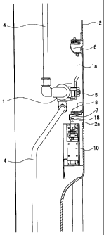
[00131 Herein, FIG. 1 is a perspective view showing the emergency
release cock and a locking device provided in the space inside a wall
surface of the railway vehicle. FIG. 2 is a side of the emergency release
cock and locking device provided in the space inside the wall surface, seen
from a direction indicated by an arrow A in FIG. 1.
An emergency release cock 1 that enables manual opening of the side
entrance/exit door is installed in the space inside the wall surface 2 and
located in front of an opening 2a formed in the wall surface 2. The
emergency release cock 1 is connected to an air pipe 4 to release the air
pressure supplied to the air cylinder that closes the door to the atmosphere.
The cock 1 is provided with a handle la in face of the opening 2a. By
90 -rotation of the handle la, a valve is switched to open or close.
[00141 In the opening 2a of the wall surface 2, an inspection lid 5 is
provided so as to be normally closed, forming a part of the wall surface 2.
Accordingly, the presence of the cock 1 is usually confirmed by a name
plate placed near the inspection lid 5 but the cock is out of passengers'
sight. In emergency, however, the inspection lid 5 is opened by a
passenger and the handle la is turned to open the valve of the emergency
CA 02685874 2009-10-30
7
release cock 1. Thus, working air is released from the air cylinder,
allowing the door to be manually opened. In this embodiment, for the
purpose of enabling the above operation of the emergency release cock 1
only during vehicle stop, the locking device is adapted to disable the
inspection lid 5 from opening during vehicle traveling.
[0015] The opening 2a of the wall surface 2 is defined by an inwardly
bent peripheral edge portion as shown in FIG. 2, with which an outer
peripheral portion of the inspection lid 5 is placed in contact so that the
wall surface 2 and the inspection lid 5 are flush with each other. A hinge
member 6 is fixed on the inside of an upper end of the inspection lid 5 and
attached to pivotable about a pin. Accordingly, a passenger who stands in
front of the wall surface 2 can pick and pull a lower end of the inspection
lid 5 to open the opening 2a. The locking device is configured to restrict
the rotation of the inspection lid 5 held in a closed state.
[0016] The inspection lid 5 is provided with a lock plate 7 made of metal
bent at a right angle and fixed on the inside of a lower end portion of the
lid 5. The lock plate 7 is apt to be deformed by forced opening of the
inspection lid 5. For easy replacement, therefore, the lock plate 7 is
secured with screws to a base 8 fixed to the inspection lid 5. A locking
solenoid 10 is provided for this lock plate 7. In the locking solenoid 10, a
lock pin 18 is coaxially fixed to a plunger 13 and protrudes upward.
Herein, FIG. 3A is an enlarged view of the locking solenoid 10 shown in
FIG. 2 and FIG. 3B is another enlarged view of the locking solenoid 10
shown in FIG. 1.
[0017] The locking solenoid 10 integrally includes a solenoid 11 which is
a wound coil set in a magnetic frame 12. Two terminals are extended
from the coil. In the solenoid 11, the plunger 13 is inserted in the coil and
moved upward by energization to the solenoid 11. The magnetic frame 12
CA 02685874 2009-10-30
8
is fixed to a cover frame 14 to assemble the solenoid 11 with the cover
frame 14. The cover frame 14 surrounds an upper part of the solenoid 11.
In the cover frame 14, a guide plate 15 is fixed. A lock pin 18 is placed
passing through the cover frame 14 and the guide plate 15.
[0018] The lock pin 18 is coaxially coupled to the plunger 13 by a
coupling nut 16 and fixed with a spring retaining flange 17 above the guide
plate 15. One end of the return spring 19 placed around the lock pin 18
abuts the flange 17. The other end of the return spring 19 abuts a ceiling
plane of the cover frame 14 to urge the lock pin 18 downward. Thus, the
locking solenoid 10 is configured such that when the solenoid 11 is
energized, the lock pin 18 is moved up to a position indicated by a chain
double-dashed line against the urging force of the return spring 19.
During non-energization, on the other hand, even though the plunger 13 is
moved downward by its own weight, the plunger 13 is forcibly pressed
down by the urging force of the return spring 19 so as to reliably move
down even when the lock pin 18 gets snagged on the lock plate 7 or
something else.
[0019] The above locking solenoid 10 is mounted in the internal space
inside the wall surface 2 directly below the opening 2a so that the lock pin
18 caused to protrude upward by energization to the solenoid 11 interferes
with the lock plate 7. In the open/close control system in this embodiment,
opening/closing of the inspection lid 5 is controlled by operation of the
locking solenoid 10. In this embodiment, particularly, the inspection lid 5
is locked during vehicle traveling and unlocked during stop.
[0020] FIG. 4 is a diagram showing an electrical circuit for controlling
locking operations of the locking solenoids 10. An electrical circuit 20 for
controlling the locking solenoids 10 includes a controller 21 to receive a
signal from a speed sensor not shown. For instance, this speed sensor is
CA 02685874 2009-10-30
9
configured to detect a speed of 5 km per hour and generate a speed signal.
In this embodiment, therefore, upon receipt of the speed signal
representing 5 km per hour, the controller 21 activates a speed relay 22.
This speed of 5 km per hour is a value observable just after the start of
traveling or just before the stop of traveling. Based on this speed signal,
therefore, a traveling state and a stop state of the railway vehicle can be
substantially confirmed.
[0021] In the railway vehicle, circuit blocks are provided one in each
vehicle body, each of the circuit block including a speed signal transfer
relay 23 and switches 24 for the solenoids 11 of the locking solenoids 10.
The locking solenoids 10 are provided one for each door and hence the
switches 24 are provided one for each locking solenoid 10. Accordingly,
the switches 24 are switched together ON/OFF by the speed signal transfer
relay 23. When the speed relay 22 having an a-contact (a make-contact) is
turned ON, the speed signal transfer relays 23 in the whole railway vehicle
are energized. In association with this operation, the switches 24 at the
contact "a" are also turned ON, thereby energizing the solenoids 11.
[0022] The following explanation is given to the operations of the
open/close control system for inspection lid in this embodiment. When the
railway vehicle starts to travel, the speed signal is transmitted from the
speed sensor to the controller 21, which determines that the vehicle has
entered a traveling state. As mentioned above, the speed sensor
transmits the speed signal at the time when the speed exceeds 5 km per
hour. However, it is a very short time before the speed reaches 5 km per
hour and hence that signal substantially indicates the start of traveling.
Upon the start of traveling of the railway vehicle, accordingly, the
controller 21 turns on the speed relay 22 to energize each speed signal
transfer relay 23, thereby turning on each switch 24 to energize each
CA 02685874 2009-10-30
solenoid 11 of each locking solenoid 10.
[00231 When each solenoid 11 is energized, the plunger 13 in each
locking solenoid 10 is moved upward against the urging force of the return
spring 19, thus causing the lock pin 18 to protrude upward. An upper end
5 portion of the lock pin 18 moves up to a position corresponding to the lock
plate 7. Even if the inspection lid 5 is attempted to be opened for
operation of the emergency release cock 1 during traveling, the lock plate 7
is blocked by the lock pin 18, thus not allowing the inspection lid 5 to
rotate any more. Consequently, the inspection lid 5 is held in a closed
10 state during traveling, disabling operation of the cock 1. The side
entrance/exit door is not allowed to be opened.
[00241 When the traveling vehicle is stopped, on the other hand, the
speed signal from the speed sensor is transmitted to the controller 21,
which determines that the vehicle has been stopped. At that time, the
speed relay 22 is turned off by the controller 21 as shown in FIG. 4 to shut
off energization to the speed signal transfer relays 23. Accordingly, each
switch 24 is also turned off, shutting off energization to each solenoid 11.
The plunger 13 is pressed down by the urging force of the return spring 19,
moving the lock pin 18 down to a position in which the lock pin 18 does not
interfere with the lock plate 7. Thus, the inspection lid 5 is unlocked.
[00251 In case of emergency such as fires, in which the side
entrance/exit door has to be opened, the inspection lid 5 can be opened in
such a manner that the inspection lid 5 is rotated upward about the hinge
member 6 on the inside of the upper end. Since the emergency release
cock 1 is installed with the handle la placed closer to the opening 2a
formed in the wall surface 2, the handle la is turned to freely open the
corresponding door. On the other hand, even in the case other than
emergency, the inspection lid 5 can be opened only while the vehicle is
CA 02685874 2009-10-30
11
stopped. In the open/close control system for inspection lid, therefore, for
example a limit switch not shown for detecting opening/closing of the
inspection lid 5 is provided to prevent the inspection lid 5 from remaining
opened during traveling. This ensures that the inspection lid 5 is held in
a closed state during traveling.
[0026] According to the open/close control system for inspection lid in
this embodiment, the inspection lid 5 is locked and disabled from opening
as long as the railway vehicle is running. Even if a person attempts to
touch the emergency release cock 1 with malicious or mischievous intent,
such action is prevented in advance. It is therefore effective in
suppressing operation of the emergency release cock 1 during traveling.
Even in a case with no malicious or mischievous intent, furthermore,
in emergency situations such as fires, a passenger conceivably opens the
side entrance/exit door during traveling to scramble to escape. Disabling
operation of the emergency release cock 1 other than during vehicle stop is
thus effective for safe escape.
[0027] If the inspection lid 5 is forcibly opened, the lock plate 7 may get
snagged on the lock pin 18, not allowing the plunger 13 to be moved down
even after energization to the solenoid 11 is shut off. The inspection lid 5
thus remains unlocked. In this embodiment, however, the lock pin 18 is
forcibly moved down by the return spring 19. When the railway vehicle is
stopped, the emergency release cock 1 is reliably enabled to be operated.
[0028] Furthermore, the simple configuration allows the lock pin 18 to
protrude upward by the solenoid 11 and interfere with the lock plate 7,
thereby disabling the rotation of the inspection lid 5. The aforementioned
effects can therefore be achieved at low cost. With such simple
configuration, the lock pin 18 is unlikely to get snagged on the lock plate 7,
thus ensuring unlocking of the inspection lid 5 to perform the operation of
CA 02685874 2009-10-30
= 12
the emergency release cock 1 during vehicle stop. Moreover, the lock pin
18 is forcibly moved down by the return spring 19 to unlock the inspection
lid 5 and thus manipulation of the emergency release cock 1 is reliably
enabled during vehicle stop.
Industrial Applicability
[00291 The open/close control system for inspection lid according to the
invention is explained above as one embodiment, but the present invention
may be embodied in other specific forms without departing from the
essential characteristics thereof.
In the above embodiment, the locking device is constituted of the lock
plate 7 and the locking solenoid 10. An alternative may be configured by
for instance an air cylinder or the like instead of the locking solenoid 10.
In the above embodiment, the speed sensor is used to detect a vehicle
traveling state. The sensor may be any sensor if only it can detect
traveling and stop.
In the above embodiment, the railway vehicle using the air cylinder as
the door engine is exemplified. The invention may be applied to
inspection lids for covering emergency release switches mounted in a
railway vehicle configured to open/close side entrance/exit doors by an
electrical actuator.
[00301 The invention is applied to the inspection lid for covering
emergency release means for the side entrance/exit door is placed.
Furthermore, the locking device may be provided for another lid in a
railway vehicle to restrict opening/closing of the lid so that the locking
device is controlled according to traveling of the railway vehicle.