Note : Les descriptions sont présentées dans la langue officielle dans laquelle elles ont été soumises.
CA 02690465 2009-12-10
SPECIFICATION
BUS208CT
FASTENER FOR DETACHABLY CONNECTING
A PROFILE TO A COUNTER PROFILE
The invention is directed to a fastener for disengageably connecting of a
profile to a counter profile. The counter profile exhibits an undercut groove
and the
profile exhibits a receiver for a housing of the fastener. An eccentric bolt
is rotary
supported in the housing, wherein the eccentric bolt in addition to the cam
disk
disposed in the interior of the case also exhibits a bolt head projecting from
the
housing and serves for the actuation of rotation of the eccentric bolt. A
plate is
disposed in the housing, wherein the plate is longitudinally shiftable by the
cam disk
between a pullout position and a plug in position. At least one hook is
disposed at
the outer end of the plate, wherein the hook projects from the housing. There
is a
bevel at the plate running inclined to the longitudinal shifting, wherein the
plate is
supported at a contact point of the housing. This has the consequence that
upon
plugging in the hook runs cross behind the groove wall in the counter profile.
An
inner section at the plate is penetrated by the eccentric bolt.
Such a fastener is known from the German printed Patent document DE
3128595. The known case of the fastener is formed as a box with at least
regionally
AMENDED SHEET
Dieter Hackenberg PCT/EP2008/003682
CA 02690465 2009-12-10
walls on all sides, apart from breakouts for mounting its individual
components
together, and therefore has to be produced by injection molding, for example
by zinc
die casting.
Although the known fastener has proven its value, in some application cases
there is noticed an insufficient strength of the fastener. In addition
production and
assembly costs of the fastener are undesirably high.
Another fastener is shown in the document WO 97/25536, namely a clamping
device for the disengageable connecting of two profile pieces. The housing of
this
device however is composed of several individual components, which components
have to be put together with a relatively high expenditure. The composing
occurs
with screws or rivets, wherein also an insufficient strength is generated.
However,
here also the costs are undesirably high based on the assembly.
The same holds for the fastening device of the German printed Patent
document DE 3607849. The side walls are furnished open in this device, which
leads to further loss in stability as was the case in the precedingly recited
devices.
The high costs of an assembly through the multiple part construction of the
housing
are here also present.
AMENDED SHEET
Dieter Hackenberg PCT/EP2008/003682
CA 02690465 2009-12-10
It is an object of the present invention to develop a fastener of the kind
indicated in the preamble of claim 1, which fastener is economically and
distinguishes itself by a high strength. This is accomplished according to the
present
invention by the features recited in claim 1, which features have the
following special
importance.
According to the present invention, the fastener is a single piece housing
open
on two end sides, wherein the housing is generated by multiple bending of a
sheet
metal blank. In fact, a suitable working material with a sufficient high
strength can
be employed as material for the sheet metal blank. In particular, steel has
proven
itself here. The sheet metal ends of the sheet metal blank, abutting against
each other
and generated during bending of the case, are connected to each other, wherein
the
connection is directed opposite to a widening of the case resulting from
overturning
of the cam disk. A bending off of the angles from the sheet metal blank is
thereby
prevented in the case and the shape of the case is thereby stabilized. This
feature
results in a surprisingly high strength. At least at the front case end at
least a first
angling off of wall end pieces is furnished in order to generate a contact
point for the
plate bevel.
An economic production of the case with a high strength can be achieved at
least in cases where the two sheet metal ends are held together by shape
matching
AMENDED SHEET
Dieter Hackenberg PCT/EP2008/003682
CA 02690465 2009-12-10
~
and, as proposed in claim 2, exhibit two formed edges running in the
longitudinal
direction of the case, wherein the two formed edges have a border profile
undercut
and complementary to each other. Then there is present a face flush shape
matching
connection. One obtains a space saving smooth contour of the case, wherein the
contour of the case can be introduced without problem into a correspondingly
small
dimensioned receiver in the profile to be connected.
A leaf spring is disposed at the inner end of the plate according to an
embodiment example, wherein the leaf spring presses outwardly the bolt head
cross
to the longitudinal shifting direction and out of the case. A cross force
effective at
the bolt head and cross directed is thereby generated. A so-called pushbutton
mounting and pushbutton demounting is thereby possible. The free end of the
leaf
spring supports itself at an inner face of the case and slides along this
support face
upon longitudinal shifting of the plate. The leaf spring end assumes two
extreme
positions during the longitudinal shifting. There is a starting position,
which is
present in the pullout position of the plate. The peculiarity of this
embodiment
example comprises that the support face for the leaf spring end is furnished
with a
rising ramp at least in certain regions, wherein the ramp gets higher in the
direction
of the final position. The leaf spring end rests on the ramp in the final
position. A
longitudinally directed longitudinal force effective in the pullout sense is
generated
AMENDED SHEET
Dieter Hackenberg PCT/EP2008/003682
CA 02690465 2009-12-10
between the inclined leaf spring end the ramp, wherein the longitudinal force
acts on
the plate. The latter has the following consequences.
The case as well as the plate with its hooks and its bevels are preferably
comprising steel for reasons of strength. Problems exist between the bevels of
the
plates and their housing contact positions during the pullout motion of the
plate. The
bevels of the plates slide only heavily at the contact positions of the case
based on
unfavorable friction values. Operational disturbances occur when one wishes to
transfer the hook at the plate from its plug in position into a pullout
position. Since
however a longitudinal force acting in the pullout sense is generated in the
plate
according to the present invention, this longitudinal force can advance the
sliding
motion of the bevel of the plate. This longitudinal force supports the push
force
generated by the cam disk. The means for this longitudinal force of the plate
are
equally self generated, that is by the contact between the inclined leaf
spring and the
ramp. Since such a ramp can be generated simply by a dent in the wall of the
case,
the present invention does need neither additional device components nor
additional
space. Neither the handling nor the assembling or disassembling are interfered
with
by the recited inventive steps. It is decisive that the fastener according to
the present
invention as mentioned is easily actuable and operates reliably.
AMENDED SHEET
Dieter Hackenberg PCT/EP2008/003682
CA 02690465 2009-12-10
Additional steps and advantages of the invention result from the further
claims,
the description and drawings. The invention is represented by four embodiment
examples in the drawings. A first embodiment example is shown in figures 1
through 14, wherein the plate of the fastener is subdivided into four tongues
with
four hooks in its outer end region and therefore forms a four hook fastener.
There is
shown in detail:
Figures 1 through 3 show the front view, the rear view and the top planar view
onto such a four hook fastener, wherein the plate is disposed in a push out
position,
Figures 4 through 6 show the same four hook fastener in the analogous front
view, rear view and top planar view, wherein the plate is disposed in its plug
in
position in the housing,
Figure 7 shows the top planar view onto the demounted plate of the four hook
fastener of figures 1 through 6,
Figure 8 shows a top planar view onto the plate of figure 7,
Figure 9 shows the perspective view of the plate of figures 7 or 8,
Figure 10 shows a longitudinal section through the housing of the four hook
fastener shown in figures 1 through 6 along the section line X - X of figure
11,
AMENDED SHEET
Dieter Hackenberg PCT/EP2008/003682
CA 02690465 2009-12-10
Figure 1 1 shows a top planar view onto the case shown in figure 10,
Figure 12 shows a cross-sectional view of the case shown in figure 1 1 along
the section line XII - XII shown in figure 11,
Figure 13 shows a perspective view of the case illustrated in figures 10
through 12,
Figure 14 shows a developed view of a sheet metal blank for production of the
housing, wherein the canting off or, respectively, the bending lines are
illustrated by
dash - dotted lines in the blank.
Individual components of an alternative embodiment of the fastener according
to the present invention are shown in figures 15 through 18, wherein the plate
of the
fastener exhibits two tongues bent at a right angle in an opposite sense to
each other
in the plate bevel and with the bending of the hooks in an opposite sense to
each
other. Such a two hook fastener is not shown in detail in the drawings,
however its
components are shown. The drawings show:
Figure 15 shows a longitudinal section view through a housing of such a two
hook fastener along the section line XV - XV of figure 16 in analogy to figure
10,
AMENDED SHEET
Dieter Hackenberg PCT/EP2008/003682
CA 02690465 2009-12-10
Figure 16 shows a front elevational view of the case forming the housing in
analogy to figure 11,
Figure 17 shows a perspective view of the case shown in figures 15 and 16 at a
smaller scale relative to figures 15 and 16, and
Figure 18 shows a planar developed view of the sheet metal blank, from which
blank the case visible in figures 15 through 17 is generated by canting off
and
bending off.
Furthermore a third embodiment example of the invention is shown in:
Figure 19 shows a perspective view of only the rear case end and in fact in
the
shape of double angling off, which generates a particular shape stable support
in the
fastener, into which the inner end of the plate is moved in the plug in
position and
thereby blocks the pushbutton actuation mentioned in claims 13 of the bolt
head.
Thus the disassembly of the fastener from the profile receiving the fastener
can be
reliably prevented.
Finally there is shown a four embodiment example, and in fact with a ramp at
the support face for the leaf spring end:
AMENDED SHEET
Dieter Hackenberg PCT/EP2008/003682
CA 02690465 2009-12-10
Figure 20 shows the rear view of the fastener according to the present
invention prior to its assembly in a receiver of the profile,
Figure 21 shows a top planar view onto the narrow side of the case in the
direction of view of the arrow II (translators remark: should be XXI) of
figure 1
(translators remark: should be 20),
Figure 22 shows a first end view of the fastener of figure 1(translators
remark:
should be 20) onto the end furnished with the hooks into view direction of the
arrow
III (translators remark: should be XXII) of figure 1(translators remark:
should be 20),
Figure 23 shows a front elevational view of the fastener shown in figure 1
(translators remark: should be 20) onto the broad side of the case not visible
in figure
1,
Figure 24 shows a top planar view onto a second narrow side of the fastener of
figure 1(translators remark: should be 20) in the direction of view of the
arrow V
(translators remark: should be XXIV) presented there,
Figure 25 shows a top planar view onto the rear end furnished with the
eccentric bolt of the fastener shown in figure 1(translators remark: should be
20),
and in fact in the direction of view of the arrow V (translators remark:
should be
XXIV) presented there,
AMENDED SHEET
Dieter Hackenberg PCT/EP2008/003682
CA 02690465 2009-12-10
I j
Figure 26 shows a longitudinal section through the fastener of figure 4
(translator's remark: should be 23) along the there presented jumping section
line VII
- VII (translators remark: should be XXVI - XXVI), if the plate furnished with
the
hooks is disposed in its plug in position,
Figure 27 shows the rear region of the longitudinal section shown in figure 7
(translators remark: should be 26) if the plate furnished with hooks is
disposed in its
final plug in position.
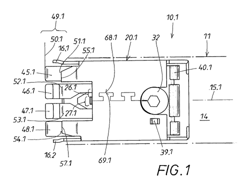
The fastener 10.1 comprises of two parts, namely out of the sheet metal blank
60.1 viewable in figure 14 and of the plate 40.1 visible in figure 9 the sheet
metal
blank 60.1 is formed as a single piece and is formed to a case 20.1 by bending
at the
edges 22.1, 23.1, 24.1, 25.1 as can be recognized in figure 13.
The sheet metal blank 60.1 has specially formed edges 68.1 at the sheet metal
ends 26.1, 27.1 for providing better support after the bending, wherein the
specially
formed edges 68.1 can be brought into working connection with the
corresponding
counter pieces 69.1 for the better support after the bending, in order to
maintain the
sheet metal blank form matching and/or force matching after the bending.
AMENDED SHEET
Dieter Hackenberg PCT/EP2008/003682
CA 02690465 2009-12-10
The end flaps 64.1, 65.1, 66.1 are furnished, which are bent in opposite
directions, in order to limit the freedom of motion of the plate 40.1 in the
sheet metal
blank 60.1. On the oppositely disposed side, the freedom of motion of the
plate 40.1
is limited by the canting 78.1.
Such a mounted fastener 10.1 is shown in figure 1. Sensibly this fastener 10.1
is inserted into a profile 11 in order to hold this profile 11 in the
following by way of
the fastener 10.1 at a counter profile 12. For this purpose the plate 40.1 is
supported
movably in the case 20.1 formed out of the sheet metal blank 60.1 and the
plate 40.1
can be shifted in the longitudinal direction 15.1 of the case.
The case 20.1 has canted off case noses 16.1, 16.2, for better guiding the
fastener 10.1 at a counter profile 12, wherein the case noses 16.1, 16.2 are
applied at
the same outer end 49.1 of the case 20.1, wherein also the hooks 45.1, 46.1,
47.1,
48.1 of the plate 40.1 are applied at the case 20.1. These hooks are arranged
in an
opposite sense in order to be able to grip firmly into a corresponding counter
profile
12 and then to attach the fastener 10.1 in the receiver of 14 of the profile
11 with the
profile 11 at a corresponding counter profile 12. The hooks 45.1, 46.1, 47.1,
48.1
here grip into an undercut groove 13 at the counter profile 12.
During the pulling tight process illustrated in figure 4, the bolt head 32 of
the
eccentric bolt 30 is rotated. The plate 40.1 of the fastener 10.1 is shifted
in
Dieter Hackenberg PCT/EP2008/003682 AMENDED SHEET
CA 02690465 2009-12-10
longitudinal direction based on the cam disk 31 seated under the bolt head 32
such
that the hooks 45.1, 46.1, 47.1, 48.1 pull in the counter profile 12 to the
profile 11.
The path of the cam disk 31 is limited by an inner projection 39.1 at the
fastener 10.1
such that the bolt head 32 cannot be rotated continuously. The case 20.1 has
canted
off bevel faces 51.1, 52.1, 53.1, 54.1, which, upon cooperation with the
tongues 41.1,
42.1, 43.1, 44.1 of the plate 40.1, spread the hooks disposed at the ends of
these
tongues in order to supportingly spread the hooks 45.1, 46.1, 47.1, 48.1
during the
longitudinal motion to for aiding the hooking into the counter profile 12.
This co-
operation of the bevel faces 51.1, 52.1, 53.1, 54.1 with the tongues
41.1,42.1,43.1,
44.1 occurs through the corresponding contact points 55.1, 56.1, 57.1.
Figure 2 and figure 5 illustrate again what is shown in figure 1 and figure 4
as
seen from the opposite side. The journal 34 of the eccentric bolt 30 is
visible in this
view, which eccentric bolt 30 transfers the fastener 10.1 from the open
position of
figure 1 or, respectively, figure 2 into the closed position of figure 4 or,
respectively,
figure 5 through the rotary actuation 33. The pullout position 50.1 and the
plug in
position 50.2 are also here again clearly shown.
Figures 3 and 6 clarify the plug in position 50.2 or, respectively, the
pullout
position 50.1 again in a side view. It can be additionally recognized here
that a
spring loading 70.1 cross to the profile 1 1 is built up during tight pulling
of the
AMENDED SHEET
Dieter Hackenberg PCT/EP2008/003682
CA 02690465 2009-12-10
fastener to the eccentric bolt 30, which spring loading 70.1 holds the
fastener in the
profile 11.
The plate 40.1 is separately considered from the case 20.1 and this in side,
front and perspective views. A leaf spring 28.1 can be recognized in addition
to the
tongues 41.1, 42.1, 43.1, 44.1, which leaf spring serves to enable the above-
mentioned cross force 70.1 to the profile 11 upon pulling tight the fastener
10.1. The
plate inner section 73.1 can be clearly seen in addition in these three
figures, which
plate inner section 73.1 is disposed at the opposite end of the outer end
49.1.
The case 20.1 shows individually in three views of figures 10, 11, and 12 and
this time the case 20.1 in the figures 10, 11 and 12 is shown in the same way
as with
the figure 7, 8, and 9. These three views allow an insight also into the
interior case
21.1 of the case 20.1. The edges 68.1, 69.1 gripping into each other are
presented
here again, which edges are presented here as a widened head 71.1 or,
respectively,
as a narrowed neck 72.1.
The broad sides 35.1, 36.1 and the associated narrow sides 37.1, 38.1
generated after the canting of the sheet metal blank 60.1 are also clearly
shown hei-e
with additional reference to figure 13 and figure 14. The plate 40.1 with the
plate
inner section 73.1 and the plate cutout 29.1 is then laid into this case 20.1,
wherein
the hooks 45.1, 46.1, 47.1, 48.1 are disposed at the plate cut out 29.1.
Additionally,
AMENDED SHEET
Dieter Hackenberg PCT/EP'2008/003682
CA 02690465 2009-12-10
it can be recognized in figure 13 that an expansion of the narrow sides 37,1,
38.1 in
the direction of the forces 50 (translator's remark : should be 58), 59 is
prevented
during hard turning of the eccentric bolt 30.
The free cut 61.1, 62.1, 63.1, and 80.1 caused by the production conditions
can be recognized in figure 14 additionally to the end flaps 64.1, 65.1, 66.1.
An
actuator 75 can be furnished at the bolt head 32 in order to be able to unbolt
again
easier the fastener 10. 1, wherein the actuator 75 transfers the fastener 10.1
by
pressing into the unbolted position. The case 20.1 of the fastener 10.1 at its
front
case end 76.1 can therewith be easier separated from the counter profile 12.
The case
20.1 itself can then completely be taken out of the profile 11 including the
rear case
end 70.1.
Figures 15 through 18 show another embodiment of the fastener 10.1, wherein
the case 20.2 is formed somewhat narrower as compared with the preceding
figures.
The case 20.2 can be recognized with its sheet metal blank 60.2 in figure 18.
All
elements of the sheet metal blank 60.2 can here also again be recognized, such
as the
end flaps 64.2, 65.2, the production caused free cuts 61.2, 62.2, 63.2 and the
noses
16.2, 17.2 of the case 20.2. The case 20.2 with its interior 21.2 of the case
20.2
shown in figure 17 is generated by bending the sheet metal blank 60.2 at the
edges
22.2, 23.2, 24.2, 25.2. The end flaps 64.2, 65.2 are here also beveled in
order to
Dieter Hackenberg PCT/EP2008/003682 AMENDED SHEET
CA 02690465 2009-12-10
! Z~
cooperate with their end regions 26.2, 27.2 with the plate 40.2 laid into the
case 20.2.
The broad sides 35.2, 36.2 as well as the narrow sides 37.2, 38.2 result then
also
again by bending.
The corresponding plate 40.2 contains also two tongues 41.2, 42.2 with the
corresponding hooks 45.2, 46.2 at the outer end 49.2 of the plate 40.2. The
plate
40.2 has furthermore the bevels 51.2, 52.2, which bevels exert the already
mentioned
spreading effect through the contact positions 55.2, 56.2 and the end flaps
64.2, 65.2
of the case 20.2.
The case is again held together by the two edges 68.2, 69.2, which edges 68.2,
69.2 enter into operating connection with a shape matching through broadened
heads
71.2 and narrowed necks 72.2 as shown in figure 17.
The case 20.2 includes again a front case end 76.2 and a
rear case end 77.2, wherein cantings 78.2 are furnished at the rear case end
77.2 for
limiting the motion of the plate 40.2 in the case 20.2.
Finally, figure 19 shows that the canting 78.3 at the rear case end 77.2 can
be
angled by also 90 degrees and can be held with a second canting 79.
A modified embodiment form of the embodiment form shown alT-eady in the
figures 15 through 18 is shown in the drawings to the last embodiment example
Dieter Hackenberg PCT/EP2008/003682 AMENDED SHEET
CA 02690465 2009-12-10
(figure 20 through figure 27). In the shown embodiment example (figure 20
through
figure 27) however the complete fastener is shown and not only the case shown
in
figui-es 15 through 17, but also the profiled plate furnished for the interior
of the case.
An analogous plate 40.1, however with four hooks 45.1 through 48.1, is shown
in the
first embodiment example and in fact in the demounted state in the therewith
associated figures 7 through 9. As can be best recognized from figure 23, the
fastener 10.1 is composed of three components, namely a single part case 20.2
forming a housing, a profiled plate 40.2 disposed in the interior 21.2 of the
case, and
an eccentric bolt 30 rotary supported in the case. According to figure 26, the
initial
section of plate 40.2 is subdivided into two tongues 41, 42, wherein a plate
cut out
29.2 is disposed between the tongues 41, 42 and wherein the plate cut out 29.2
can be
taken from the analogous figure 9. This plate cut out 29.2 serves for forming
a
canted running leaf spring 28.2 in an analogous way as shown in figure 9. In
each
case, a hook 45.2, 46.2 is disposed at the outer free end region of the two
tongues
41.2, 42.2, which hooks 45.2, 46.2 are cranked in an opposite sense to each
other and
project in the assembled case out of the case 40.2 (translator's remark:
should be 20.2)
according to figure 20.
In a use situation discussed in a 10.1 with its case 40.2 (translator's
remark:
should be 20.2) is mounted in the receiver of a profile not shown in detail.
The
eccentric bolt 30 cooperates with this assembly. The eccentric bolt 30 is
furnished
AtViENDED SHEET
Dieter Hackenberg PCT/EP2008/003682
CA 02690465 2009-12-10
with a cam disk 31 disposed in the interior 21.1 of the case and with a bolt
head 32
projecting from the case 20.2. A rotary stop 85 and the journal 34 follow to
the cam
disk 31 in the interior 21.2 of the case, wherein the journal is here rotary
supported in
a particular way to be described in the following in more detail in a rear
case wall
36.2, which case wall 36.2 is generated by the broad sides of the case 20.2.
The bolt
head 32 has a plug receiver 83 recognizable from figure 23 for a plug tool on
the
view side, wherein in the use case a rotary actuation 33 of the eccentric bolt
30
indicated in figure 23 can be performed with the plug tool. All this has the
following
effect.
According to figure 26 the eccentric bolt 30 passes through a breakout 89 in
the inner section 73.2 of the plate 20.2 (translator's remark: should be
40.2). The
cam disk 31 is supported face wise at the inner section 73.2. The already
mentioned
leaf spring 28.2 is seated at the plate inner section 73.2, wherein the leaf
spring 28.2
is supported at its free end 82 at the inner face 81 of the rear case wall
36.2 in an
operational situation of figure 7. The rear case wall 36.2 is subjected to
spring
tension and generates a spring loading in the sense of the force arrow 84 of
figure 7
onto the bolt head 32. The bolt head 22 snaps into a correspondingly
dimensioned
profile opening after the previously recited mounting in the profile receiver.
The
spring loading 84 can be designated as a "cross force" relative to the
longitudinal
shifting direction 86. The bolt head 32 operates like a "pressure button"
based on
AMENDED SHEET
Dieter Hackenberg PCT/EP2008/003682
CA 02690465 2009-12-10
this cross force 84. The bolt head 32 has to be pressed backward into the
interior of
the case like a pressure button in a counter direction to the cross force 84
for the
mounting the fastener 10.1, until the bolt head 32 of the fastener 10.1 has
released the
profile opening. Then the fastener 10.1 can be pulled out of the profile
receiver.
The fastener 10.1 protrudes with its outer end marked with 49.2 in figure 20
out of the profile in the incorporated state of the fastener 10.1 in order to
therewith be
plugged in into an undercut groove of a counter profile not shown in detail.
In
addition to the two hooks 45.2, 46.2 also two case noses 16.1, 16.2 disposed
in the
region of the outer end 49.2 function here as insertion plug parts. The case
noses
16.1, 16.2 are cranked to each other in a mirror image wherein one case nose
is
generated by extension of the case narrow wall 37.2 and the other case nose
16.2 is
generated by a corresponding extension of the oppositely disposed case narrow
wall
38.2 as seen in figures 20 and 24.
The mounted fastener 10.1 should take of a holding together between the
profile and the counter profile, which holding together is accomplished by a
combined spreading and plug in motion of the two end side hooks 45.2, 46.2.
The
longitudinal shifting 86 of the plate 40.2 shown in figures 26 and 27 is a
trigger
therefore. This occurs by the previously mentioned rotary actuation 33 or the
eccentric bolt 30. A pullout position 50.1 of the plate 40.2 is marked by an
auxiliary
AMENDED SHEET
Dieter Hackenberg PCT/EP2008/003682
CA 02690465 2009-12-10
'-~
line in figure 26. In this case the two in mirror image to each other running
hooks
45.2, 46.2 are aligned with the case noses 16.1, 16.2. This can also be
recognized
from figures 21 and 24. The fastener 10. 1 mounted in the profile can be
plugged into
or pulled out of the groove of the counter profile in the pullout position.
The cam
disk 3 1 rests with its circumference on an inner and on an outer carrier
shoulder 87,
88 of the plate 40.2. The carrier shoulders 87, 88 are turned toward the
recited plate
breakout 89 as illustrated in figure 27. While the outer carrier shoulder 88
is
generated by a dent in the plate profile, the inner carrier shoulder is formed
by the
free leg edge of a backward folded loop 91.
The eccentricity of the cam disk moves the plate 40.2 inwardly through the
recited rotary actuation 33. Thus, the recited longitudinal shifting 86
occurs. The
plug in position 50.2 of the plate 40.2 is accomplished after the longitudinal
shifting
86 as illustrated by the further auxiliary line in figure 27. Here a spreading
of the
two hooks 45.2, 46.2 occurs, wherein the two hooks 45.2, 46.2 are moved cross
behind the recited undercut groove wall in the counter profile. This way the
holding
together between the profile and the counter profile are generated through the
fastener 10.1.
The spreading of the hook occurs in the course of the longitudinal shifting 86
and is a performed by an interaction between the plate 40.2 and the case 20.2.
The
AMENDED SHEET
Dieter Hackenberg PCT/EP2008/003682
CA 02690465 2009-12-10
,;.
two tongues 41.2, 42.2 have two bevels 51.2, 52.2 running relative to each
other in
an opposite sense in the front plate region, wherein the two bevels 51.2, 52.2
springingly support themselves in each case at one of two end flaps 64.3, 65.3
as can
be recognized from figures 20 and 23. The contact points 55.2, 56.2
recognizable
from figures 20 and 23 of the tongue bevels 51.2, 52.2 occur at the edges of
the end
flaps 64.3, 65.3. The previously mentioned spreading of the hooks occurs
during the
longitudinal shifting 65, since the contact points 55.2, 56.2 slide along the
bevels
51.2, 52.2 having an opposite sense relative to each other.
The case 20.2 is generated by a multiple bending of a sheet metal blank,
wherein the sheet metal blank preferably consists of steel. This way the
corner
regions of the case 40.2 (translator's remark: should be 20.2) exhibit a
rectangular
profile. Abutting sheet metal ends are generated in the sheet metal cutouts
through
this rectangle folding. The two sheet metal ends 26.2, 27.2 form the front
case broad
wall 35.2 recognizable in figure 23 and have two complementary relative to
each
other running edges 68.2, 69.2 with an undercut edge profile in the region of
the wall
middle. A shape matching of the front case broad wall 35.2 occurs. The single
piece
rectangular shaped closed case 20.2 is generated in this way.
In each case a shoulder 78.2 is generated in extension of the two case narrow
walls 37.2, 38.2 according to figures 21 and 24. The two shoulders 78.2 are
angled
AMENDED SHEET
Dieter Hackenberg PCT/EP2008/003682
CA 02690465 2009-12-10
off relative to each other and point with their shoulder ends toward each
other as is
shown in figure 23. These shoulders 78.2 are in each case furnished with a
formed
on tappet 92, wherein the tappet 92 engages in each case in a hole 93 of the
neighboring case broad wall 36.2 as shown in figure 20. The angle position of
the
two shoulders 78.2 is thereby stabilized.
These shoulders 78.2 perform a support function in the plug in position 50.2
as
seen in figure 27. The plate 40.2 with the end piece of its inner section 73.2
supports
itself at the upper edge of the angled shoulder 78.2 in the plug in position
50.2. The
press in motion of the eccentric bolt into the interior 21.2 of the case is
blocked, since
the eccentric bolt 30 with its cam disk 31 rests at the inner section 73.2.
The bolt
head 32 cannot be pressed in the recited counter direction to its spring
loading 84 of
figure 26 into the plug in position 15.2 (translator's remark: should be 50.2)
of figure
27. The recited push button effect of the bolt head 32 is set to be
ineffective. The
fastener 10.1 is thereby secured in its mounted position in the profile. The
holding
together of profile and counter profile through the fastener 10.1 is also
thereby
completed.
One starting position 82.1 of the free leaf spring end 28.2 is marked by a
first
auxiliary line in figures 26 and 27. This characterizes the position of the
leaf spring
28.2 in the plug in position 50.1. Also the position of the free spring end 82
is
AMENDED SHEET
Dieter Hackenberg PCT/EP2008/003682
CA 02690465 2009-12-10
changed during the plate longitudinal shifting 86 as shown in figure 27 and
comes to
rest in the end position marked with the second auxiliary line 82.2. The
spring end
82 slides over the support face region between the two positions 82.1, 82.2
and
characterized with 94 in figure 27 during the longitudinal shifting 86. A ramp
95 is
disposed in at least one part piece of this support face region 94 according
to the
invention, wherein the ramp rises in the direction of the end position 82.2.
This ramp 95 is generated by a dent 90 in the case broad wall 35.2 in the
present case. The dent 90 projects into the interior 21.2 of the case and
generates the
desired ramp 95 with its front flank. The free spring end 82 is disposed still
at a
distance to the ramp 95 according to figure 26, wherein the starting position
82.1 of
the leaf spring 28.2 is present. These changes however in the end position
82.2 of
figure 27. A contact point 96 results based on the interaction between the
inclined
running leaf spring 28.2 and the ramp 95, wherein a longitudinally directed
longitudinal force 97 effective in the pullout sense is generated on the plate
40.2 at
the contact point 96. The free spring end 82 has lifted off from the inner
face 81 of
the case broad wall 36.2 because of the ramp 96 (translator's remark: should
be 95),
wherein a higher spring force prevails in figure 27 as compared with the
pullout
position 50.1 in figure 26. The spring end 82 assumes a deeper lying contact
position
outside of the dent 90 at the wall inner face 81 in the pullout position 50.1
where as
mentioned the starting position 82.1 is present.
AMENDED SHEET
Dieter Hackenberg PCT/EP2008/003682
CA 02690465 2009-12-10
The previously mentioned longitudinal force 97 becomes effective in the
return rotary motion of the bolt head 32 having an opposite sense relative to
the
rotary motion 33 of figure 23, where the plate 40.2 moves out of its plug in
position
50.2 of figure 27 in the direction of the pullout position 50.1 of figure 26.
A friction
is generated at the contact points 55.2, 56.2 between the end flaps 64.3 or,
respectively, 65.3 and the tongue bevels 51.2 or, respectively, 52.2, which
friction
impedes the outward motion and the folding together motion of the associated
two
hooks 45.2, 46.2. The previously mentioned longitudinal force 97 between the
ramp
95 and the leaf spring 28.2 favors this outward motion. The actuation of the
eccentric bolt 30 occurs easily according to the invention.
The case wall 36.2 exhibiting already the ramp generating dent 90, is
furnished
with an impression which shows a central breakout 99. A funnel structure is
generated in the case wall 36.2 based on the impression 98, wherein the funnel
structure receives and rotary guides the inner end of the journal 34 of the
eccentric
bolt 30.
The side case walls 37.2, 38.2 are furnished with notches 100 as shown in
figures 21 and 24, wherein the notches 100 direct into the interior of the
housing.
One of the notches can also be r-ecognized in figure 26. Each notch 100 has an
apex
region 101, wherein oppositely disposed narrow sides of the plate 20.2 in the
case
Dieter Hackenberg PCT/EP2008/003682 AMENDED SHEET
CA 02690465 2009-12-10
interior 21.2 support themselves at the apex region 101. A plate guidance is
performed both in the rest position as well as also during the recited
longitudinal
shifting 86 through this contacting in the apex region 101. This point wise
touching
decreases also the friction resistance during the longitudinal shifting 86.
The fastener
10.1 according to the invention is easily moving in its rotary actuation 33
also for
that reason.
AMEINDED SHEET
Dieter Hackenberg PCT/EP2008/003682
CA 02690465 2009-12-10
List of reference characters
10.1 fastener
11 profile
12 counter profile
13 undercut groove at 12
14 seat in 11
15.1 case longitudinal direction of 20.1
16.1 first case nose
16.2 first case nose
17.1 second case nose
17.2 second case nose
20.1 first case
20.2 second case
20.3 third case
21.1 interior of the case 20.1
21.2 interior of the case 20.2 22.1 first folding of 20.1
22.2 first folding of 20.2
23.1 second folding of 20.1
23.2 second folding of 20.2
AMENDED SHEET
Dieter Hackenberg PCT/EP2008/003682
CA 02690465 2009-12-10
4. ~
24.1 third folding of 20.1
24.2 third folding of 20.2
25.1 fourth folding of 20.1
25.2 fourth folding of 20.2
26.1 first sheet metal end of 20.1, border profile
26.2 first sheet metal end of 20.2, border profile
27.1 second sheet metal end of 20.1, border profile
27.2 second sheet metal and of 20.2, border profile
28.1 leaf spring of 40.1 for 70.1 (figure 7)
28.2 leaf spring at 40.2 (figures 26, 27)
29.1 plate cut out in 40.1 (figure 9)
29.2 plate cut out between 41.2, 42.2 (figure 26)
30 eccentric bolt
31 cam disk of 30
32 bolt head of 30 (figures 1, 23, 27)
33 rotary actuation of 30 (figures 4, 23)
34 journal of 30
35.1 first broad side of 20.1
35.2 first broad side of 20.2
36.1 second broad side of 20.1
AMENDED SHEE~'
Dieter Hackenberg PCT/EP2008/003682
CA 02690465 2009-12-10
, -~
36.2 second broad side of 20.2
36.3 second broad side of 20.3 (figure 19)
37.1 first narrow side of 20.1
37.2 first narrow side of 20.2
37.3 first narrow side of 20.3 (figure 19)
38.1 second narrow side of 20.1
38.2 second narrow side of 20.2
38.3 second narrow side of 20.3 (figure 19)
39.1 inner projection, rotary stop (figures 1, 4)
40.1 plate for 10.1
40.2 plate (figures 26, 27)
41.1 first tongue of 40.1
41.2 first tongue of 40.2
42.1 second tongue of 40.1
42.2 second tongue of 40.2
43.1 third tongue of 40.1
44.1 fourth tongue of 40.1
45.1 first hook at 41.1
45.2 first hook at 41.2
46.1 second hook at 42.1
AMENDED SHEET
Dieter Hackenberg PCT/EP2008/003682
CA 02690465 2009-12-10
_.C
46.2 second hook at 42.2
47.1 third hook at 43.1
48.1 fourth hook at 44.1
49.1 outer end of 40.1
49.2 outer end at 10.2 (translator's remark: should be 40.2)
50.1 pullout position of 40.1
50.2 plug in position of 40.1
51.1 first bevel at 41.1
51.2 bevel at 41.2
52.1 second bevel at 42.1
52.2 bevel at 42.2
53.1 third bevel at 43.1
54.1 fourth bevel at 44.1
55.1 first contact point for 51.1
55.2 first contact point
56.1 second contact point for 52.1
56.2 second contact point
57.1 third contact point for 54.1
58 stretching force (figure 13)
59 stretching counter force (figure 13)
AMENDED SHEET
Dieter Hackenberg PCT/EP2008/003682
CA 02690465 2009-12-10
60.1 sheet metal blank for 20.1 (figure 14)
60.2 sheet metal blank for 20.2 (figure 18)
61.1 first free cut in 60.1
61.2 first free cut in 60.2
62.1 second free cut in 60.1
62.2 second free cut in 60.1 (translator's remark: should be 60.2)
63.1 third free cut in 60.1
63.2 third free cut in 60.1 (translator's remark: should be 60.2)
64.1 first end flap at 20.1
64.2 first end flap at 20.2
64.3 end flap at 35.2 (figure 23)
65.1 second end flap at 20.1
65.2 second end flap at 20.2
65.3 end flap at 36.2 (figure 20)
66.1 third end flap at 20.1
68.1 first edge of 26.1, contour profile (figure 14)
68.2 first edge of 26.2, contour profile (figure 18)
69.1 second edge at 27.1, contour profile (figure 14)
69.2 second edge at 27.2, contour profile (figure 18)
70.1 spring loading of 73/30 (figure 3) AMENDED SHEET
Dieter Hackenberg PCT/EP2008/003682
CA 02690465 2009-12-10
71.1 widened head at 68.1 or 69.1
71.2 widened head at 68.2 or 69.2
72.1 narrowed neck of 68.1 or 69.1
72.2 narrowed neck of 68.2 or 69.2
73.1 plate inner section of 40.1
73.2 inner section of 20.2 (figures 26, 27)
75 pushbutton press in actuation of 32
76.1 front case end of 20.1
76.2 front case end of 20.2
77.1 rear case end of 20.1
77.2 rear case end of 20.2
78.1 angling off for support at 37.1 and 38.1
78.2 angling off for support at 37.2 and 38.2
78.3 angling off of 37.3, 38.3 (figure 19)
79 second angling off for support at 36.3 (figure 19)
80.1 fourth free cut (figure 14)
81 wall inner face of 36.2 (figures 26, 27)
82 free end of 28.2 (figures 26, 27)
82.1 starting position of 82 (figures 26, 27)
82.2 end position of 82 (figure 27)
AMENDED SHEET
Dieter Hackenberg PCT/EP2008/003682
CA 02690465 2009-12-10
83 plug receiver in 32 (figure 23)
84 force arrow of the spring loading of 32, cross force to 86 (figure 26)
85 rotary limit stop at 30 (figures 24, 27)
86 arrow of the longitudinal shifting of 40.2 (figures 26, 27)
87 inner carrier shoulder between 40.2, 31 (figure 26)
88 outer carrier shoulder between 40.2, 31 (figure 26)
89 plate breakout in 40.2 for 30 (figure 27)
90 dent in 36.2 (figures 26, 27)
91 end side loop for 87 (figures 23, 27)
92 tappet at 78.2 (figures 20, 21, 24)
93 hole for 92 in 36.2 (figure 20)
94 region of the support face for 82 (figure 27)
95 ramp in 94 for 28.2 (figures 26, 27)
96 contact point between 28.2, 95 (figure 27)
97 longitudinal force acting in the pullout sense of 40.2 (figure 27)
98 impression in 36.2 for 34, funnel structure (figures 20, 27)
99 central hole in 98
100 notch in 37.2, 38.2 (figures 21, 24, 26)
101 apex region of 100 (figures 21, 24)
AMENDED SHEET
Dieter Hackenberg PCT/EP2008/003682