Sélection de la langue

Search

Sommaire du brevet 2690528 

Énoncé de désistement de responsabilité concernant l'information provenant de tiers

Une partie des informations de ce site Web a été fournie par des sources externes. Le gouvernement du Canada n'assume aucune responsabilité concernant la précision, l'actualité ou la fiabilité des informations fournies par les sources externes. Les utilisateurs qui désirent employer cette information devraient consulter directement la source des informations. Le contenu fourni par les sources externes n'est pas assujetti aux exigences sur les langues officielles, la protection des renseignements personnels et l'accessibilité.

Disponibilité de l'Abrégé et des Revendications

L'apparition de différences dans le texte et l'image des Revendications et de l'Abrégé dépend du moment auquel le document est publié. Les textes des Revendications et de l'Abrégé sont affichés :

  • lorsque la demande peut être examinée par le public;
  • lorsque le brevet est émis (délivrance).
(12) Brevet: (11) CA 2690528
(54) Titre français: SUPPORT MOBILE SERVANT A FIXER UN DISPOSITIF ANTICHUTE
(54) Titre anglais: MOBILE MOUNT FOR ATTACHMENT OF A FALL ARREST SYSTEM
Statut: Réputé périmé
Données bibliographiques
(51) Classification internationale des brevets (CIB):
  • A62B 99/00 (2009.01)
  • A62B 1/00 (2006.01)
  • A62B 35/00 (2006.01)
  • E06C 5/32 (2006.01)
  • E06C 7/18 (2006.01)
(72) Inventeurs :
  • VETESNIK, JAN (Canada)
(73) Titulaires :
  • D B INDUSTRIES, LLC (Etats-Unis d'Amérique)
(71) Demandeurs :
  • CAPITAL SAFETY GROUP WINNIPEG LTD. (Canada)
(74) Agent: CASSAN MACLEAN IP AGENCY INC.
(74) Co-agent:
(45) Délivré: 2012-10-02
(22) Date de dépôt: 2004-05-07
(41) Mise à la disponibilité du public: 2005-11-07
Requête d'examen: 2010-01-20
Licence disponible: S.O.
(25) Langue des documents déposés: Anglais

Traité de coopération en matière de brevets (PCT): Non

(30) Données de priorité de la demande: S.O.

Abrégés

Abrégé français

Un support mobile servant de fixation d'un dispositif antichute, utilisé avec les avions par exemple. Le support comprend une base reposant sur des roues, un support réglable en hauteur capable de s'élever à partir de la base et une passerelle en porte-à-faux au-dessus de la base. Au moins un dispositif de fixation est monté sur le bras du support à une position située au-dessus de la base; ce dispositif permet de fixer un système antichute, y compris un harnais pour une ou plusieurs personnes. Le dispositif de fixation, la base et le support sont conçus et disposés de manière à avoir une capacité de charge suffisante pour encaisser le poids d'une personne qui tomberait de la structure surélevée.


Abrégé anglais

A mobile mount for attachment of a fall arrest system is provided for example for aircraft and includes a base carried on ground wheels and a support which is adjustable in height upstanding from the base and an arm cantilevered over the base. At least one receptacle is mounted on the arm of the support at a position located over the base for attachment to a personal fall arrest system including a harness for one or more persons, with the receptacle, base and support being designed and arranged to receive a loading from the personal fall arrest system sufficient to accommodate a fall of the person from the elevated structure.

Revendications

Note : Les revendications sont présentées dans la langue officielle dans laquelle elles ont été soumises.


12

What is claimed is:


1. Apparatus comprising:

a base carried on ground wheels for movement over a ground surface to an
elevated structure on which one or more persons is intended to work;

a ladder upstanding from the base to an elevated position above the base;
the upstanding ladder being adjustable in height from the base;

the upstanding ladder including two side rails and transverse rungs such
that said one or more persons can climb the ladder to the elevated structure;

at least one of the side rails of the ladder having mounted thereon a tubular
receptacle;

a post member mounted in the tubular receptacle and shaped and arranged
so as to extend upwardly from the receptacle and forwardly beyond the end of
the
upper part of the ladder;

and at least one support member at an end of the post member remote from
the tubular receptacle for attachment to and loading from a personal fall
arrest
system for attachment to said one or more persons.


2. The apparatus according to Claim 1 wherein each of the side rails includes
a respective tubular receptacle and a respective post member and wherein there

are at least two support members each carried on a respective one of the post
members and each for receiving the personal fall arrest system of a respective
one
of two separate persons.


13


3. The apparatus according to Claim 1 or 2 wherein the at least one support
member is mounted so as to allow side to side movement of the support member
relative to the base.


4. The apparatus according to Claim 1, 2 or 3 wherein the base includes a
hitch by which the base can be moved to the elevated structure by a towing
vehicle.


5. The apparatus according to any one of Claims 1 to 4 wherein there is
provided a platform at a top of the ladder extending from the top of the
ladder
outwardly over the base.


6. The apparatus according to any one of Claims 1 to 5 wherein the post
member and the support member are arranged such that the support member is
cantilevered generally over a mid line of the base.


7. The apparatus according to any one of Claims 1 to 6 wherein at least one
support member comprises a loop for receiving a hook of the personal fall
arrest
system.


8. The apparatus according to any one of Claims 1 to 7 wherein the post
member is inclined forwardly of an upper end of the side rail to cantilever
the
support member in front of the ladder.


9. The apparatus according to any one of Claims 1 to 8 wherein the platform
between rails at the top of the ladder is for the person to step onto the
elevated
structure.


14


10. The apparatus according to any one of Claims 1 to 9 wherein the tubular
receptacle allows adjustment of the post member relative to the side rail of
the
ladder.


11. The apparatus according to any one of Claims 1 to 10 wherein the tubular
receptacle allows height adjustment of the post member relative to the side
rail of
the ladder.

Description

Note : Les descriptions sont présentées dans la langue officielle dans laquelle elles ont été soumises.


CA 02690528 2010-01-20

MOBILE MOUNT FOR ATTACHMENT OF A FALL ARREST SYSTEM

The present invention relates to a mobile mount for attachment of a fall
arrest system.

BACKGROUND OF THE INVENTION

Full protection of operators working in a situation where a fall can take
place over a sufficient distance to cause injury or death is becoming
generally
required in most industries. Many arrangements are provided for mounting an
anchor post on a structure adjacent the worker so that a personal fall arrest
system
can be attached to the anchor.

Such personal fall arrests systems include a harness together with a
cable system for attachment to the harness and to a suitable anchor where the
cable
system can be paid out to allow the worker to move to a required location but
the
cable system arrests any fall within a short distance. Such devices are well
known
and commercially available and many different designs have been proposed.

In most cases the structure itself provides or has attached a suitable
anchoring post so that the relatively high loading necessary can be readily
provided
by a simple post rigidly attached to the structure.

In the interior buildings, such anchors can be mounted on a rail which
allows the anchor to slide longitudinally along a track attached to the rail.

However some structures are unsuitable for attachment of an anchor
post or have been designed without the possibility of attachment of an anchor
post
so that operators in this environment are often unprotected against fall. In a
particular area where this is problematic is in that related to aircraft where
aircraft


CA 02690528 2010-01-20

2
design does not lead to the suitability of attachment of mounting posts. Up
until
now, therefore, operators working in this environment have remained
unprotected
with the potential of serious injury or death.

SUMMARY OF THE INVENTION

According to one aspect of the invention, there is provided an
apparatus which includes a base carried on ground wheels for movement over a
ground surface to an elevated structure on which one or more persons is
intended to
work. A ladder is upstanding from the base to an elevated position above the
base.
The upstanding ladder is adjustable in height from the base. The upstanding
ladder

includes two side rails and transverse rungs such that said one or more
persons can
climb the ladder to the elevated structure. At least one of the side rails of
the ladder
has mounted thereon a tubular receptacle. A post member is mounted in the
tubular receptacle and shaped and arranged so as to extend upwardly from the
receptacle and forwardly beyond the end of the upper part of the ladder. At
least

one support member at an end of the post member remote from the tubular
receptacle for attachment to and loading from a personal fall arrest system
for
attachment to said one or more persons.

Preferably, each of the side rails includes a respective tubular
receptacle and a respective post member where there are at least two support
members each carried on a respective one of the post members and each for

receiving the personal fall arrest system of a respective one of two separate
persons.


CA 02690528 2010-01-20

3
Preferably the at least one support member is mounted so as to allow
side to side movement of the support member relative to the base.

Preferably the base includes a hitch by which the base can be moved
to the elevated structure by a towing vehicle.

Preferably there is provided a platform at a top of the ladder extending
from the top of the ladder outwardly over the base.

Preferably the post member and the support member are arranged
such that the support member is cantilevered generally over a mid line of the
base.
Preferably the or each support member comprises a loop for receiving
a hook of the personal fall arrest system.

Preferably the post member is inclined forwardly of an upper end of the
side rail to cantilever the support member in front of the ladder.

Preferably there is provided a platform between rails at the top of the
ladder for the person to step onto the elevated structure.

Preferably the tubular receptacle allows adjustment of the post
member relative to the side rail of the ladder.

Preferably the tubular receptacle allows height adjustment of the post
member relative to the side rail of the ladder.

BRIEF DESCRIPTION OF THE DRAWINGS

On embodiment of the invention will now be described in conjunction
with the accompanying drawings in which:


CA 02690528 2010-01-20

4
Figure 1 is an isometric view of the first embodiment according to the
present invention.

Figure 2 is an isometric view of the embodiment of Figure 1 modified to
incorporate a ladder and platform by which the operator can raise to the
elevated
structure.

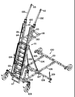
Figure 3 is an isometric view of a second embodiment according to the
present invention.

Figure 4 is an isometric view of a modified version of the embodiment
of Figure 3 incorporating two of the components of Figure 3 connected
together.

DETAILED DESCRIPTION

In Figure 1 is shown a first embodiment according to the present
invention which includes a base 10 and a support 11 for supporting anchors or
receptacles 12 and 13 at a raised position above the base.

The base comprises a pair of side rails 14 and 15 extending forwarding
from a rear frame structure 15. At the outer end of each side rail is provided
a
ground engaging wheel 16 for rolling over the ground supporting the base.

The frame 15 comprises a pair of rails 17 and 18 which are parallel and
generally at right angles to the side rails 14 and 14A. The rails 17 and 18
are
parallel and interconnected by a number of cross members 19 which hold the
rails

parallel. The rails 14 and 14A are attached to respective ends of the rails 17
and 18
so as to form a rigid structure. Some of the cross members 19 extend outwardly
beyond the rails 17 and 18 and provide a support for a ground wheel 20 which
co-


CA 02690528 2012-03-07

operates with a ground wheel 16 in supporting the base for movement across the
ground. The number of ground wheels and arrangement of ground wheels
depends upon the weight to be supported and the type of ground wheel to be
used.
The base provides a relatively wide area for support over the ground to
prevent
5 toppling of the structure when load is applied.

At opposite ends of the frame 15 is provided a pair of upstanding posts
22 and 23 which form a part of the support 11. The upstanding posts are formed
in
two sections including upper portions 22A and 23A which are slidable
vertically
relative to the lower portions 22B and 23B. Suitable mounting using bearings
can

be provided between the portions to allow the vertical sliding movement
required to
elevate the upper section relative to the lower section. A cross member 24
connects the upper end of the lower portions 22B and 23B to retain the
structure
rigid. A similar cross member 25 is provided across the top of the upper
portions
22A and 23A to maintain the upper section rigid. The upper section is raised

relative to the lower section by chains 26 and 26a carried on lower pulleys 27
and 28
respectively operated by manually rotatable handle 29 attached to a shaft 30.
The
shaft 30 extends between the two pulleys 27 and 28 so the rotation of the
handle 29
pulls the chains 26 and 27 over an upper pulley 31, 32 respectively at the top
of the
respective posts portions 22B and 23B so as to pull on the lower end of the
upper

portions 22A and 23A pulling them upwardly along the slide mounting indicated
at
34.


CA 02690528 2010-01-20

6
Thus the upright portion of the support 11 defined by the posts and the
cross members can be raised and lowered to a required height. At the top of
the
upper portion of the posts is provided a cantilever arm section generally
indicated at
35 forming part of the support 11. The cantilever arm structure comprises a
rail 36

parallel to the cross beams 25 and 24 and cantilevered outwardly therefrom on
support rails 37, 38, 39 and 40. The rails 38 and 40 form a brace at an angle
to the
rails 37 and 39 thus maintaining the rail 36 at a position approximately
midway
across the base from the frame 15 towards the wheels 16.

The rail 36 is formed by a structural tube together with a transport track
attached to the underside of the structural tube so the track carries a pair
of trolleys
41 and 42 which can slide along the track 43 independently of one another.
Each
trolley carries a respective one of the anchors 12, 13.

Thus the operator shown in Figure 1 can be wheeled to a required
location at an elevated structure with the rail 36 supported at a position
above the
elevated structure by any necessary adjustment of the height of the support.
The

location of the rail 36 over the elevated structure can be obtained by moving
the
base on the wheels to the required position relative to the elevated
structure. The
arrangement as shown is particularly suitable for location over the wing of an
aircraft
with the rail 36 at a position approximately head height above the operator
standing

on the wing. Thus the base is located under the wing with the rail 36 above
the
wing.


CA 02690528 2010-01-20

7
The structure is designed and arranged to provide sufficient loading so
that the anchors can receive the full force obtained by an operator falling
from the
elevated structure.

In practice it has been determined that the necessary loading which the
anchor must accommodate is of the order of 1800 lbs. for a single operator and
either 2000 lbs. or 3000 lbs. for two operators depending upon the
jurisdiction where
the standards are in force. Thus the anchor is not merely an anchor location
but
must provide sufficient strength so that the fall of a heavy operator
potentially
carrying heavy equipment and the impact of that fall on the personal fall
arrest

system can be applied to the anchor and through the anchor to the ground
without
damaging the structure or allowing the operator to fall beyond the intended
position
arrested by the fall arrest system.

Turning now to Figure 2, there is shown exactly the same structure as
shown in Figure 1 together with the additional elements of a ladder 50, a
platform 51
and a hitch 52. The ladder 50 comprises side rails 53 and 54 together with

transverse rungs 55. The ladder is formed of a lower section 56 and an upper
section
57 which can extend at its lower section 56 by sliding along side rails at a
coupling
58. The upper end of the ladder is mounted on a cross beam 59 attached to the
slides 34 by posts 60. Thus the upper end of the ladder is attached to the
upper part

of the frame for elevation therewith so that elevation of the other part of
the frame
obtained by the operator rotating the handle 29 automatically acts to lift the
upper
end of the ladder relative to the lower end of the ladder. The lower end of
the ladder


CA 02690528 2010-01-20

8
is attached to a pair of extension pieces 62 and 63 which extend outwardly
from
respective ones of the cross members 19 of the frame 15. Such cross members
can be formed from a tube so that the lower part of the ladder includes a
smaller tube
inserted into the outer tube of the cross member 19 for readily attaching the
ladder to
the structure.

Thus the lower end of the ladder is fixed and the upper extends with the
support to the required height to allow the operator to climb the ladder to
the required
location. At the top of the ladder is provided the platform 51 which is
cantilevered
out from the rail 59 and may be supported by braces from the rail 25. The
platform

provides a horizontal surface onto which the operator can step to transfer
from the
ladder to the horizontal surface and from the horizontal surface onto the
structure to
be worked upon. Alternatively the operator may remain on the platform to carry
out
the work while protected from falling by the fall restraint system provided by
the
anchors 12 and 13. Hand rail 51A can supplement the platform to allow the
operator to stand while supported.

Turning now to Figure 3, an alternative embodiment is shown including
a base 100 and a support 111 for anchors 112 and 113. In this embodiment the
base 100 is formed by cross beams 101 and 102 carrying ground wheels 103
together with longitudinal beams 104 and 105. The wheels are suitable castor

wheels or may alternatively be driven wheels for moving the base by powered
operation.


CA 02690528 2010-01-20

9
In this embodiment the support 111 is in the form of a ladder structure
114 with side rails 115 and 116 together with transverse rungs 117 and an
upper
platform 118. The ladder structure is again formed in two pieces with an upper
part
120 which can be raised relative to a lower part 121 by actuation of a
manually

operable chain lifting system 124. Thus the upper parts of the rails of the
ladder can
slide upwardly to raise the platform 118 and the anchors 112 and 113 to a
required
height above an elevated structure to be operated on. The lower part of the
ladder
is rigidly attached to the cross beam 103 and is supported by braces 125 and
126
extending downwardly to the longitudinal rails 104 and 105. The lower end of
the

braces is attached to slide members 127 which can move longitudinally along
the
respective rails 104, 105 and carry a cross beam 128 which has stabilizing
legs 129
at each end. Stabilizing legs can be moved down into engagement with the
ground
so as to transfer some loading from the base from the wheels to the legs to
maintain
the base at a required location.

At the upper end of the rails 115 and 116 of the ladder is provided a
tubular receptacle 130, 131 for a curved post 132 and 133 respectively which
extends upwardly from the receptacle and forwardly beyond the end of the upper
part of the ladder to the upper anchor 112, 113 respectively. Thus the anchors
are
cantilevered forwardly beyond the end of the ladder by the curvature of the
posts 132

and 133. Thus again the anchors 112 and 113 are located approximately over the
midline of the base and a cantilevered over structure with the base located
underneath the structure. Again this arrangement is particularly suitable for
the


CA 02690528 2010-01-20

wing of an aircraft where the base can be moved to a position beneath the wing
with
the platform moved up to the end of the wing and the anchors 112 and 113
located
over the wing for the operator to transfer from the platform onto the wing for
operations on the aircraft.

5 In Figure 4 is shown an alternative arrangement which utilizes basically
the structure of Figure 3 arranged in a pair of such structures connected
together by
cross members 140 and 141. Thus each base 100 and each support 111 is
provided at a position spaced transversely of the base frames and connected
together at spaced positions by the rails 140 and 141. At the top of the post
132 and

10 133 is provided a transverse rail 136 similar to the rail 36 which carries
a track 137
and trolleys 138. Each trolley is attached to a personal safety arrest system
generally indicated at 145. Thus the basic system shown in Figure 3 can be
modified to provide an elongated structure to provide an elongated protection
system along the full extent of the rail 136 which may be up to 30 feet in
length so

that a number of operators can be properly protected by personal fall arrest
systems
slidable along the rail 136 in its track 137. The rail 136 can be removed from
the
posts 132 and 133 and the base 100 can be separated to provide two separate
elements which can be used independently. The base structure in Figure 4 is
slightly different in construction from that shown in Figure 3 in that the
side rails

extend at an angle outwardly and the wheels are attached to the ends of the
side
rails rather than to the ends of the cross rail 101 as shown in Figure 3. It
will be
appreciated that different forms of base structure be designed with the
intention that


CA 02690528 2010-01-20

11
the structure merely provides sufficient ground engagement area to accommodate
any side loads which occur as an operator falls to prevent the system from
toppling
and to maintain the rail 136 at its elevated position despite any direction of
fall of one
or more operators from the elevated structure.

The structure shown in Figure 1 can also be extended by providing
additional posts and increasing the length of the rails 24, 25 and 36. Thus
for
example the basic rail 36 may be of the order of 20 ft. which should be
increased to
30 ft. by providing an additional post to provide three such posts in a row.

Since various modifications can be made in my invention as herein
above described, and many apparently widely different embodiments of same made
within the spirit and scope of the Claims without department from such spirit
and
scope, it is intended that all matter contained in the accompanying
specification shall
be interpreted as illustrative only and not in a limiting sense.

Dessin représentatif
Une figure unique qui représente un dessin illustrant l'invention.
États administratifs

Pour une meilleure compréhension de l'état de la demande ou brevet qui figure sur cette page, la rubrique Mise en garde , et les descriptions de Brevet , États administratifs , Taxes périodiques et Historique des paiements devraient être consultées.

États administratifs

Titre Date
Date de délivrance prévu 2012-10-02
(22) Dépôt 2004-05-07
(41) Mise à la disponibilité du public 2005-11-07
Requête d'examen 2010-01-20
(45) Délivré 2012-10-02
Réputé périmé 2018-05-07

Historique d'abandonnement

Il n'y a pas d'historique d'abandonnement

Historique des paiements

Type de taxes Anniversaire Échéance Montant payé Date payée
Requête d'examen 800,00 $ 2010-01-20
Enregistrement de documents 100,00 $ 2010-01-20
Le dépôt d'une demande de brevet 400,00 $ 2010-01-20
Taxe de maintien en état - Demande - nouvelle loi 2 2006-05-08 100,00 $ 2010-01-20
Taxe de maintien en état - Demande - nouvelle loi 3 2007-05-07 100,00 $ 2010-01-20
Taxe de maintien en état - Demande - nouvelle loi 4 2008-05-07 100,00 $ 2010-01-20
Taxe de maintien en état - Demande - nouvelle loi 5 2009-05-07 200,00 $ 2010-01-20
Taxe de maintien en état - Demande - nouvelle loi 6 2010-05-07 200,00 $ 2010-04-28
Taxe de maintien en état - Demande - nouvelle loi 7 2011-05-09 200,00 $ 2011-05-06
Enregistrement de documents 100,00 $ 2011-06-21
Enregistrement de documents 100,00 $ 2011-08-23
Taxe de maintien en état - Demande - nouvelle loi 8 2012-05-07 200,00 $ 2012-04-04
Taxe finale 300,00 $ 2012-07-23
Enregistrement de documents 100,00 $ 2013-02-01
Taxe de maintien en état - brevet - nouvelle loi 9 2013-05-07 200,00 $ 2013-05-06
Taxe de maintien en état - brevet - nouvelle loi 10 2014-05-07 250,00 $ 2014-03-31
Taxe de maintien en état - brevet - nouvelle loi 11 2015-05-07 250,00 $ 2015-04-02
Taxe de maintien en état - brevet - nouvelle loi 12 2016-05-09 250,00 $ 2016-04-13
Titulaires au dossier

Les titulaires actuels et antérieures au dossier sont affichés en ordre alphabétique.

Titulaires actuels au dossier
D B INDUSTRIES, LLC
Titulaires antérieures au dossier
CAPITAL SAFETY GROUP CANADA LTD.
CAPITAL SAFETY GROUP WINNIPEG LTD.
D B INDUSTRIES, INC.
UNIQUE CONCEPTS LTD.
VETESNIK, JAN
Les propriétaires antérieurs qui ne figurent pas dans la liste des « Propriétaires au dossier » apparaîtront dans d'autres documents au dossier.
Documents

Pour visionner les fichiers sélectionnés, entrer le code reCAPTCHA :


Pour visualiser une image, cliquer sur un lien dans la colonne description du document. Pour télécharger l'image (les images), cliquer l'une ou plusieurs cases à cocher dans la première colonne et ensuite cliquer sur le bouton "Télécharger sélection en format PDF (archive Zip)" ou le bouton "Télécharger sélection (en un fichier PDF fusionné)".

Liste des documents de brevet publiés et non publiés sur la BDBC .

Si vous avez des difficultés à accéder au contenu, veuillez communiquer avec le Centre de services à la clientèle au 1-866-997-1936, ou envoyer un courriel au Centre de service à la clientèle de l'OPIC.


Description du
Document 
Date
(yyyy-mm-dd) 
Nombre de pages   Taille de l'image (Ko) 
Dessins représentatifs 2010-03-12 1 13
Page couverture 2010-03-19 2 48
Abrégé 2010-01-20 1 17
Description 2010-01-20 11 391
Revendications 2010-01-20 3 70
Dessins 2010-01-20 4 130
Dessins représentatifs 2012-01-31 1 13
Description 2012-03-07 11 392
Revendications 2012-03-07 3 70
Dessins 2012-03-07 4 133
Dessins représentatifs 2012-09-12 1 19
Page couverture 2012-09-12 2 52
Correspondance 2010-02-19 1 36
Cession 2010-01-20 17 760
Lettre du bureau 2018-02-05 1 33
Poursuite-Amendment 2010-03-15 1 42
Cession 2011-08-23 5 195
Correspondance 2010-06-09 1 15
Cession 2010-06-14 13 667
Poursuite-Amendment 2010-09-30 1 45
Correspondance 2011-07-13 1 21
Cession 2011-06-21 13 400
Poursuite-Amendment 2012-02-01 2 42
Poursuite-Amendment 2012-03-07 11 316
Correspondance 2012-07-23 1 53
Cession 2013-02-01 14 407