Note : Les descriptions sont présentées dans la langue officielle dans laquelle elles ont été soumises.
CA 02699699 2012-06-05
STABILIZING ASSEMBLY OF DRAWABLE CARRIER
Description
Field of the Invention
The present invention relates to a structural assembly for orienting and
stabilizing
a drawable carrier so as to not only prevent the drawable carrier from sliding
bias and
swinging but also eliminate noise caused by jogging or disengaging gears when
the
drawable carrier is pushed or drawn to slide.
Background of the Invention
Generally, between a cabinet body and a drawer installed therein, there are
drawer slides composed of sliding rails and sliding guides for easy and smooth
slide of
the drawer inward or outward the cabinet body. However, since sliding rails
and sliding
guides are usually assembled with intervals of considerable width
therebetween, when a
pulling or pushing force is exerted on any point of the drawer except the
center of the
facade of the drawer, the drawer slides bias, leading to abnormal operation
and thus
wear of the drawer, eventually reducing the service life of the drawer.
For remedying this problem, the inventor of the present invention proposed an
invention. Therein, in addition to drawer slides that guide a drawable carrier
to slide in
or out a cabinet body, the prior art device, at two laterals of the drawable
carrier, has
row holes (functioning as two lateral racks) or fixed components formed with
row holes
that are aligned along the sliding direction of the drawable carrier, and has
an engaging
assembly that includes a rod having two ends equipped with gears, wherein the
gears
engage with the corresponding row holes on the bottom of the drawable carrier,
and the
rod is supported by two seats fixed to the cabinet body, which seats each has
a spring to
prop up the rod, so that the upward pushing force the springs exert on the rod
ensures
proper engagement between the gears at the two ends of the rod and the row
holes.
By the technical means of the prior art-device, when the drawable carrier is
drawn or
pushed to slide, even if the force exerting point is not right at the center
of the facade of the
drawable carrier, the limitation provided by the mutually engaging gears and
the
1
CA 02699699 2011-04-26
row holes, which ensures the gears to move along the row holes without
derailment,
maintains the sliding direction of the drawable carrier without deviation.
However, when
the drawable carrier, especially in the case where the drawable carrier is a
large drawer,
is drawn or pushed at one of its lateral edge of its facade furthest from the
center and
thus received an extremely transversely unbalanced force, the gears are liable
to escape
from the row holes, causing the drawable carrier to seriously slant to one
side and
become aberrant. Such aberration not only brings about sliding noise, but also
leads to
accelerative wear of the gears and the row holes, or, even forces the two side
gears to
jump out of the row holes, incurring damage to the structural components.
Summary of the Invention
For preventing disengagement and noise between the slide guide and the
drawable
carrier, the present invention provides a retaining device settled between a
cabinet body
and a drawable carrier. The retaining device prevents the drawable carrier
from sliding
bias and causing noise due to jogging or disengaging gears in sliding of the
drawable
carrier.
The technical approach adopted by the present invention for solving the
technical
problems of the prior art device lies on a retaining device arranged between a
cabinet
body and a drawable carrier for guiding slide. The retaining device includes
rails that are
settled between the cabinet body and two laterals of the drawable carrier and
have racks
extending along the sliding direction of the drawable carrier, and a rolling
shaft
composed of a rod, two gears at two ends of the rod for properly engaging with
the racks
without the risk of biasing, wherein two bushes are connected to two ends of
the rod and
fittingly received in two corresponding supporting seats and each said bush is
foi med
with a retained portion near the corresponding gear, and a stop unit on the
rail toward the
rod opposite to the rack on the rail and being closely adjacent to and
separated from the
rod by a predetermined distance.
In addition, the stop unit of the present invention as described above is
materialized
as stop portions each extending from the rail toward a side of the bush
opposite to
2
CA 02699699 2013-03-21
another side of the bush facing the rack on the rail, wherein terminals of the
stop
portions are closely adjacent to the retained portion of the bush.
The present invention is advantageous as it orientates the sliding drawable
carrier
and improves operational noise. Since the inventive device uses engagement
between
the bushes and the rod to orientate the gears on the racks instead of the
springs propping
up the rod in the prior-art device, the smoothness and operational noise can
be
improved. Also, in virtue of the radial limitation the stop unit provides to
the bushes,
eliminates disengagement between the gears and racks even when the drawable
carrier
receives an unbalanced drawing or pushing force while ensuring smooth and
stable slide
to of the drawable carrier, and preventing sliding noise and jogging.
In one aspect, the present invention provides a stabilizing assembly of a
drawable
carrier installed in a cabinet body with a drawer slide, the stabilizing
assembly having a
retaining device arranged between the cabinet body and the drawable carrier
and
configured to orient and stabilize the drawable carrier when the drawable
carrier is
sliding, and the retaining device comprising: a rail having a rack; and a
rolling shaft
moving along the rail and including a gear engaged with the rack, wherein the
gear is
connected to a rod to rotate simultaneously therewith, wherein a bush is
arranged near the
gear and received in a supporting seat; and a retained portion formed on the
bush near the
gear, with the rail having a ceiling corresponding to the rack and being
spaced a distance
away from a top of the gear, the ceiling having a stop portion comprising a
vertical
surface extending downward from the ceiling towards the retained portion along
a lateral
of the gear, wherein a terminal end of the stop portion is arranged to be
adjacent to and
spaced a distance away from the retained portion.
In a further aspect, the present invention provides a stabilizing assembly of
a
drawable carrier installed in a cabinet body with a drawer slide, the
stabilizing assembly
having a retaining device arranged between the cabinet body and the drawable
carrier and
configured to orient and stabilize the drawable carrier when the drawable
carrier is sliding,
and the retaining device comprising: two rails correspondingly arranged
between the
cabinet body and two laterals of the drawable carrier, respectively, each said
rail having a
rack; a rolling shaft moving along the rails and including two gears that
engage with the
3
CA 02699699 2013-03-21
two racks, respectively, and are connected to each other by a rod so as to
rotate
simultaneously, wherein two bushes are arranged at two ends of the rod and
received in
two corresponding supporting seats; and two retained portions formed on the
bushes near
the two gears, respectively, each rail having a ceiling corresponding to the
rack and being
spaced a distance away from a top of the gear, and a stop portion extending
vertically
downward from the ceiling towards the retained portion along a lateral of the
gear,
wherein a terminal end of the stop portion is arranged adjacent to and spaced
a distance
away from the retained portion.
Brief Description of the Drawings
The invention as well as a preferred mode of use and advantages thereof will
be
best understood by referring to the following detailed description of
illustrative
embodiments in conjunction with the accompanying drawings, wherein:
FIG. 1 is a front schematic view of a first embodiment of the present
invention;
FIG. 2 is a partially exploded view of the first embodiment of the present
invention;
FIG. 3 is an enlarged partially exploded view of the first embodiment of the
present
invention;
FIG. 4 is an enlarged partially front schematic view of the first embodiment
of the
present invention;
FIG. 5 is a schematic perspective view of a second embodiment of the present
invention;
FIG. 6 is a schematic drawing of the second embodiment of the present
invention;
FIG. 7 is a schematic view of the third embodiment of the present invention.
Detailed Description of the Invention
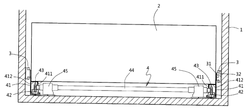
The present invention provides a stabilizing assembly of drawable carrier.
Referring
to FIGS. 1 through 4, a cabinet body 1 is installed with a predetermined
number of
drawable carriers (such as drawers, baskets, shelves, etc.), as one said
drawable carrier 2
3a
CA 02699699 2011-04-26
is provided in the presently shown embodiments. The drawable carrier 2 is
configured to
be pushed or drawn to slide into or out from the cabinet body 1. For this end,
a drawer
slide 3 is provided between each of two laterals of the drawable carrier 2 and
the cabinet
body 1. The drawer slide 3 includes a guiding member 31 fixed to the drawable
carrier 2
and a sliding rail 32 fixed to the cabinet body 1 correspondingly so that the
guiding
member 31 and the sliding rail 32 mutually engage in a slidable and longwise
extendable
manner. In addition, a retaining device 4 is provided between a bottom of the
drawable
carrier 2 and the cabinet body 1. The retaining device 4 is composed of two
rails 41 fixed
to two laterals of the drawable carrier 2 and a rolling shaft rolling along
the two rails 41.
Therein, each of the rails 41 has a bottom embedded therein with a rack 42
that has a
rack 421. The rack 42 further has a bottom equipped with a raised positioning
portion
422, while the corresponding rail 41 has a positioning hole 410, so that when
the
positioning portions 422 are positioned by the positioning holes 410, the
racks 42 engage
with the rails 41 without shifting. Moreover, the rolling shaft includes two
gears 43 that
are configured to engage with the racks 421 and settled at two ends of a rod
44. More
particularly, each of the gears is mounted around a bush 432. The rod 44 has
its two ends
formed with toothed combining holes 441. Each of the bushes 432 has its end
near the
gear 43 formed as a tubular shape so as to define a well therein. The well is
provided
with a combining portion 431 to be fittingly received in the toothed combining
hole 441,
so that the rod 44 and the gears are mutually positioned both in the radially
inward and
outward directions, thereby limiting the gears 43 to slant with respect to the
rod 44 and
allowing the two gears 43 linked through the rod 44 to rotate simultaneously.
Moreover,
two retained portions 433 are formed on the bushes 432 near the two gears 43,
respectively, while two opposite supporting seats 45 are provided on the
cabinet body 1
facing the front bottom of the drawable carrier 2. The two bushes 432
connected to the
two ends of the rod 44 are easily received in two top-opened long notches 451
each on a
said supporting seat 45 while the bushes 432 are allowed to shift vertically
in the long
notches 451. In addition, a stop unit is provided on the rails 41 toward the
bushes 432
facing the racks 421 on the rails 41. The stop unit herein includes two stop
portions 411
each first extending horizontally from a top portion of the rail 41 near the
gear 43, then
4
CA 02699699 2012-06-05
extending vertically downward to cover the gear's top and one lateral, and
further
extending vertically downward. The stop portion 411 has a terminal separated
from the
retained portion 433 of the bush 432 by a predetermined distance.
Thereby, when the drawable carrier 2 receives a force that makes it get drawn
out
from or pushed into the cabinet body 1, the sliding drawable carrier 2 is
guided by not
only the drawer slides 3 but also the retaining device 4. The engagements
between the
racks 421 at the two laterals of the drawable carrier 2 and the set
vertically, rotating
simultaneously, gears 43 orient and guide the sliding drawable carrier 2
without swing
and deviation so as to achieve smoother slide of the drawable carrier 2. On
the other
hand, when the drawable carrier 2 is drawn or pushed at one of the lateral
edge of its
facade furthest from the center, the drawable carrier 2 will move with one
side seriously
exceeding the other side. Consequently, the engagements between the two gears
43 and
the racks 421 receive unbalanced components of force, and the gears 43 may
disengage
from the racks 421. Especially, when the drawable carrier 2 is big and bulky,
such
isengagement is more likely to happen. Structurally, the gears 43 might be
stopped by
the bottom of the drawable carrier 2 or a ceiling 412 of the rails 41 from
escaping.
However, for allowing the gears 43 to rotate smoothly, a relatively large
distance is left
between the gear 43 and the ceiling 412, so when the force exerted on the
drawable
carrier 2 is significantly unbalanced, the two gears 43 can repeat the process
of climbing
teeth of the racks 421 to derail and getting retained by the ceiling 412 to
return to the
racks 421. Consequently, continuous moving the drawable carrier 2 makes the
gears 43
keep jogging, in turn making tooth tops of the gears 43 intermittently ram the
ceiling
412, which brings about undesired noise.
Thus, for further preventing the jog of the gears 43 and the consequent noise,
the
present invention is such configured that the distance between the terminal of
the stop
portion 411 of the rail 41 and the retained portion 433 of the bush 432 is
much smaller
than the distance between the upmost tooth of the gears 43 and the ceiling
412. Thereby,
when the drawable carrier 2 receives unbalanced force and disengagement
between the
gears 43 and the racks 421 happens, the terminal of the stop portion 411 stops
the
retained portion 433 (or the bush 432) so that the gear 43 is prohibited from
jogging and
5
CA 02699699 2011-04-26
in turn contacting the ceiling 412. Besides, since the retained portion 433
(or the bush
432) has a round sectional shape, the retained portion 433 and the terminal of
the stop
portion 411 are in smooth contact, and no intermittent impacting noise can
thus occur.
Additionally, since the vertically extending segment of the stop portion 411
covers the
exposed lateral of the gear 43, the engagement between the gears 43 and the
racks 421 is
ensured, so the drawable carrier 2 is allowed to slide along the set direction
stably and
smoothly, thereby preventing deviation of the drawable carrier 2 and
consequent noise.
While the retaining device 4 is settled below the drawable carrier 2, the same
assembly may be arranged above the drawable carrier 2 at a rear end of the
drawable
carrier 2, as shown in FIGS. 5 and 6. In this alternative embodiment, two
rails 41 with
racks 421 are fixed to two laterals of the cabinet body 1 while the bushes 432
connected
to two ends of a rod 44 of the rolling shaft are received in two supporting
seats 45 at the
back of the drawable carrier 2. The supporting seats 45 are fixed to two
fixing seats 21
settled at the upper back of the drawable carrier 2. In addition, a stop
portion 411, acting
as the stop unit, extends downward from the rail 41 with a tellninal thereof
extending
toward a side of the bush 432 opposite to another side of the bushes 432
facing the rack
421 on the rail 41 closely adjacent to the retained portion 433.
Alternatively, as shown in
FIG. 7, two rails 41 having racks 421 are fixed to the two opposite laterals
of the cabinet
body 1, and two supporting seats 45 receiving the bushes 432 of the rolling
shaft are
positioned by two fixing seats 21 fixed to the back of the drawable carrier 2.
Similarly, a
stop portion 411, acting as the stop unit, extends first horizontally from a
top portion of
the rail 41 near the gear 43 toward a side of the bush 432 opposite to another
side of the
bushes 432 facing the rack 421, then extending vertically downward to cover
the gear's
top and one lateral, and further extending vertically downward to have a
terminal closely
adjacent to the retained portion 433 of the bush 432.
6