Sélection de la langue

Search

Sommaire du brevet 2699751 

Énoncé de désistement de responsabilité concernant l'information provenant de tiers

Une partie des informations de ce site Web a été fournie par des sources externes. Le gouvernement du Canada n'assume aucune responsabilité concernant la précision, l'actualité ou la fiabilité des informations fournies par les sources externes. Les utilisateurs qui désirent employer cette information devraient consulter directement la source des informations. Le contenu fourni par les sources externes n'est pas assujetti aux exigences sur les langues officielles, la protection des renseignements personnels et l'accessibilité.

Disponibilité de l'Abrégé et des Revendications

L'apparition de différences dans le texte et l'image des Revendications et de l'Abrégé dépend du moment auquel le document est publié. Les textes des Revendications et de l'Abrégé sont affichés :

  • lorsque la demande peut être examinée par le public;
  • lorsque le brevet est émis (délivrance).
(12) Brevet: (11) CA 2699751
(54) Titre français: APPAREIL DE CUISSON A LA VAPEUR COMPRENANT UN SYSTEME D'EVACUATION DE LA VAPEUR
(54) Titre anglais: STEAM COOKING APPARATUS WITH STEAM FLUSHING SYSTEM
Statut: Octroyé
Données bibliographiques
(51) Classification internationale des brevets (CIB):
  • A21B 1/36 (2006.01)
  • A21B 3/00 (2006.01)
  • F24C 14/00 (2006.01)
  • F24C 15/32 (2006.01)
(72) Inventeurs :
  • SAKSENA, ATUL (Etats-Unis d'Amérique)
  • LYONS, LARRY W. (Etats-Unis d'Amérique)
  • RECKNER, MICHAEL B. (Etats-Unis d'Amérique)
(73) Titulaires :
  • PREMARK FEG L.L.C. (Etats-Unis d'Amérique)
(71) Demandeurs :
  • PREMARK FEG L.L.C. (Etats-Unis d'Amérique)
(74) Agent: FINLAYSON & SINGLEHURST
(74) Co-agent:
(45) Délivré: 2013-01-08
(86) Date de dépôt PCT: 2008-09-09
(87) Mise à la disponibilité du public: 2009-03-26
Requête d'examen: 2010-03-16
Licence disponible: S.O.
(25) Langue des documents déposés: Anglais

Traité de coopération en matière de brevets (PCT): Oui
(86) Numéro de la demande PCT: PCT/US2008/075657
(87) Numéro de publication internationale PCT: WO2009/038995
(85) Entrée nationale: 2010-03-16

(30) Données de priorité de la demande:
Numéro de la demande Pays / territoire Date
11/857,479 Etats-Unis d'Amérique 2007-09-19

Abrégés

Abrégé français

La présente invention concerne un système de cuisson à la vapeur qui comprend une chambre de cuisson à la vapeur (14) dotée d'une porte d'accès (16) et un drain (40a, 40b) servant à évacuer la vapeur condensée hors de la chambre de cuisson à la vapeur, le long d'un chemin de drainage. Une unité de génération de vapeur (12) chauffe l'eau pour produire la vapeur. L'unité de générateur de vapeur est reliée pour distribuer la vapeur provenant du générateur de vapeur dans la chambre de cuisson à la vapeur via un premier chemin de vapeur (36a, 36b) pendant une opération de cuisson. L'unité de génération de vapeur est également reliée pour distribuer la vapeur provenant du générateur de vapeur, au chemin de drainage via un second chemin de vapeur (50) pendant une opération d'évacuation de la vapeur.


Abrégé anglais


A steam cooking system includes a
steam cooking chamber (14) having an access door (16)
and a drain (40a, 40b) for draining condensate from the
steam cooking chamber along a drain path. A steam
generator unit (12) heats water to generate steam. The
steam generator unit is connected for delivery of steam
from the steam generator to the steam cooking chamber
via a first steam path (36a, 36b) during a cooking
operation. The steam generator unit is also connected
for delivery of steam from the steam generator to the
drain path via a second steam path (50) during a steam
flushing operation.


Revendications

Note : Les revendications sont présentées dans la langue officielle dans laquelle elles ont été soumises.


WHAT IS CLAIMED IS:

1. A steam cooking system, comprising:
a steam cooking chamber having an access door and a drain for draining
condensate from
the steam cooking chamber along a drain path; and
a steam generator unit for heating water to generate steam, the steam
generator unit
connected for delivery of steam from the steam generator unit to the steam
cooking chamber via
a first steam path during a cooking operation, the steam generator unit also
connected for
delivery of steam from the steam generator to the drain path via a second
steam path during a
steam flushing operation.

2. The steam cooking system of claim 1 further comprising a steam valve that
controls
delivery of steam from the steam generator to the drain path.

3. The steam cooking system of claim 2 further comprising a control connected
to the steam
valve for selectively initiating the steam flushing operation.

4. The steam cooking system of claim 3, wherein steam is delivered to the
drain path at a
rate of between one lb/hr and three lb/hr.

5. The steam cooking system of claim 4 further comprising a one-way valve
along the
second steam path between the steam valve and the drain path for inhibiting
reverse flow of
steam thereby.

6. The steam cooking system of claim 1, wherein at least a portion of the
second steam path
is different from the first steam path.

7. The steam cooking system of claim 1 further comprising a temperature
control system
connected to the drain path, the temperature control system configured to
regulate temperature
of water drained through the drain path.


8. The steam cooking system of claim 1 further comprising a building drain
connected to
the drain path.

9. The steam cooking system of claim 1, wherein the steam cooking chamber is a
first steam
cooking chamber, and wherein the steam generator unit connected for delivery
of steam from
the steam generator to a second steam cooking chamber during the cooking
operation, the second
steam cooking chamber having a second drain path connected for receiving steam
for steam
flushing of the second drain path of the second steam cooking chamber.

10. A method of cleaning a steam cooking system, the method comprising:
generating steam using a steam generator, the steam generator connected to a
steam
cooking chamber for delivery of steam to the steam cooking chamber via a first
steam path
during a cooking operation, the steam cooking chamber having an access door
and a drain for
draining condensate from the steam cooking chamber along a drain path; and
delivering steam from the steam generator to the drain path via a second steam
path
during a steam flushing operation.

11. The method of claim 10 further comprising controlling delivery of steam
from the steam
generator to the drain path using a steam valve.

12. The method of claim 11 further comprising selectively initiating the steam
flushing
operation using a controller connected to the steam valve.

13. The method of claim 12 comprising delivering steam to the drain path at a
rate of
between one lb/hr and three lb/hr.

14. The method of claim 13 further comprising inhibiting reverse flow of steam
from the
drain path by providing a one-way valve along the second steam path between
the steam valve
and the drain path.

6


15. The method of claim 10 further comprising regulating temperature of water
drained
through the drain path using a temperature control system connected to the
drain path.

16. The method of claim 10 further comprising draining the drain path into a
building drain.
17. The method of claim 10 further comprising:
providing a second steam cooking chamber, the second steam cooking chamber
having
an access door and a second drain for draining condensate from the second
steam cooking
chamber along a second drain path; and
delivering steam from the steam generator to the second drain path of the
second cooking
chamber during a steam flushing operation.

7

Description

Note : Les descriptions sont présentées dans la langue officielle dans laquelle elles ont été soumises.


CA 02699751 2012-01-30

STEAM COOKING APPARATUS WITH
STEAM FLUSHING SYSTEM
TECHNICAL FIELD
[0001] The present application relates to steam cookers, and more particularly
to a
steam cooker with steam flushing system.
BACKGROUND
100021 Steam cookers have been successfully employed by restaurants, hospitals
and other food service operations to prepare large quantities of food quickly
and
conveniently. Increases in productivity and efficiency are regularly sought,
for example, to
decrease the time and energy needed to cook the products.
SUMMARY
100031 In an aspect, a steam cooking system includes a steam cooking chamber
having an access door and a drain for draining condensate from the steam
cooking chamber
along a drain path. A steam generator unit heats water to generate steam. The
steam
generator unit is connected for delivery of steam from the steam generator to
the steam
cooking chamber via a first steam path during a cooking operation. The steam
generator
unit is also connected for delivery of steam from the steam generator to the
drain path via a
second steam path during a steam flushing operation.
10004] In another aspect, a method of cleaning a steam cooking system is
provided.
The method includes generating steam using a steam generator. The steam
generator is
connected to a steam cooking chamber for delivery of steam to the steam
cooking chamber
via a first steam path during a cooking operation. The steam cooking chamber
has an
access door and a drain for draining condensate from the steam cooking chamber
along a
drain path. Steam is delivered from the steam generator to the drain path via
a second
steam path during a steam flushing operation.
100051 The details of one or more embodiments are set forth in the
accompanying
drawings and the description below. Other features, objects, and advantages
will be
apparent from the description and drawings, and from the claims.
BRIEF DESCRIPTION OF THE DRAWINGS
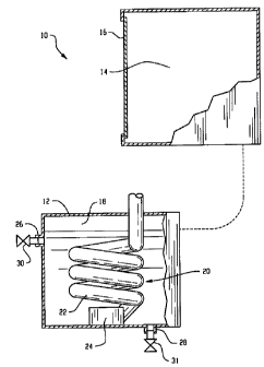
100061 Fig. I is a diagrammatic view of an embodiment of a steam cooking
system;
and

1


CA 02699751 2012-01-30

[00071 Fig. 2 is a diagrammatic view of the steam cooking system of Fig. I
including steam flushing system.
DETAILED DESCRIPTION
[00081 Referring to Fig. 1, a steam cooker system 10 includes a steam
generator 12
for generating steam and a cooking chamber 14 that is in communication with
the steam
generator. The cooking chamber 14 is formed by an insulated housing and
includes a door
16 that is moveable between open and closed positions. In some embodiments not
shown
by Fig. 1, the system 10 may include more than one cooking chamber 14
connected to the
steam generator 12, such as two cooking chambers.
100091 Disposed in a heating chamber 18 of the steam generator 12 may be any
suitable heating system 20. In one embodiment, the heating system 20 includes
a gas heat
exchanger 22 in the form of a submerged heat exchange tube. The heat exchanger
22 is
connected to a burner unit 24 (e.g., a metal fiber, fan driven burner) that is
capable of
generating hot gases for delivery to the heat exchanger. The heat exchanger 22
is located
in the heating chamber 18 such that it can be in a heat exchange relationship
with water
disposed therein. While the illustrated heat exchange relationship is via
submersion with
the heat exchanger, it is possible that hot gas could pass through ducts that
are not
submerged, such as ducts that run across the interior wall of the heating
chamber 18.
Electric heating elements could also be used.
(00101 The heating chamber 18 includes an inlet 26 for ingress of water into
the
heating chamber from a water source and an outlet 28 for egress of water from
the heating
chamber. A valve 30 may-control water flow into the heating chamber, e.g., to
maintain a
desired water level within the heating chamber 18 during steam production.
Water level
sensors may be positioned in the heating chamber 18 for this purpose.
Similarly, a valve
31 may control water flow from the heating chamber 18 during a flushing
operation.
[00111 Referring now to Fig. 2, the steam generator 12 is connected to the
cooking
chamber 14a. In some embodiments, as noted above, the steam generator 12 may
also be
connected to another cooking chamber 14b represented by dashed lines.
[00121 In the illustrated embodiment, a steam header 34 is used to connect
steam
cooking lines 36a and 36b to the steam generator 12. The steam cooking lines
36a and 36b
are, in turn, connected to the cooking chambers l4a and 14b. Steam valves 38a
and 38b
are used to control delivery of steam to the cooking chambers 14a and 14b.

2


CA 02699751 2012-01-30

[0013) Cooking compartment drains 40a and 40b are used for draining condensed
water, other liquids and debris from their respective cooking chambers 14. The
cooking
compartment drains 40a and 40b are connected to a drain line 42, which is, in
turn,
connected to a condenser 44. The drain line 42 carries the water, other
liquids and debris
from the cooking compartment drain 40 to the condenser 44, where the water,
other liquids
and debris can be flushed into a floor drain line 46. Typically, the floor
drain line 46 has a
diameter that is larger than that of the drain line 42 to facilitate the
draining of debris
flushed from the drain line. In some embodiments, the outlet 28 of the steam
generator 12
is also connected to the condenser 44. A cooling water line 48 may be used to
reduce
temperature of the water drained from the steam generator 12 to an acceptable
level. The
condenser 44 may include a temperature sensor 45 for use in determining the
temperature
of the fluids and other particles before they enter the floor drain line 46.
In,some
embodiments, cooling water may be delivered to. the condenser 44 if the
temperature
determined is above a predetermined temperature level permitted by local code.
100141 Occasionally, fat and/or oils drained from the steam cooking chamber 14
can build up in the drain line 42, reducing the effectiveness of the drain
path. Accordingly,
a steam flushing system, referred to generally as element 50, is used to flush
debris, such as
food particles, oils and fats from the drain line 42. Steam flushing system 50
includes a
steam flush line 52 that is connected to the steam generator 12 via the steam
header 34.
Thus, in this embodiment, the steam generator 12 selectively supplies steam to
the cooking
chambers 14 and the steam flushing system 50. A steam valve 54 controls
delivery of the
steam through the steam flushing system 50. In some instances, the steam valve
54
provides steam at rate of between about one lb/hr and about three lb/hr, such
as about 2
lb/hr. The rate of steam delivery may vary, however. As can be seen, the steam
flush line
52 is connected to the drain line 42. A check valve 56 is located between the
steam valve
54 and the drain line 42 to inhibit reverse flow of steam, liquids and debris
thereby. In
some embodiments, a compartment drain cooling water line 58 is also connected
to the
drain line 42 for temperature control in the drain line.
[0015) As steam is delivered through the drain line 42, any solidified fats
and/or
oils will tend to liquefy due to the temperatures effectively cleaning the
drain line 42. In
operation, control 70 may include respective connections to the steam
generator 12 for
controlling production responsive to a cooking chamber interface 72 setting,
connections to
steam cooking line valves 38 to control delivery of steam to the chambers 14,
and

3


CA 02699751 2012-01-30

connection to the steam flush line valve 54 to control steam delivery to the
drain line 42.
The control may be configured to perform the steam flush operation for the
drain line 42 on
a timed basis, e.g., periodically as part of a steam generator shut down
procedure and/or
responsive to a specific control input of the interface 72. In one embodiment,
the steam
flush operation is performed upon shut down where steam is delivered to the
drain line 42
immediately prior to draining of the steam generator 12. After steam is
delivered to the
drain line 42, the water is drained from the steam generator 12, into the
condenser 44. In
some embodiments, the steam flush operation is not connected to shut down. For
example,
the steam flush operation may be initiated manually through a user input.
100161 In the illustrated two chamber system, a separate steam delivery line
36b
and associated valve 38b is provided for the second chamber 14b. The drain 40b
of the
second chamber 14b is connected to the same drain line 42 as the first chamber
14a, such
that a single steam flushing operation via valve 54 is sufficient to clean the
drain paths of
both chambers. In an alternative arrangement, the drain path of the second
chamber 14b is
distinct from the drain path of the first chamber 14a, and two steam flush
lines could be
provided, one for each drain path.
[00171 It is to be clearly understood that the above description is intended
by way
of illustration and example only and is not intended to be taken by way of
limitation. Other
changes and modifications could be made, including both narrowing and
broadening
variations and modifications of the appended claims.

4

Dessin représentatif
Une figure unique qui représente un dessin illustrant l'invention.
États administratifs

Pour une meilleure compréhension de l'état de la demande ou brevet qui figure sur cette page, la rubrique Mise en garde , et les descriptions de Brevet , États administratifs , Taxes périodiques et Historique des paiements devraient être consultées.

États administratifs

Titre Date
Date de délivrance prévu 2013-01-08
(86) Date de dépôt PCT 2008-09-09
(87) Date de publication PCT 2009-03-26
(85) Entrée nationale 2010-03-16
Requête d'examen 2010-03-16
(45) Délivré 2013-01-08

Historique d'abandonnement

Il n'y a pas d'historique d'abandonnement

Taxes périodiques

Dernier paiement au montant de 473,65 $ a été reçu le 2023-09-01


 Montants des taxes pour le maintien en état à venir

Description Date Montant
Prochain paiement si taxe générale 2024-09-09 624,00 $
Prochain paiement si taxe applicable aux petites entités 2024-09-09 253,00 $

Avis : Si le paiement en totalité n'a pas été reçu au plus tard à la date indiquée, une taxe supplémentaire peut être imposée, soit une des taxes suivantes :

  • taxe de rétablissement ;
  • taxe pour paiement en souffrance ; ou
  • taxe additionnelle pour le renversement d'une péremption réputée.

Les taxes sur les brevets sont ajustées au 1er janvier de chaque année. Les montants ci-dessus sont les montants actuels s'ils sont reçus au plus tard le 31 décembre de l'année en cours.
Veuillez vous référer à la page web des taxes sur les brevets de l'OPIC pour voir tous les montants actuels des taxes.

Historique des paiements

Type de taxes Anniversaire Échéance Montant payé Date payée
Requête d'examen 800,00 $ 2010-03-16
Enregistrement de documents 100,00 $ 2010-03-16
Le dépôt d'une demande de brevet 400,00 $ 2010-03-16
Taxe de maintien en état - Demande - nouvelle loi 2 2010-09-09 100,00 $ 2010-08-19
Taxe de maintien en état - Demande - nouvelle loi 3 2011-09-09 100,00 $ 2011-08-19
Taxe de maintien en état - Demande - nouvelle loi 4 2012-09-10 100,00 $ 2012-08-28
Taxe finale 300,00 $ 2012-10-30
Taxe de maintien en état - brevet - nouvelle loi 5 2013-09-09 200,00 $ 2013-08-19
Taxe de maintien en état - brevet - nouvelle loi 6 2014-09-09 200,00 $ 2014-09-08
Taxe de maintien en état - brevet - nouvelle loi 7 2015-09-09 200,00 $ 2015-09-08
Taxe de maintien en état - brevet - nouvelle loi 8 2016-09-09 200,00 $ 2016-09-06
Taxe de maintien en état - brevet - nouvelle loi 9 2017-09-11 200,00 $ 2017-09-05
Taxe de maintien en état - brevet - nouvelle loi 10 2018-09-10 250,00 $ 2018-09-04
Taxe de maintien en état - brevet - nouvelle loi 11 2019-09-09 250,00 $ 2019-08-30
Taxe de maintien en état - brevet - nouvelle loi 12 2020-09-09 250,00 $ 2020-09-04
Taxe de maintien en état - brevet - nouvelle loi 13 2021-09-09 255,00 $ 2021-09-03
Taxe de maintien en état - brevet - nouvelle loi 14 2022-09-09 254,49 $ 2022-09-02
Taxe de maintien en état - brevet - nouvelle loi 15 2023-09-11 473,65 $ 2023-09-01
Titulaires au dossier

Les titulaires actuels et antérieures au dossier sont affichés en ordre alphabétique.

Titulaires actuels au dossier
PREMARK FEG L.L.C.
Titulaires antérieures au dossier
LYONS, LARRY W.
RECKNER, MICHAEL B.
SAKSENA, ATUL
Les propriétaires antérieurs qui ne figurent pas dans la liste des « Propriétaires au dossier » apparaîtront dans d'autres documents au dossier.
Documents

Pour visionner les fichiers sélectionnés, entrer le code reCAPTCHA :


Pour visualiser une image, cliquer sur un lien dans la colonne description du document. Pour télécharger l'image (les images), cliquer l'une ou plusieurs cases à cocher dans la première colonne et ensuite cliquer sur le bouton "Télécharger sélection en format PDF (archive Zip)" ou le bouton "Télécharger sélection (en un fichier PDF fusionné)".

Liste des documents de brevet publiés et non publiés sur la BDBC .

Si vous avez des difficultés à accéder au contenu, veuillez communiquer avec le Centre de services à la clientèle au 1-866-997-1936, ou envoyer un courriel au Centre de service à la clientèle de l'OPIC.


Description du
Document 
Date
(yyyy-mm-dd) 
Nombre de pages   Taille de l'image (Ko) 
Abrégé 2010-03-16 2 72
Revendications 2010-03-16 3 88
Dessins 2010-03-16 2 38
Description 2010-03-16 4 199
Dessins représentatifs 2010-05-18 1 7
Page couverture 2010-05-27 2 43
Dessins représentatifs 2012-12-21 1 8
Page couverture 2012-12-21 2 44
Description 2012-01-30 4 182
Revendications 2012-01-30 3 92
PCT 2010-03-16 4 121
Cession 2010-03-16 12 368
Correspondance 2010-05-17 1 15
Poursuite-Amendment 2011-09-26 2 82
Poursuite-Amendment 2012-01-30 13 463
Correspondance 2012-10-30 1 37
Cession 2014-04-15 45 2 993
Cession 2015-10-02 14 524
Lettre du bureau 2015-10-22 1 34