Sélection de la langue

Search

Sommaire du brevet 2699804 

Énoncé de désistement de responsabilité concernant l'information provenant de tiers

Une partie des informations de ce site Web a été fournie par des sources externes. Le gouvernement du Canada n'assume aucune responsabilité concernant la précision, l'actualité ou la fiabilité des informations fournies par les sources externes. Les utilisateurs qui désirent employer cette information devraient consulter directement la source des informations. Le contenu fourni par les sources externes n'est pas assujetti aux exigences sur les langues officielles, la protection des renseignements personnels et l'accessibilité.

Disponibilité de l'Abrégé et des Revendications

L'apparition de différences dans le texte et l'image des Revendications et de l'Abrégé dépend du moment auquel le document est publié. Les textes des Revendications et de l'Abrégé sont affichés :

  • lorsque la demande peut être examinée par le public;
  • lorsque le brevet est émis (délivrance).
(12) Brevet: (11) CA 2699804
(54) Titre français: PLATEAU EMPILABLE PEU PROFOND
(54) Titre anglais: LOW DEPTH STACKABLE TRAY
Statut: Réputé périmé
Données bibliographiques
(51) Classification internationale des brevets (CIB):
  • B65D 71/70 (2006.01)
(72) Inventeurs :
  • APPS, WILLIAM P. (Etats-Unis d'Amérique)
(73) Titulaires :
  • REHRIG PACIFIC COMPANY (Etats-Unis d'Amérique)
(71) Demandeurs :
  • REHRIG PACIFIC COMPANY (Etats-Unis d'Amérique)
(74) Agent: MACRAE & CO.
(74) Co-agent:
(45) Délivré: 2017-01-10
(22) Date de dépôt: 2010-04-12
(41) Mise à la disponibilité du public: 2010-10-10
Requête d'examen: 2015-03-03
Licence disponible: S.O.
(25) Langue des documents déposés: Anglais

Traité de coopération en matière de brevets (PCT): Non

(30) Données de priorité de la demande:
Numéro de la demande Pays / territoire Date
61/168,260 Etats-Unis d'Amérique 2009-04-10

Abrégés

Abrégé français

Un plateau pour contenants, comme des bouteilles de boisson, comprend une base et une pluralité de colonnes intérieures sétendant vers le haut à partir de la base. Une pluralité de colonnes sétendent vers le haut le long dau moins une partie de la périphérie du plateau. Des parois latérales sétendent le long des côtés du plateau et des parois dextrémité sétendent le long des extrémités du plateau, les colonnes dextrémité étant reliées aux parois latérales par les parois dangle. Ces dernières font saillie vers le haut à une hauteur supérieure à celle des parois latérales et des parois dextrémité et comprennent une ouverture à un bord inférieur de celles-ci pour recevoir une partie dangle dun plateau identique emboîté sous celles-ci. Dans une autre caractéristique indépendante, des séparateurs et/ou les parois comprennent des évidements le long des bords supérieurs pour réduire lencombrement global du plateau.


Abrégé anglais

A tray for containers, such as beverage bottles, includes a base and a plurality of interior columns extending upwardly from the base. A plurality of columns extend upwardly along at least a portion of the periphery of the tray. Side walls extend along the sides of the tray and end walls extend along the ends of the tray, the end walls connected to the side walls by corner walls. The corner walls protrude upwardly higher than the side walls and end walls and include an opening at a lower edge thereof for receiving a corner portion of an identical tray nested therebelow. In another, independent feature, dividers and/or the walls include recesses along uppermost edges to reduce the overall footprint of the tray.

Revendications

Note : Les revendications sont présentées dans la langue officielle dans laquelle elles ont été soumises.


CLAIMS
1. A tray for containers comprising:
a base for supporting containers thereon;
a plurality of interior columns extending upwardly from the base;
a plurality of side columns along sides of the tray;
a plurality of corner columns at corners of the tray;
side walls extending along the sides of the tray; and
end walls extending along the ends of the tray, the end walls connected to the
side walls
by corner walls, the corner walls protruding upwardly higher than the side
walls and end walls,
the corner walls each including an opening at a lower edge thereof for
receiving a corner portion
of an identical tray nested therebelow.
2. The tray of claim 1 wherein the side walls include a plurality of
windows opening
upwardly between adjacent pairs of side columns.
3. The tray of claim 2 wherein the end walls include a plurality of windows
opening
upwardly between adjacent pairs of end columns.
4. The tray of claim 1 wherein the corner walls form outer ledges adjacent
exterior surfaces
of the corner columns.
5. The tray of claim 1 further including a plurality of dividers extending
between the
interior columns.
6. The tray of claim 5 wherein the dividers include recesses adjacent
uppermost edges of the
dividers.
7. The tray of claim 1 wherein the side walls include recesses on interior
surfaces adjacent
uppermost edges thereof.

8. A tray for containers comprising:
a base for supporting containers thereon;
a plurality of interior columns extending upwardly from the base;
a plurality of columns along at least a portion of a periphery of the base;
and
a plurality of single-wall dividers extending between the interior columns,
wherein
the dividers include recesses adjacent uppermost edges of the dividers, such
that the
dividers have reduced thickness at a center of uppermost edges of the
dividers.
9. The tray of claim 8 further including side walls extending along the
sides of the
tray and end walls extending along the ends of the tray.
10. The tray of claim 9 wherein the side walls include a plurality of
windows opening
upwardly between adjacent pairs of side columns.
11. The tray of claim 9 wherein the end walls include a plurality of
windows opening
upwardly between adjacent pairs of end columns.
12. The tray of claim 8 wherein the side walls include recesses on interior
surfaces
adjacent uppermost edges thereof.
13. A tray for containers comprising:
a base for supporting containers thereon;
a plurality of columns along at least a portion of the periphery of the tray;
a plurality of corner columns at corners of the tray;
side walls extending along at least a portion of the sides of the tray; and
corner walls protruding upwardly higher than the side walls, the side walls
connected to the corner walls, the corner walls each including an opening at a
lower edge
thereof for receiving a corner portion of an identical tray nested therebelow,
the base
including openings corresponding to the corner columns, such that corner
columns of an
identical tray would be received through the openings and into correspond
corner columns
6

on the tray, wherein the openings are open outwardly and contiguous with the
opening
through the corner wall.
14. The tray of claim 13 wherein the side walls include a plurality of
windows opening
upwardly between adjacent pairs of side columns.
15. The tray of claim 14 further including end walls including a plurality
of windows
opening upwardly between adjacent pairs of end columns.
16. The tray of claim 13 wherein the corner walls form outer ledges
adjacent exterior
surfaces of the corner columns.
17. The tray of claim 13 further including a plurality of dividers
extending between the
interior columns.
18. The tray of claim 17 wherein the dividers include recesses adjacent
uppermost
edges of the dividers.
19. The tray of claim 18 wherein the side walls include recesses on
interior surfaces
adjacent uppermost edges thereof.
7

Description

Note : Les descriptions sont présentées dans la langue officielle dans laquelle elles ont été soumises.

CA 02699804 2010-04-12
LOW DEPTH STACKABLE TRAY
This application claims priority to U.S. Provisional Application Serial No.
61/168,260,
filed April 10, 2009.
BACKGROUND
The present invention relates to a stackable low depth tray for storing and
transporting
beverage containers, such as bottles.
Plastic bottles are widely used as containers for soft drinks and other
beverages. These
bottles are often stored and transported in trays, particularly plastic trays
having side walls, end
walls and dividers dividing pockets between the side walls and end walls.
There are many
known tray designs that are referred to as "low depth" trays in which the side
walls, end walls
and dividers are lower than the height of the stored bottles, and in which the
bottles support the
weight of additional trays and bottles stacked thereon.
SUMMARY
The present invention relates to a stackable low depth tray for storing and
transporting
beverage containers, such as bottles.
The example tray includes a base and a plurality of interior columns extending
upwardly
from the base. A plurality of columns extend upwardly along at least a portion
of the periphery
of the tray. Side walls extend along the sides of the tray and end walls
extend along the ends of
the tray, the end walls connected to the side walls by corner walls. The
corner walls protrude
upwardly higher than the side walls and end walls and include an opening at a
lower edge thereof
for receiving a corner portion of an identical tray nested therebelow. In
another, independent
feature, dividers and/or the walls include recesses along uppermost edges to
reduce the overall
footprint of the tray.
BRIEF DESCRIPTION OF THE DRAWINGS
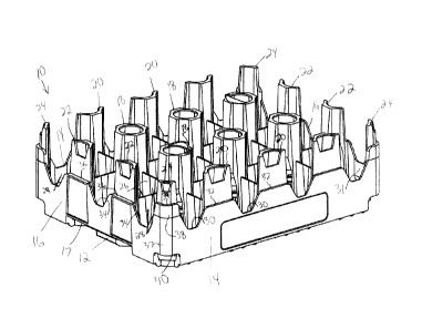
Figure 1 is a perspective view of a tray according to one embodiment of the
present
invention.
Figure 2 is a bottom perspective view of the tray.

CA 02699804 2010-04-12
Figure 3 is a side perspective view of the tray.
Figure 4 is a top perspective view of the tray.
Figure 5 is a top view of the tray.
Figure 6 is a perspective view of the tray with a similar tray stacked
thereon.
Figure 7 is a perspective view of the tray loaded with a plurality of beverage
bottles.
Figure 8 is a top view of the tray and bottles of Figure 7.
Figure 9 illustrates the tray and bottles of Figure 7 broken away.
Figure 10 is a section view of the tray and bottles of Figure 7.
DETAILED DESCRIPTION OF A PREFERRED EMBODIMENT
A tray 10 according to one embodiment of the present invention is shown in
Figure 1.
The tray 10 of this example is configured for holding 1.5 liter plastic
beverage containers in a 3
by 4 arrangement. Modifications to the tray 10 to accommodate bottles of other
sizes and
different numbers of bottles would still be within the scope of this
invention.
The tray 10 includes a base 12, side walls 14 and end walls 16. Handle
openings 17 are
formed at the bottom of each end wall 16. Interior columns 18 (six in this
example) extend
upwardly from the base 12. Side columns 20 extend upwardly from the base 12
along the side
walls 14 of the tray 10. End columns 22 extend upwardly from the base 12
adjacent the end
walls 16. In this configuration, there are three side columns 20 on each side
and two end
columns on each end, but these numbers depend on the number of pockets to be
formed. Corner
columns 24 extend upwardly from the base 12 at each corner of the tray 10.
Dividers 26 extend laterally and longitudinally between adjacent columns 18,
20, 22, 24.
Bottle receiving pockets are defined by the dividers 26 and columns. To
accommodate larger
bottles within a smaller tray footprint, each of the dividers 26 includes a
recessed portion 28 (or a
scallop) adjacent an uppermost edge thereof Similarly, the side walls 14
include a recessed
portion 29 adjacent each window 30 and the end walls 16 include a recessed
portion 31 adjacent
each window 34. The side walls 14 include windows 30 opening upwardly between
columns 20.
The side walls 14 define outer ledges 32 adjacent each side column 20. The end
walls 16 include
windows 34 opening upwardly between end columns 22. The end walls 16 define
outer ledges
36 adjacent the end columns 22.
2

CA 02699804 2010-04-12
In the corners, a corner wall 37 includes an upper portion 38 defining an
outer ledge 39
adjacent the corner column 24. The upper portion 38 of the corner wall 37 is
defined
approximately as the extent to which the corner wall 37 extends above a plane
defined by the
outer ledges 32, 36. The outer ledge 39 adjacent the corner column 24 is
therefore higher than
the outer ledges 32, 36 adjacent the side and end columns 20, 22. The corner
wall 37 includes an
opening 40 at its lower most edge, the opening sufficient in size to receive
the upper portion 38
of the corner wall 37, and in this example, the opening 40 is complementary to
the upper portion
38 of the corner wall 37.
All of the columns in the tray 10 are taller than many known trays, while
still providing a
relatively small footprint (not much larger than the bottles themselves). This
would ordinarily
provide a very narrow, fragile corner column (which is approximately one-
quarter the width of
the interior columns). Therefore, in order to strengthen the corner column 24,
the corner wall 37
is extended upwardly to reinforce the corner column 24. This upper portion 38
of the corner wall
37 is accommodated in the opening 40 to permit normal nesting of the trays.
Figure 2 is a bottom perspective view of the tray 10. As shown, the opening 40
is
generally complementary to the upper portion 38 of the corner wall 37. The
base 12 includes
openings corresponding to the columns, such that the columns of a similar tray
could be received
through the openings and into correspond columns on the tray 10. The openings
through the
base 12 for receiving the corner columns 24 are open outwardly and contiguous
with the opening
40 through the corner wall 37.
Figure 3 is a side perspective view of the tray 10, illustrating the recesses
28 on the
dividers 26 and the recesses 29 on the side walls 14, aligned with each
pocket.
Figure 4 is a top perspective view of the tray 10, again shown in the recesses
29 in the
side walls 14 adjacent each pocket and the recesses 28 in the dividers 26 and
the recesses 31 in
the end walls 16, adjacent each pocket. As shown in Figure 5, the dividers 26
include the
recesses 28 on each side of the divider, such that the divider 26 is
significantly thinner at the
center of its upper edge. The recesses 31 in the end walls 16 and the recesses
29 in the side walls
14 are only formed on the interior surface, adjacent the pocket.
Figure 6 illustrates the tray 10 with a similar tray 10' stacked thereon. As
shown, the side
walls 14' of the upper tray 10' rest on the outer ledges 32 of the lower tray
10. Further, the
upper portion 38 of the corner wall 37 of the lower tray 10 is received within
the corner opening
3

CA 02699804 2016-08-16
40' of the upper tray 10', the edge of which rests on the outer ledge 39 of
the lower tray
10. The configuration of the corners provides a stable stacking configuration,
while also
providing strong corner structure for the tray 10.
Figure 7 illustrates the tray 10 with a plurality of bottles 50 in the
pockets.
Although not visible in this Figure, the bottles 50 would be partially
received in the
recesses 28, 29, 31 (Figure 4).
Figure 8 is a top view of the tray 10 and bottles 50. As shown, the diameter
of the
bottles 50 extends into the recesses 28 in the dividers 26, the recesses 29 in
the side walls
14 and the recesses 31 in the end walls 16. As shown in Figures 9 and 10,
forming the
recess only adjacent the upper edge of the dividers 26 and end walls 16 is
sufficient
because of the normal taper at the bottom of the bottles 50. The recesses 28
taper the
divider 26 to its upper edge, following the curve of the taper of the bottle
50. The recesses
29 in the side walls 14 are similar.
As shown in Figure 10, the outer ledges 39 on the upper portion 38 of the
corner
walls 37 are at a first height. The outer ledges 34 (and outer ledges 32,
Figure 1) are at a
second height, lower than the first height. The dividers 26 are at a third
height, lower
than the outer ledges 32, 34. The windows 30, 34 extend down to a fourth
height, lower
than the third height.
The scope of the claims should not be limited by the preferred embodiments set

forth in the examples, but should be given the broadest interpretation
consistent with the
description as a whole.
4

Dessin représentatif
Une figure unique qui représente un dessin illustrant l'invention.
États administratifs

Pour une meilleure compréhension de l'état de la demande ou brevet qui figure sur cette page, la rubrique Mise en garde , et les descriptions de Brevet , États administratifs , Taxes périodiques et Historique des paiements devraient être consultées.

États administratifs

Titre Date
Date de délivrance prévu 2017-01-10
(22) Dépôt 2010-04-12
(41) Mise à la disponibilité du public 2010-10-10
Requête d'examen 2015-03-03
(45) Délivré 2017-01-10
Réputé périmé 2021-04-12

Historique d'abandonnement

Il n'y a pas d'historique d'abandonnement

Historique des paiements

Type de taxes Anniversaire Échéance Montant payé Date payée
Le dépôt d'une demande de brevet 400,00 $ 2010-04-12
Taxe de maintien en état - Demande - nouvelle loi 2 2012-04-12 100,00 $ 2012-03-26
Taxe de maintien en état - Demande - nouvelle loi 3 2013-04-12 100,00 $ 2013-03-27
Taxe de maintien en état - Demande - nouvelle loi 4 2014-04-14 100,00 $ 2014-03-26
Requête d'examen 800,00 $ 2015-03-03
Taxe de maintien en état - Demande - nouvelle loi 5 2015-04-13 200,00 $ 2015-03-06
Taxe de maintien en état - Demande - nouvelle loi 6 2016-04-12 200,00 $ 2016-03-09
Taxe finale 300,00 $ 2016-11-28
Taxe de maintien en état - brevet - nouvelle loi 7 2017-04-12 200,00 $ 2017-03-08
Taxe de maintien en état - brevet - nouvelle loi 8 2018-04-12 200,00 $ 2018-03-07
Taxe de maintien en état - brevet - nouvelle loi 9 2019-04-12 200,00 $ 2019-03-20
Taxe de maintien en état - brevet - nouvelle loi 10 2020-04-14 250,00 $ 2020-04-01
Titulaires au dossier

Les titulaires actuels et antérieures au dossier sont affichés en ordre alphabétique.

Titulaires actuels au dossier
REHRIG PACIFIC COMPANY
Titulaires antérieures au dossier
APPS, WILLIAM P.
Les propriétaires antérieurs qui ne figurent pas dans la liste des « Propriétaires au dossier » apparaîtront dans d'autres documents au dossier.
Documents

Pour visionner les fichiers sélectionnés, entrer le code reCAPTCHA :


Pour visualiser une image, cliquer sur un lien dans la colonne description du document. Pour télécharger l'image (les images), cliquer l'une ou plusieurs cases à cocher dans la première colonne et ensuite cliquer sur le bouton "Télécharger sélection en format PDF (archive Zip)" ou le bouton "Télécharger sélection (en un fichier PDF fusionné)".

Liste des documents de brevet publiés et non publiés sur la BDBC .

Si vous avez des difficultés à accéder au contenu, veuillez communiquer avec le Centre de services à la clientèle au 1-866-997-1936, ou envoyer un courriel au Centre de service à la clientèle de l'OPIC.


Description du
Document 
Date
(yyyy-mm-dd) 
Nombre de pages   Taille de l'image (Ko) 
Abrégé 2010-04-12 1 18
Description 2010-04-12 4 189
Revendications 2010-04-12 3 87
Dessins 2010-04-12 10 645
Dessins représentatifs 2010-09-14 1 37
Page couverture 2010-09-24 1 65
Revendications 2016-08-16 3 90
Description 2016-08-16 4 187
Dessins représentatifs 2016-12-19 1 28
Page couverture 2016-12-19 1 59
Cession 2010-04-12 2 69
Correspondance 2010-05-25 12 392
Correspondance 2010-05-13 1 16
Poursuite-Amendment 2015-03-03 1 28
Demande d'examen 2016-02-29 3 229
Modification 2016-08-16 5 154
Taxe finale 2016-11-28 1 30