Sélection de la langue

Search

Sommaire du brevet 2699935 

Énoncé de désistement de responsabilité concernant l'information provenant de tiers

Une partie des informations de ce site Web a été fournie par des sources externes. Le gouvernement du Canada n'assume aucune responsabilité concernant la précision, l'actualité ou la fiabilité des informations fournies par les sources externes. Les utilisateurs qui désirent employer cette information devraient consulter directement la source des informations. Le contenu fourni par les sources externes n'est pas assujetti aux exigences sur les langues officielles, la protection des renseignements personnels et l'accessibilité.

Disponibilité de l'Abrégé et des Revendications

L'apparition de différences dans le texte et l'image des Revendications et de l'Abrégé dépend du moment auquel le document est publié. Les textes des Revendications et de l'Abrégé sont affichés :

  • lorsque la demande peut être examinée par le public;
  • lorsque le brevet est émis (délivrance).
(12) Demande de brevet: (11) CA 2699935
(54) Titre français: APPAREIL PHOTO NUMERIQUE ET PROCEDE D'ESSAI DE LA FONCTION D'UN APPAREIL PHOTO NUMERIQUE
(54) Titre anglais: DIGITAL CAMERA AND METHOD FOR TESTING THE FUNCTION OF A DIGITAL CAMERA
Statut: Réputée abandonnée et au-delà du délai pour le rétablissement - en attente de la réponse à l’avis de communication rejetée
Données bibliographiques
(51) Classification internationale des brevets (CIB):
  • H04N 17/00 (2006.01)
  • G01P 13/00 (2006.01)
(72) Inventeurs :
  • SOERENSEN, KENT (Danemark)
  • THORSEN, PER (Danemark)
  • WEHNER, NIKOLAJ (Danemark)
  • VALBJOERN, KELD BENNER (Danemark)
(73) Titulaires :
  • CARLO GAVAZZI SERVICES AG
(71) Demandeurs :
  • CARLO GAVAZZI SERVICES AG (Suisse)
(74) Agent: SMITHS IP
(74) Co-agent:
(45) Délivré:
(22) Date de dépôt: 2010-04-13
(41) Mise à la disponibilité du public: 2010-10-20
Requête d'examen: 2010-04-29
Licence disponible: S.O.
Cédé au domaine public: S.O.
(25) Langue des documents déposés: Anglais

Traité de coopération en matière de brevets (PCT): Non

(30) Données de priorité de la demande:
Numéro de la demande Pays / territoire Date
DE 102009018095.8 (Allemagne) 2009-04-20

Abrégés

Abrégé anglais


The invention refers to a digital camera 1 which can be used in a motion
sensor 4. In order to be
able to test the function of the camera, a light source 3 is provided which
irradiates at least a part
of the sensing matrix 2. The processor device 5 of the camera judges whether
the output signal of
the sensing matrix 2 corresponds correctly to the light which has irradiated
the sensing matrix 2.
Various test methods are disclosed, such as using varying wavelengths, ON/OFF-
modulation,
dependence on shutter time and illumination of various regions of the sensing
matrix 2.

Revendications

Note : Les revendications sont présentées dans la langue officielle dans laquelle elles ont été soumises.


Claims
1. Digital camera comprising an electronic sensing element (2), characterised
by at least one
radiation source (3, 3') which is adapted to irradiate electromagnetic
radiation onto at least part of
the sensing element (2).
2. Digital camera as claimed in claim 1, characterised in that the digital
camera (1) is part of a
motion sensor device (4).
3. Digital camera as claimed in claim 1 or 2, characterised in that, the
digital camera (1) is a
video camera.
4. Digital camera as claimed in anyone of claims 1 to 3, characterised in that
the digital camera
(1) comprises at least one processor device (5).
5. Digital camera as claimed in claim 4, characterised in that the processor
device (5) includes a
microprocessor.
6. Digital camera as claimed in claim 4 or 5, characterised in that the
processor device (5) is
adapted to control the radiation source (3, 3') to send out radiation onto at
least part of the
sensing element (2).
7. Digital camera as claimed in anyone of claims 4 to 6, characterised in that
the processor
device (5) is adapted to read out signals from the sensing element (2) and is
further adapted to
analyse whether the read out signals correspond correctly to the
electromagnetic radiation which
is irradiated onto the sensing element (2) by the radiation source (3, 3').
8. Digital camera as claimed in anyone of claims 1 to 7, characterised in that
the radiation source
(3) comprises more than one radiation element (3a, 3b, 3c, 3d), wherein each
of the radiation
elements (3a, 3b, 3c, 3d) is directed to different parts of the sensing
element (2).
6

9. Digital camera as claimed in claim 8, characterised in that at least some
of the radiation
elements (3a, 3b, 3c, 3d) emit radiation of different wavelengths.
10. Digital camera as claimed in anyone of claims 1 to 9, characterised in
that the digital camera
(1) comprises a shutter (6) which is adapted to apply radiation onto the
sensing element for a
given time interval.
11. Digital camera as claimed in claim 10, characterised in that the processor
device (5) is further
adapted to analyse whether the read out signals correspond correctly to the
given time interval.
12. Digital camera as claimed in anyone of claims 1 to 11, characterised in
that the digital
camera (1) is provided with a variable gain amplifier (7), wherein the
processor device (5) is
adapted to control the gain factor of the amplifier and is further adapted to
analyse whether the
read out signals correspond correctly to the selected gain factor.
13. Method for testing the function of a digital camera (1), having a sensing
element (2),
particularly a video camera which is part of a sensor device (4),
characterised by the step of
irradiating electromagnetic radiation onto at least part of the sensing
element (2).
14. Method for testing the function of a digital camera (1) as claimed in
claim 13, characterised
by the step of reading out signals from the sensing element (2) and the step
of analysing whether
the read out signals correspond correctly to the electromagnetic radiation
which is irradiated onto
the sensing element (2).
15. Method as claimed in claims 13 or 14, characterised by the step of sending
out radiation
predominantly onto a selected part of the sensing element (2).
16. Method as claimed in claim 15, characterised by the step of sending out
radiation from an
edge of the sensing element (2).
7

17. Method as claimed in anyone of claims 13 to 16, characterised by the step
of sending out
radiation onto the sensing element (2) with an on/off-modulation.
18. Method as claimed in anyone of claims 13 to 17, characterised by the step
of sending out
radiation onto the sensing element (2) with a characteristic variation of the
irradiation intensity
over the sensing element (2).
19. Method as claimed in anyone of claims 13 to 18, characterised by the step
of providing a
shutter (6) for applying radiation onto the sensing element (2) for a given
time interval and by
the step of analysing whether the read out signals correspond correctly to the
given time interval.
20. Method as claimed in anyone of claims 13 to 19, characterised by the steps
of:
a) providing the digital camera (1) with a variable gain amplifier (7);
b) controlling the gain factor of the amplifier and
c) analysing whether the read out signals correspond correctly to the selected
gain factor.
21. Method as claimed in anyone of claims 13 to 20, characterised by the steps
of:
a) irradiating the sensing element (2) with electromagnetic radiation varying
in wavelength as a
function of time;
b) analysing whether the read out signals correspond correctly to the
wavelength of the applied
radiation.
8
Description

Note : Les descriptions sont présentées dans la langue officielle dans laquelle elles ont été soumises.


CA 02699935 2010-04-13
Digital camera and method for
testing the function of a digital camera
Motion sensors, for example motions sensors for door opening, of the prior art
mostly work with
Doppler-Radar. In other words, when an object or person approaches the sensor,
a radar beam
emitted from the sensor will be reflected by the object or person and the
reflected beam will
expierence a frequency shift (Doppler-Effect). The reflected radiation will be
recognized by the
motion sensor. However, objects which move very slowly cannot be detected due
to too low or
non-existent Doppler-Effect.
Using a camera in motion sensors provides better results, especially when
slowly moving or still
objects should be detected. However, cameras can fail due to defects in their
recognition system.
It is therefore an object of the present invention to provide a digital camera
which can be easily
and reliably tested as to its proper function.
It is also an object of the present invention to provide a test method for
testing the function of a
digital camera which may be part of a motion sensor device.
The above-mentioned objects are achieved by a digital camera and a method as
claimed in the
independent claims.
Advantageous embodiments are the subject matter of the dependent claims.
According to particular advantageous embodiments the digital camera comprises
a processor
device which is adapted to read out signals from the sensing element and
analyses whether the
read out signals correspond correctly to the electromagnetic radiation which
is irradiated onto the
sensing element by the radiation source. The radiation source, which may be a
light source, may
comprise several light elements, such as LEDs, which can be controlled
individually. The light
1

CA 02699935 2010-04-13
elements may be selected to emit different wavelengths and/or different
intensities. Also an
on/off-modulation may be provided.
For better understanding of the objects and features of the present invention
a preferred
embodiment will be described in greater detail with reference to the
accompanying drawing:
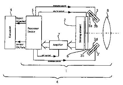
The drawing shows schematically a motion sensor device which includes a
digital video camera
I according to the invention. The digital video camera 1 comprises a sensing
element 2 which
has a square array or matrix of pixels. In front of the sensing element 2
there is shutter 6 which
can be opened or closed. In the open status of the shutter light can travel
from the camera lens 8
to the sensing element 2. In the closed status of the shutter the light
passage from the camera lens
8 to the shutter 6 is obstructed, i.e. no light from outside the camera can
fall onto the sensing
element 2. The digital video camera I further comprises a processor device 5
which receives data
from the sensing element 2. An amplifier 7 with variable gain is provided
which receives' the
pixel data from the sensing element 2 and outputs the data to the processor
device 5. The
processor device 5 is connected to an evaluation station 9. The processor
device 5 is also
connected to the gain control input of the amplifier 7. Further, the processor
device 5 is
connected to the trigger input of the shutter 6.
Radiation sources 3, 3' are provided between the optical camera lens 8 and the
shutter 6. Each of
the radiation sources 3, 3' comprises radiation elements 3a, 3b and 3c, 3d,
respectively. In this
example the radiation elements are light emitting diodes (LED). The radiation
sources 3, 3' are
arranged in such a manner that - when the shutter 6 is open - the radiation
from the radiation
elements 3a, 3b, 3c and 3d falls on the light sensitive face of the sensing
element 2. The radiation
sources 3, 3' are connected to the processing device 5 in such a manner that
each radiation
element 3a, 3b, 3c, 3d can be controlled individually by the processor device
5. Consequently,
each radiation element 3a, 3b, 3c, 3d can be switched ON or OFF and can be
dimmed
independently from the other radiation elements 3a, 3b, 3c, 3d.
2

CA 02699935 2010-04-13
In the test phase a radiation source 3 sends out its light onto the sensing
element directly, i.e. not
through the lens 8 of the camera 1. While in the latter case only a small
fraction of the matrix
would be irradiated, the light will illuminate the whole sensing element 2
when the radiation
source 3 is placed inside the camera 1 housing next to the sensing element 2.
In the following different test setup variations will be discussed:
1) Light applied to the camera sensing element 2 can test the whole sensing
element 2 or parts of
it.
a. The sensing element 2 shall be tested for safety reasons. This means that
the whole picture
field or parts of the field shall detect any object within the field. To
ensure this function the
requirement is that the pixels in the specified field shall respond to the
applied light.
b. When the response from the pixel is detected, the signal passes through the
camera processing
and the gP processing. Dependent of the signal processing the whole sensing
element 2 or part of
the sensing element 2 is included in the test.
2) Variation of shutter time in camera used in 1) can test the whole sensing
element 2 or parts of
the sensing element 2.
a. The camera can be tested as in 1). If light is applied on the camera
sensing element 2 a change
in the shutter time will change the response of each pixel in the camera.
3) Variation of gain in camera used in 1) can test the whole sensing element 2
or parts of the
sensing element 2.
a. The camera can be tested as in 1). If light is applied on the camera chip a
change in the gain
will change the response of each pixel in the camera.
3

CA 02699935 2010-04-13
4) Light applied to the edge of the camera chip used in 1) can test the whole
sensing element 2 or
parts of the sensing element 2.
a. The camera can be tested as in 1). In this situation the light is applied
from the edge of the
camera chip.
5) On/off modulation of light used in 4) can test the whole sensing element 2
or parts of the
sensing element 2.
a. When the light is applied as in 4) turning the light source on and off can
vary the applied
intensity.
6) Characteristic variation of the light intensity over the camera chip used
in 5), can test the
whole sensing element 2 or parts of the sensing element 2.
a. When the light is applied from the edge of the camera chip as in 5), the
intensity will be high
close to the light source and weak in a distance from the light source. This
gives a characteristic
variation of the light intensity over the camera chip.
b. The characteristic intensity variation can test if some addressing failure
is present when the
camera chip is read. In some cases addressing failures can result in the same
readout from to
different pixels despite the light intensity on the two pixels are different.
In this case the failure
can be revealed.
7) Light from a specified number of light sources used in 6) can test the
whole sensing element 2
or parts of the sensing element 2.
a. To ensure revealing of any addressing failure different light sources as in
6) can be combined.
This gives light combinations, which are unique for each pixel.
4

CA 02699935 2010-04-13
8) Light from specified positions of light sources used in 7) can test the
whole sensing element 2
or parts of the sensing element 2.
a. To strengthen uniqueness of the light intensity in 7) positions of the
light sources can be
specified.
9) Light sources with different wavelengths used in a given combination and a
given time
multiplexing used in 8) can test the whole sensor or parts of the sensing
element 2.
a. To strengthen uniqueness of the light intensity in 8) different wavelength
can be used. To
separate the wavelength the light sources shall be sequentially turned on and
off (Time
multiplexing). This will increase the possibility for revealing addressing
failures in a colour-
sensing camera.
5

Dessin représentatif
Une figure unique qui représente un dessin illustrant l'invention.
États administratifs

2024-08-01 : Dans le cadre de la transition vers les Brevets de nouvelle génération (BNG), la base de données sur les brevets canadiens (BDBC) contient désormais un Historique d'événement plus détaillé, qui reproduit le Journal des événements de notre nouvelle solution interne.

Veuillez noter que les événements débutant par « Inactive : » se réfèrent à des événements qui ne sont plus utilisés dans notre nouvelle solution interne.

Pour une meilleure compréhension de l'état de la demande ou brevet qui figure sur cette page, la rubrique Mise en garde , et les descriptions de Brevet , Historique d'événement , Taxes périodiques et Historique des paiements devraient être consultées.

Historique d'événement

Description Date
Inactive : CIB expirée 2023-01-01
Inactive : CIB du SCB 2022-09-10
Inactive : Coagent ajouté 2022-02-22
Exigences relatives à la révocation de la nomination d'un agent - jugée conforme 2021-12-31
Exigences relatives à la nomination d'un agent - jugée conforme 2021-12-31
Exigences relatives à la nomination d'un agent - jugée conforme 2021-12-30
Exigences relatives à la révocation de la nomination d'un agent - jugée conforme 2021-12-30
Le délai pour l'annulation est expiré 2013-04-15
Demande non rétablie avant l'échéance 2013-04-15
Inactive : Abandon. - Aucune rép dem par.30(2) Règles 2012-07-20
Réputée abandonnée - omission de répondre à un avis sur les taxes pour le maintien en état 2012-04-13
Inactive : Dem. de l'examinateur par.30(2) Règles 2012-01-20
Inactive : CIB expirée 2011-01-01
Modification reçue - modification volontaire 2010-11-24
Demande publiée (accessible au public) 2010-10-20
Inactive : Page couverture publiée 2010-10-19
Inactive : Certificat de dépôt - RE (Anglais) 2010-10-13
Modification reçue - modification volontaire 2010-08-05
Lettre envoyée 2010-07-13
Inactive : CIB attribuée 2010-07-12
Inactive : CIB attribuée 2010-07-09
Inactive : CIB en 1re position 2010-07-09
Inactive : CIB attribuée 2010-07-09
Inactive : Correction au certificat de dépôt 2010-06-17
Inactive : Certificat de dépôt - Sans RE (Anglais) 2010-05-13
Demande reçue - nationale ordinaire 2010-05-13
Toutes les exigences pour l'examen - jugée conforme 2010-04-29
Exigences pour une requête d'examen - jugée conforme 2010-04-29
Requête d'examen reçue 2010-04-29

Historique d'abandonnement

Date d'abandonnement Raison Date de rétablissement
2012-04-13

Historique des taxes

Type de taxes Anniversaire Échéance Date payée
Taxe pour le dépôt - générale 2010-04-13
Requête d'examen - générale 2010-04-29
Titulaires au dossier

Les titulaires actuels et antérieures au dossier sont affichés en ordre alphabétique.

Titulaires actuels au dossier
CARLO GAVAZZI SERVICES AG
Titulaires antérieures au dossier
KELD BENNER VALBJOERN
KENT SOERENSEN
NIKOLAJ WEHNER
PER THORSEN
Les propriétaires antérieurs qui ne figurent pas dans la liste des « Propriétaires au dossier » apparaîtront dans d'autres documents au dossier.
Documents

Pour visionner les fichiers sélectionnés, entrer le code reCAPTCHA :


Pour visualiser une image, cliquer sur un lien dans la colonne description du document. Pour télécharger l'image (les images), cliquer l'une ou plusieurs cases à cocher dans la première colonne et ensuite cliquer sur le bouton "Télécharger sélection en format PDF (archive Zip)" ou le bouton "Télécharger sélection (en un fichier PDF fusionné)".

Liste des documents de brevet publiés et non publiés sur la BDBC .

Si vous avez des difficultés à accéder au contenu, veuillez communiquer avec le Centre de services à la clientèle au 1-866-997-1936, ou envoyer un courriel au Centre de service à la clientèle de l'OPIC.


Description du
Document 
Date
(aaaa-mm-jj) 
Nombre de pages   Taille de l'image (Ko) 
Abrégé 2010-04-12 1 14
Description 2010-04-12 5 176
Revendications 2010-04-12 3 106
Dessins 2010-04-12 1 10
Dessin représentatif 2010-09-21 1 9
Certificat de dépôt (anglais) 2010-05-12 1 156
Accusé de réception de la requête d'examen 2010-07-12 1 177
Certificat de dépôt (anglais) 2010-10-12 1 156
Rappel de taxe de maintien due 2011-12-13 1 112
Courtoisie - Lettre d'abandon (taxe de maintien en état) 2012-06-07 1 173
Courtoisie - Lettre d'abandon (R30(2)) 2012-10-14 1 165
Correspondance 2010-06-16 2 62