Sélection de la langue

Search

Sommaire du brevet 2700605 

Énoncé de désistement de responsabilité concernant l'information provenant de tiers

Une partie des informations de ce site Web a été fournie par des sources externes. Le gouvernement du Canada n'assume aucune responsabilité concernant la précision, l'actualité ou la fiabilité des informations fournies par les sources externes. Les utilisateurs qui désirent employer cette information devraient consulter directement la source des informations. Le contenu fourni par les sources externes n'est pas assujetti aux exigences sur les langues officielles, la protection des renseignements personnels et l'accessibilité.

Disponibilité de l'Abrégé et des Revendications

L'apparition de différences dans le texte et l'image des Revendications et de l'Abrégé dépend du moment auquel le document est publié. Les textes des Revendications et de l'Abrégé sont affichés :

  • lorsque la demande peut être examinée par le public;
  • lorsque le brevet est émis (délivrance).
(12) Demande de brevet: (11) CA 2700605
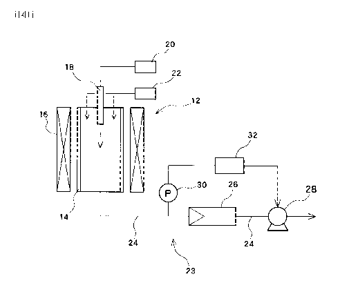
(54) Titre français: APPAREIL DE PRODUCTION ET APPAREIL DE RECUPERATION DE NANOTUBES DE CARBONE OU DE NANOFIBRES DE CARBONE
(54) Titre anglais: CARBON NANOTUBE OR CARBON NANOFIBER PRODUCTION APPARATUS AND RECOVERY APPARATUS
Statut: Morte
Données bibliographiques
(51) Classification internationale des brevets (CIB):
  • C01B 31/02 (2006.01)
  • D01F 9/12 (2006.01)
(72) Inventeurs :
  • SHIRAKI, SHUICHI (Japon)
  • MURAI, TAKEJI (Japon)
  • NAKAGAWA, YUZOU (Japon)
(73) Titulaires :
  • NIKKISO CO., LTD. (Japon)
(71) Demandeurs :
  • NIKKISO CO., LTD. (Japon)
(74) Agent: GOWLING LAFLEUR HENDERSON LLP
(74) Co-agent:
(45) Délivré:
(86) Date de dépôt PCT: 2008-10-16
(87) Mise à la disponibilité du public: 2009-07-02
Licence disponible: S.O.
(25) Langue des documents déposés: Anglais

Traité de coopération en matière de brevets (PCT): Oui
(86) Numéro de la demande PCT: PCT/JP2008/068786
(87) Numéro de publication internationale PCT: WO2009/081645
(85) Entrée nationale: 2010-03-22

(30) Données de priorité de la demande:
Numéro de la demande Pays / territoire Date
2007-334650 Japon 2007-12-26

Abrégés

Abrégé français

Un rejet gazeux contenant des nanotubes de carbone et évacué d'un réacteur (12) est amené à un filtre (26) par l'intermédiaire d'une conduite d'évacuation (24). Un ventilateur (28) est disposé en aval du filtre (26). Le ventilateur (28) est utilisé pour aspirer le rejet gazeux dans la conduite d'évacuation (24). Ainsi, même lorsque le filtre a commencé à se boucher, la pression à l'intérieur de la conduite d'évacuation, du coté amont du filtre, ne peut pas augmenter.


Abrégé anglais


A discharge gas containing carbon nanotubes and discharged
from a reactor (12) is led to a filter (26) through a
discharge pipe (24). A blower (28) is disposed downstream
from the filter (26). The blower (28) is used to suck the
discharge gas in the discharge pipe (24). Thus, even when
the filter has begun to clog, the pressure inside the
discharge pipe on the side upstream from the filter is
inhibited from increasing.

Revendications

Note : Les revendications sont présentées dans la langue officielle dans laquelle elles ont été soumises.


CLAIMS


1. A carbon nanotube or carbon nanofiber
production apparatus comprising:

a reactor to which a material and carrier gas are supplied
and which allows the material to react to synthesize a carbon
nanotube or a carbon nanofiber by a gas phase flow reaction
method;

a discharge pipe through which the carrier gas and a
product resulting from the reaction of the material and
containing the carbon nanotube or carbon nanofiber are
discharged from the reactor;

a filter provided in the discharge pipe to catch the carbon
nanotube or carbon nanofiber;

suction means provided in a portion of the discharge pipe
located downstream of the filter to suck the carrier gas and
the like in the discharge pipe;

a pressure sensor provided in a portion of the discharge
pipe located between the reactor and the filter to detect the
pressure in this portion of the discharge pipe; and

a control section configured to control the suction means
so that the pressure sensed by the pressure sensor is set to
a preset value.


2. The carbon nanotube or carbon nanofiber
production apparatus according to claim 1, wherein the suction
means is a blower.


3. A carbon nanotube or nanofiber recovery


-1-


apparatus configured to recover a carbon nanotube or a carbon
nanofiber synthesized in a reactor by a gas phase flow reaction
method, the carbon nanotube or nanofiber recovery apparatus
comprising:

a filter provided in a discharge pipe connected to the
reactor and through which discharge gas containing the carbon
nanotube or carbon nanofiber is discharged from the reactor,
the filter catching the carbon nanotube or carbon nanofiber;

suction means provided in a portion of the discharge pipe
located downstream of the filter to suck the discharge gas in
the discharge pipe;

a pressure sensor provided in a portion of the discharge
pipe located upstream of the filter to detect the pressure in
this portion of the discharge pipe; and

a control section configured to control the suction means
so that the pressure sensed by the pressure sensor is set to
a preset value.


4. The carbon nanotube or carbon nanofiber
recovery apparatus according to claim 3, wherein the suction
means is a blower.


5. A carbon nanotube or carbon nanofiber
production apparatus comprising:

a reactor to which a material and carrier gas are supplied
and which allows the material to react to synthesize a carbon
nanotube or a carbon nanofiber by a gas phase flow reaction
method;

a discharge pipe through which the carrier gas and a


-2-


product resulting from the reaction of the material and
containing the carbon nanotube or carbon nanofiber are
discharged from the reactor;

a filter provided in the discharge pipe to catch the carbon
nanotube or carbon nanofiber; and

suction means for canceling a pressure loss in the filter
to maintain a pressure in the reactor constant.


-3-

Description

Note : Les descriptions sont présentées dans la langue officielle dans laquelle elles ont été soumises.


CA 02700605 2010-03-22

DESCRIPTION
CARBON NANOTUBE OR CARBON NANOFIBER PRODUCTION APPARATUS AND
RECOVERY APPARATUS


Technical Field

[0001] The present invention relates to a production apparatus
for carbon microfibers, particularly nanotubes each with a
diameter of 0.4 nanometers to several tens of nanometers, and

in particular, to recovery of the synthesized carbon
microfibers.

Background Art

[0002] A production method for carbon nanotubes each with a
diameter of 0.4 nanometers to several tens of nanometers is
known, this method being based on a vapor phase growth method.
In the present specification and the like, examples of carbon
nanofibers include fishbone graphitic-structure nanotubes
each of which is hollow, that is, tubular, but includes a

graphitic layer that is not parallel to a fiber axis,
ribbon-like graphitic fibers that are not hollow, and graphitic
whiskers.

[0003] Carbon nanotubes or carbon nanofibers produced by the
vapor phase growth method need to be recovered by being
separated from gas. Japanese Patent Laid-Open No. 2006-169002

discloses a technique to catch carbon nanotubes or nanofibers
carried by a carrier gas, on a filter such as a net or a plate
-1-


CA 02700605 2010-03-22

with holes. When the carrier gas passes through the net or the
like, the carbon nanotubes or nanofibers are caught on the net
or the like.

Summary of the Invention

[0004] When an obstacle such as a filter is provided in the
carrier gas flow to catch the carbon nanotubes or nanofibers,
an increase in the amount of carbon nanotubes or nanofibers
increases the channel resistance to the carrier gas flow and

thus the pressure on the upstream side of the filter. The
elevated pressure may increase the pressure in a reactor in
which the carbon nanotubes or nanofibers are synthesized, or
disturb the gas flow in the reactor. This may affect the
production process.

[0005] An object of the present invention is to suppress the
adverse effect, on the production process for the carbon
nanotubes or nanofibers, of the amount of carbon nanotubes or
nanofibers caught on the filter.

[0006] In the present invention, a filter configured to catch
carbon nanotubes or nanofibers is provided in a discharge pipe
which is connected to a reactor configured to synthesize the
carbon nanotubes or nanofibers and through which carrier gas
containing the synthesized carbon nanotubes or nanofibers is
discharged from the reactor. Suction means are provided in a

portion of the discharge pipe located downstream of the filter
to suck the discharged gas in the discharge pipe.

[0007] Moreover, a pressure sensor configured to detect the
-2-


CA 02700605 2010-03-22

pressure in the discharge pipe may be provided in a portion of
the discharge pipe located upstream of the filter. Control
means may be provided for controlling the suction means so that
the detected pressure is equal to a preset value.

[0008] Furthermore, a blower may carry out suction to cancel
a pressure loss in the filter to maintain the pressure in the
reactor constant.

[0009] The present invention can reduce the adverse effects
of the amount of carbon nanotubes or nanofibers caught on the
filter, on the environment in which the carbon nanotubes or
nanofibers are synthesized.

Brief Description of the Drawings

[0010] Fig. 1 is a schematic diagram of the configuration of
a carbon nanotube production apparatus according to the present
embodiment.

Description of Symbols

[0011] 10 Carbon nanotube production apparatus, 12 Reactor
unit, 14 Reactor pipe, 16 Heater, 24 Discharge pipe, 26
Filter, 28 Blower (suction means), 30 Pressure sensor, 32
Control section

Description of Embodiments

[0012] An embodiment of the present embodiment will be
described below with reference to the drawings. Figure 1 is
a diagram schematically showing the configuration of a carbon
-3-


CA 02700605 2010-03-22

nanotube production apparatus 10. A reactor unit 12 includes
a reactor pipe 14 installed upright and to which a material is
supplied, and a heater 16 located so as to surround the periphery
of the reactor pipe 14. The reactor pipe 14 is made of ceramics

and shaped like a pipe, preferably a circular pipe. The reactor
pipe 14 is heated by the heater 16 and maintained at a preset
temperature. The reactor pipe 14 includes a material supply
nozzle 18 located at the top and through which a material
supplied by the material supply apparatus 20 is injected into

the reactor pipe 14. Carrier gas is fed from a carrier gas
supply apparatus 22 to the top of the reactor pipe 14 so as to
surround the injected material. The material gas contains a
carbon source, a catalyst, and an auxiliary agent therefor. The
material and carrier gas both fed into the reactor pipe 14

descend through the reactor pipe 14 while being heated by the
pipe wall of the reactor pipe 14. During the descent, carbon
nanotubes are grown and synthesized. This method is called a
vapor phase growth method.

[00131 The generated carbon nanotubes are carried to a recovery
apparatus 23 by carrier gas, unreacted material vapor, and
reacted material vapor. The recovery apparatus 23 includes a
filter 26 installed in the discharge pipe 24 connected to the
bottom of the reactor pipe 14 and a blower 28 serving as suction
means for sucking discharge gas in the discharged pipe. The

filter 26 catches the carbon nanotubes present in the discharged
gas. The filter 26 is preferably bent so as to have an increased
surface area while offering minimized channel resistance. The
-4-


CA 02700605 2010-03-22

blower 28 is installed in a portion of the discharge pipe 24
located further downstream of the filter 26. The blower 28
sucks the discharge gas from a portion of the discharged pipe
24 located upstream of the position where the blower is

installed. The blower 28 allows the discharged gas passing
through the filter to flow at a proper rate even if the filter
26 offers high channel resistance. Furthermore, this
configuration enables operation to be continuously performed
until the filter catches a large number of carbon nanotubes,

compared to the configuration in which the suction based on the
blower is not used.

[0014] A pressure sensor 30 configured to detect the pressure
in the discharge pipe 24 may be provided in a portion of the
discharge pipe 24 located upstream of the filter 26. A control

section 32 configured to control the operational condition of
the blower 28 performs the control based on the pressure in the
discharge pipe detected by the pressure sensor. Preferably,
the rotation speed of the blower 28 is controlled such that the
detected pressure has a preset constant value. The value can

be determined based on reaction conditions in the reactor pipe
14. To allow the rotation speed to be controlled, power can
be supplied to the blower via an inverter. Controlling the
pressure at the position of the pressure sensor, 30 to the
constant value may be considered to be the cancellation of a
pressure loss in the filter 26 by the blower.

[0015] Since the pressure in the portion of the discharge pipe
located upstream of the filter 26 is maintained constant, the
-5-


CA 02700605 2010-03-22

reaction conditions such as the air current and pressure in the
reactor pipe 14 are stabilized, thus improving reaction
efficiency. This also prevents carbon nanotubes from being
attached to the inner wall of the reactor pipe 14.

[00161 In the present embodiment, the carbon nanotube
production apparatus based on the vapor phase growth method has
been described. However, the above-described recovery
apparatus can be applied to production apparatuses configured
to synthesize carbon nanotubes or other carbon nanofibers by
other gas phase flow reaction methods.

-6-

Dessin représentatif
Une figure unique qui représente un dessin illustrant l'invention.
États administratifs

Pour une meilleure compréhension de l'état de la demande ou brevet qui figure sur cette page, la rubrique Mise en garde , et les descriptions de Brevet , États administratifs , Taxes périodiques et Historique des paiements devraient être consultées.

États administratifs

Titre Date
Date de délivrance prévu Non disponible
(86) Date de dépôt PCT 2008-10-16
(87) Date de publication PCT 2009-07-02
(85) Entrée nationale 2010-03-22
Demande morte 2013-10-16

Historique d'abandonnement

Date d'abandonnement Raison Reinstatement Date
2012-10-16 Taxe périodique sur la demande impayée

Historique des paiements

Type de taxes Anniversaire Échéance Montant payé Date payée
Le dépôt d'une demande de brevet 400,00 $ 2010-03-22
Taxe de maintien en état - Demande - nouvelle loi 2 2010-10-18 100,00 $ 2010-08-18
Taxe de maintien en état - Demande - nouvelle loi 3 2011-10-17 100,00 $ 2011-08-24
Titulaires au dossier

Les titulaires actuels et antérieures au dossier sont affichés en ordre alphabétique.

Titulaires actuels au dossier
NIKKISO CO., LTD.
Titulaires antérieures au dossier
MURAI, TAKEJI
NAKAGAWA, YUZOU
SHIRAKI, SHUICHI
Les propriétaires antérieurs qui ne figurent pas dans la liste des « Propriétaires au dossier » apparaîtront dans d'autres documents au dossier.
Documents

Pour visionner les fichiers sélectionnés, entrer le code reCAPTCHA :


Pour visualiser une image, cliquer sur un lien dans la colonne description du document. Pour télécharger l'image (les images), cliquer l'une ou plusieurs cases à cocher dans la première colonne et ensuite cliquer sur le bouton "Télécharger sélection en format PDF (archive Zip)" ou le bouton "Télécharger sélection (en un fichier PDF fusionné)".

Liste des documents de brevet publiés et non publiés sur la BDBC .

Si vous avez des difficultés à accéder au contenu, veuillez communiquer avec le Centre de services à la clientèle au 1-866-997-1936, ou envoyer un courriel au Centre de service à la clientèle de l'OPIC.


Description du
Document 
Date
(yyyy-mm-dd) 
Nombre de pages   Taille de l'image (Ko) 
Page couverture 2010-06-01 2 38
Abrégé 2010-03-22 1 13
Revendications 2010-03-22 3 87
Dessins 2010-03-22 1 8
Description 2010-03-22 6 200
Dessins représentatifs 2010-03-22 1 6
Abrégé 2010-03-23 1 13
Revendications 2010-03-23 3 77
PCT 2010-03-22 7 225
Cession 2010-03-22 6 142
Poursuite-Amendment 2010-03-22 6 137
Taxes 2010-08-18 1 44
Poursuite-Amendment 2010-09-28 1 30
PCT 2010-03-23 4 189