Note : Les descriptions sont présentées dans la langue officielle dans laquelle elles ont été soumises.
CA 02703850 2010-04-27
Device for extracting the flank bones of beheaded, slaughtered fish having
open
abdominal cavities and filleting machine for filleting beheaded, slaughtered
fish
having open abdominal cavities comprising such a device
The invention concerns an apparatus for cutting free the flank bones of
beheaded,
slaughtered fish having open abdominal cavities which are transported on
transport
saddles, comprising an upper bone guide, a lower bone guide and a separating
unit for
detaching fish fillets from the flank bones, wherein the separating unit
includes a
separating means with corresponding counter support and can be moved out of a
standby position into a working position and vice versa. Furthermore the
invention
concerns a filleting machine for filleting beheaded, slaughtered fish having
open
abdominal cavities, comprising dorsal knives for exposing the back spokes as
far as the
backbone, abdominal knives for exposing the belly spokes in the tail region as
far as the
backbone, an apparatus for cutting the flank bones free, separating knives for
separating
the fillets in the tail region from the backbone while cutting through the web
left round
the backbone by abdominal and dorsal knives, an endless conveyor for transport
of the
fish tail first, and a number of fish saddles arranged on the conveyor for
reliably
receiving the fish in their abdominal cavities.
Such apparatuses and filleting machines are used in the fish-processing
industry to fillet
fish automatically, in particular the salmon species. An essential working
step in the
automated filleting of fish is detaching the fillets from the flank bones,
that is, the rib
arches, which extend on both sides of the backbone. In the process the fish
are
transported by means ofthe transport saddles to the individual processing
tools, inter
alia the apparatus for cutting the flank bones free. The upper and lower bone
guides
serve to hold and guide the fish in the optimum processing position on the
transport
saddle. The separating unit is usually arranged on both sides of the fish to
be processed,
so that the fillets can be detached from the flank bones in parallel or with a
time delay.
Detachment of the fillets from the flank bones takes place in the state of the
art, which is
formed e.g. by WO 02/03807 A 1, by means of a scraping tool. In other words,
the
apparatus for cutting the flank bones free is formed by a scraping tool which
is
composed of scraping knives and scraping knife counter supports. Both the
scraping
CA 02703850 2010-04-27
-2-
knives and the scraping knife counter supports are fixed and, in addition to
the capacity
for vertical displacement, can also be swung out laterally. This known
apparatus and
hence also a filleting machine with such an apparatus have the drawback,
however, that
the cut surface is raw from the scraping detachment. Furthermore the
possibilities of
cutting guides are limited by the fixed scraping knives or scraping knife
counter
supports, so that the first flank bones sometimes remain in the fillet. This
results in
increased requirements for subsequent processing, leading to additional costs.
It is therefore the object of the present invention to propose an apparatus
and a method
for cutting the flank bones free, which ensures an improved cut surface and
individual
cutting guides. Furthermore it is the object of the invention to propose a
corresponding
filleting machine.
This object is achieved by an apparatus having the features mentioned
hereinbefore by
the fact that the separating means is a rotating circular knife and the
counter support is a
fixed element, both the circular knife and the element being pivotable about
two axes,
and the element being movable relative to the circular knife and independently
thereof.
The term "fixed" in connection with the counter support means that the counter
support
is indeed movable as a unit, e.g. pivotable, but by contrast with rotation of
the circular
knife does not perform an active cutting or separating movement such as e.g.
rotation,
oscillation or the like. Due to active cutting of the fillets from the flank
bones by the
rotating circular knife, a smooth cut surface is produced, wherein the
positioning of the
counter support relative to the circular knife assists this effect. In other
words, the
design according to the invention makes it possible for the counter support to
be moved
into an optimum position relative to the circular knife while the flank bones
are cut free,
so that a cut which is as smooth and perfect as possible takes place.
An appropriate development of the invention is distinguished in that the fixed
element is
sickle-shaped. The sickle-shaped or half-moon-shaped design serves to provide
a
cutting limit in a longer cutting region of the circular knife, that is, along
a circular
segment of the circular knife. Due to the linear provision or design of the
counter
support, in particular the cutting thickness can be altered over the cutting
length.
CA 02703850 2010-04-27
-3-
Preferably, each circular knife and the corresponding counter support have a
common
pivot axis and one further separate pivot axis, each. To put it another way,
at least three
pivot axes are provided. One pivot axis allows the apparatus or the unit
consisting of
circular knife and counter support to be pivoted up and down in general. A
second pivot
axis allows the circular knife to be moved towards and away from the bone
guides. The
third pivot axis allows the counter support to pivot towards and away from the
bone
guides. The movements of the second and third axes serve on the one hand to
adjust in
particular the cutting thickness. On the other hand the pivot movement about
the second
and third pivot axes allows a movement out of the standby position into the
processing
position and back.
Advantageously, each counter support has an additional pivot axis. Thus, each
counter
support is movable about a total of three pivot axes. As a result, in
particular the cutting
angle relative to the circular knife is variable. In other words, an X
position relative to
the circular knife can be obtained by the additional pivot movement.
A preferred development of the invention is characterised in that in the
region of the
lower bone guide are formed recesses for receiving the counter supports as
well as the
circular knives. Hence the counter supports and the circular knives can stop
in the
standby position outside the region of transport of the fish, which,
particularly when the
tail region which leads in the direction of fish travel is guided over into
the region of the
circular knives, prevents the circular knives from penetrating the fish before
the
beginning of the flank bones in the direction of fish travel or from breaking
up the fish
in the flesh structure by guiding it over covering cover means. To put it
another way,
additional deflectors which would be arranged between the fish and the
circular knives
can be dispensed with.
The object is also achieved by a filleting machine mentioned hereinbefore,
which is
distinguished in that the apparatus for cutting the flank bones free is
designed according
to any of claims I to 12. The resulting advantages have already been mentioned
in
connection with the apparatus for cutting them free, so that at this point
reference is
made to the corresponding passages, to avoid repetition.
CA 02703850 2010-04-27
-4-
Further appropriate and/or advantageous features and embodiments are apparent
from
the subsidiary claims and the description. A particularly preferred embodiment
is
described in more detail with the aid of the attached drawings. The drawings
show:
Figure 1 a perspective view of an apparatus according to the invention at a
stage at
which a fish encounters the circular knives,
Figure 2 the apparatus according to Figure 1 in a front view,
Figure 3 a perspective view of the apparatus according to the invention at a
stage
at which detachment of the fillets from the flank bones is beginning,
Figure 4 the apparatus according to Figure 3 in a front view,
Figure 5 a perspective view of the apparatus according to the invention at a
stage
at which detachment of the fillets from the flank bones has progressed
further,
Figure 6 the apparatus according to Figure 5 in a front view, and
Figure 7 a side view of the transport saddle, indicating the bone structure.
The apparatus shown serves to cut the flank bones free (hereinafter also
referred to as
the ribs) from beheaded, slaughtered salmon having open abdominal cavities,
which are
transported tail first in the direction of fish travel. The apparatus may,
however,
naturally also be used to detach the fillets from the ribs of other fish
species. Also, use
of fish which are transported headfirst in the direction of fish travel is
possible.
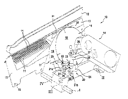
With the apparatus 10 shown in Figures 1 to 6 for cutting the flank bones I I
free, for
the sake of greater clarity only one apparatus 10 for processing one side of
the fish is
shown and described. In practice, however, the apparatuses 10 described below
are
located on both sides of a fish to be processed, so that the two fillets of a
fish on both
sides can be detached from the flank bones 1 1 preferably at the same time,
but
CA 02703850 2010-04-27
5-
optionally also with a time delay. Alternatively, two apparatuses 10 arranged
on
opposite sides of a fish can also form a common apparatus 10, in which case
processing
on both sides can take place in synchronisation or independently of each
other.
The apparatus 10 for cutting the flank bones I I free comprises an upper bone
guide 12,
a lower bone guide 13 and a separating unit 14. By means of the bone guides
12, 13 the
fish to be processed, which is usually transported on a transport saddle 15
into the
region of the separating unit 14, is kept in a defined position such that the
fish lies in a
defined position in relation to the separating unit 14. The transport saddle
15 is
described in more detail below. The separating unit 14 has a separating means
16 with
which is associated a corresponding counter support 17. The separating unit 14
or the
separating means 16 with the coulter support 17 is movable out of a standby
position
(see e.g. Figure 1) in which engagement of the separating means 16 in the fish
is
prevented, into a processing position (see Figures 3 and 5) in which the
separating
means 16 cuts the flank bones 1 I free, and back.
The separating means 16 of the apparatus 10 is designed as a rotating circular
knife 18
and can be driven in rotation at variable speed by means of a drive, not shown
explicitly. The counter support 17 is a fixed element 19. The term "fixed" has
already
been defined or explained above, which is why repetition will be dispensed
with at this
point. The fixed element 19 is preferably sickle-shaped or half-moon-shaped
and
arranged in front of the circular knife 18 in the direction of fish travel
(see arrow F).
Both the circular knife 18 and the element 19 are pivotable about two axes, in
order on
the one hand to be movable out of the standby position into the processing
position and
back, and on the other hand to be able to perform the necessary cutting
movements. For
processing both sides of the fish, the separating means 16 can comprise two
circular
knives 19 with corresponding counter support 17, wherein the two circular
knives 19
and the associated counter support 17 are arranged on opposite sides of the
fish to be
processed.
As already mentioned, each circular knife 18 and each element 19 is pivotable
about at
least two pivot axes. A circular knife 18 and an element 19 of one processing
side have
a common pivot axis 1. Due to the movement about the common pivot axis 1, the
CA 02703850 2010-04-27
-6-
circular knife 18 and the element 19 are movable up and down in relation to
the plane of
transport of the fish. Furthermore, the circular knife 18 is movable about a
pivot axis 11
by means of which the circular knife 18 is movable towards and away from the
bone
guides 12, 13, that is, transversely to the direction of fish travel. The
element 19 is
movable about a pivot axis III independent of the pivot axis 11. Due to the
movement
about the pivot axis 111, the element 19 is movable towards and away from the
bone
guides 12, 13, that is, transversely to the direction of fish travel. The
pivot axes II and
III also allow a movement of circular knife 18 and element 19 relative to each
other.
Optionally, the element 19 has a further, additional pivot axis IV. By means
of a
movement about the pivot axis IV, the element 19 is also movable towards and
away
from the bone guides 12, 13, that is, transversely to the direction of fish
travel. The
pivot movements of the element 19 about the pivot axes III and IV can be
superimposed
on each other like the movements about the other pivot axes.
The counter support 17 or the element 19 is operatively connected to an
adjusting
element 20. To put it another way, the element 19 is assigned an adjusting
element 20
by means of which the element 19 is displaceable particularly in relation to
the circular
knife 18 for adjusting a cutting angle and/or the cutting thickness. The
adjusting element
comprises a stop element 21 which has two stops 21a and 21b and is operatively
20 connected to adjusting screws 22, 23. Instead of the adjusting screws 22,
23, other
adjusting members can be used. Furthermore, the adjusting element 20 comprises
a
supporting element 24. The supporting element 24 and the stop element 2I have
a
common pivot axis, namely the pivot axis IV. In other words, both the stop
element 2 1
and the supporting element 24 are pivotable about the pivot axis IV.
On the supporting element 24, which at a free end 25 is connected to the
element 19, are
arranged the adjusting screws 22, 23 or the like. The supporting element 24
and the stop
element 21 are seated on a common shaft 26 which forms the pivot axis IV. The
supporting element 24 or the stop element 21 is assigned an actuating element
27. The
actuating element 27 is for example a pneumatic cylinder 28 which is attached
on the
one hand by a support frame 29 to the supporting element 24 and on the other
hand to
the stop element 21. But the arrangement and design of the actuating element
27 can be
CA 02703850 2010-04-27
-7-
realized in a different manner. By means of the actuating element 27 the pivot
movement about the pivot axis IV can be achieved.
In the region of the lower bone guide 13 are formed recesses 30, 31 for
receiving the
circular knife 18 and the element 19. The recess 30 is adapted to the contour
of the
circular knife 18 and has a depth which allows the circular knife 18 to lie
completely
within the bone guide 13. "Completely" refers to the fact that the circular
knife 18 in the
standby position lies in the bone guide 13 in such a way that it does not
protrude beyond
the bone guide 12 transversely to the direction of fish travel. The recess 31
is adapted to
the sickle shape of the element 19 and also designed in depth in such a way
that the
element 19 in the standby position lies correspondingly completely within the
bone
guide 13. However, the design of the recesses 30, 31 may of course vary.
In Figure 7 the transport saddle 15 is shown on a larger scale. The transport
saddle 15 is
basically constructed in a conventional manner, namely with a saddle body 32
which is
attached by means of supporting elements 33, 34 to an endlessly rotating
transport chain
(not shown). On the upper side facing towards the fish, the saddle body 32 has
fixing
elements 35 which are preferably designed as saw teeth. The fish is pushed
onto the
transport saddle 15 head region first, wherein the transport saddle 15 lies at
least
partially in the abdominal cavity. In the front region facing towards the
fish, the
transport saddle 15 or saddle body 32 slopes down, forming a slope 36, making
it easier
to thread the fish into/onto the transport saddle 15. The slope 36 is adjoined
by a
substantially vertically extending region 37 which forms a stop face 38. From
the stop
face 38, the saddle body 32 runs in the direction of the supporting elements
33. Due to
the stop face 38, which butts against the end of the abdominal cavity located
in the tail
region of the fish when the fish is threaded on with its abdominal cavity
open, the fish is
positioned optimally.
Below, the principle of the method is described in more detail in particular
with the aid
of the sequence of Figures 1, 3, 5.
The fish to be processed is beheaded and slaughtered before placing it on the
transport
saddle 15, so that the fish has its abdominal cavity open. Then the "headless"
fish is
CA 02703850 2010-04-27
-8-
pushed head region first in the direction opposite the direction of fish
travel F (see
Figure 7) onto the transport saddle 15 until the stop face 38 of the transport
saddle 15
encounters the end of the abdominal cavity. The fish positioned in this way is
preferably
transported tail first in the direction of fish travel through the filleting
machine. The fish
to be processed is transported on the transport saddle 15 inter alia into the
region of the
apparatus 10. To gently guide the tail region, which is leading in the
direction of fish
travel, the circular knife 18 and the element 19 are located in the standby
position in the
recesses 30, 31 (see e.g. Figure 1), so that the tail region can pass through
the separating
unit 14 without impairment/damage. As soon as the region of the flank bones I
1 is
locatedjust in front of the circular knife 18 in the direction of fish travel,
the circular
knife 18 is pivoted about the two pivot axes I and II out of the recess 30 and
into the
processing position. In parallel, the element 19 is pivoted correspondingly
about the two
pivot axes I and III (see Figure 3). The size of the delivery or pivot
movements can be
chosen individually as a function of the fish size.
The element 19 abuts with its upper tip in the recess 31 against the lower
bone guide 13.
While the flank bones 1 1 are cut free, the element 19 is adjusted relative to
the circular
knife 18 in such a way that a smooth cut takes place. The position of the
element 19
relative to the circular knife 18 can be varied in particular by activating
the element 19
via the actuating element 27. To put it another way, by actuation of the
actuating
element 27 the angle of the element 19 relative to the circular knife 18 can
be adjusted
within a fixed range between the two stops 21 a and 21 b of the stop element
21. This
results in different cutting angles and cutting thicknesses. A maximum or
minimum
cutting thickness is reached when the stops 21a, 21b butt against the
adjusting screws
22, 23. Between the stops 21a, 21b the element 19 works against the selected
air
pressure of the cylinder 28 and so automatically adjusts the cutting
thickness. As
already mentioned, the circular knives 18 rotate to cut the fillets free. But
there is also
the possibility of varying the cutting speed of the circular knives 18
preferably after
penetration of the fish, and in particular also reducing it. Even temporary
stopping of the
circular knives 18 while the fillets are cut free is possible. In such a case
the circular
knives 18 would act as a kind of scraping knife.
CA 02703850 2010-04-27
-9-
Due to adjustment of the stop screws or adjusting screws 22, 23, it can
further be
determined whether the membrane (white belly skin) is to remain on the fillet,
or
whether the membrane is to be separated from the fillet. With salmon, the
membrane is
for example located at the lower edge of the abdominal cavity. In case of the
adjustment
of the adjusting screws 22, 23 set in Figures 3 and 5, the membrane is
separated from
the fillet and remains on the flank bones 11. The adjustment of the cutting
angles and
cutting thickness can be varied while cutting free, so that e.g. the gap
between circular
knife 18 and element 19 is greater at the beginning of the abdominal cavity
than in the
middle or at the end of the abdominal cavity. As a result the flank bones 1 1
can more
easily pass between the element 19 and the circular knife 18.