Note : Les descriptions sont présentées dans la langue officielle dans laquelle elles ont été soumises.
CA 02705238 2010-05-07
WO 2009/061195 PCT/NL2008/050707
1
DROPLET SELECTION MECHANISM
The invention relates to a droplet selection device for a continuous printing
system. In this connection, by a continuous jet printing technique is meant
the
continuous generation of drops which can be utilized selectively for the
purpose of a
predetermined printing process. The supply of drops takes place continuously,
in
contrast to the so-called drop-on-demand technique whereby drops are generated
according to the predetermined printing process.
A known apparatus is described, for instance, in US 3,709,432. This document
discloses a so-called continuous jet printer for printing materials using a
first droplet
ejection system arranged to generate a continuous stream of first droplets
from a fluid
jetted out of an outlet channel. During the exit of the fluid through an
outlet channel,
a pressure regulating mechanism provides, with a predetermined regularity,
variations in the pressure of the viscous fluid adjacent the outflow opening.
This leads
to the occurrence of a disturbance in the fluid jet flowing out of the outflow
opening.
This disturbance leads to a constriction of the jet which in turn leads to a
breaking up
of the jet into drops. This yields a continuous flow of egressive drops with a
uniform
distribution of properties such as dimensions of the drops.
The publication shows a gas jet mechanism to selectively deflect the drops.
The
fluid jet length is controlled of droplets generated by the regulating
mechanism. The
deflection properties of the droplets differ from that of the jet, so that
droplets can be
selectively deflected.
In one aspect, the invention aims to provide an alternative to the continuous
droplet ejection system that is used to deflect the continuous stream of the
first
droplets.
According to an aspect of the invention, a droplet selection device for a
continuous printer is provided, comprising: a droplet ejection system arranged
to
generate a continuous stream of droplets from a first fluid jetted out of an
outlet
channel; and a jet system arranged to generate a second jet for colliding the
jet into
the stream of droplets wherein the jet system comprises a deflector to
selectively
deflect the second jet into the continuous stream of droplets
CA 02705238 2010-05-07
WO 2009/061195 PCT/NL2008/050707
2
According to another aspect of the invention, a method of selecting droplets
from a fluid jet ejected from a continuous printer is provided, comprising
generating a
continuous stream of droplets from a first fluid jet jetted out of an outlet
channel,
generating a second jet for colliding into the droplets so as to selectively
deflect the
droplets from a predefined printing trajectory wherein the second jet is
selectively
deflected and collided with a predefined first droplet.
It is noted that in this connection, the term jet is used to identify a
continuous
longitudinal shaped volume of material moving through space, to denote the
contrast
with (a series of) droplets, each formed of generally spherical isolated
volumes.
Without limitation, droplet frequencies may be in the order of 2-80 kHz, with
droplets smaller than 80 micron.
In addition, by virtue of high pressure, fluids may be printed having a
particularly high viscosity such as, for instance, viscous fluids having a
viscosity of
more than 300.10-3 Pa-s when being processed. In particular, the predetermined
pressure may be a pressure up to 600 bars.
Other features and advantages will be apparent from the description, in
conjunction with the annexed drawings, wherein:
Figure 1 shows schematically a first embodiment of a printing system for use
in the present invention;
Figure 2 shows a first embodiment of a deflecting jet system;
Figure 3 shows a second embodiment of deflecting jet system;
Figure 4 shows a third embodiment of deflecting jet system; and
Figure 5 shows an alternative embodiment of deflecting jet system.
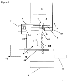
Figure 1 shows a first schematic embodiment of a continuous printer head 1
according to the invention. The print head 1 comprises a first droplet
ejection system
10 arranged to generate a continuous stream of first droplets 6 from a fluid
jetted out
of an outlet channel 5. The droplet ejection system 10 comprises a chamber 2,
defined
by walls 4. Chamber 2 is suited for containing a pressurized liquid 3, for
instance
pressurized via a pump or via a pressurized supply (not shown). The chamber 2
comprises an outlet channel 5 through which a pressurized fluid jet 60 is
jetted out of
CA 02705238 2010-05-07
WO 2009/061195 PCT/NL2008/050707
3
the channel and breaks up in the form of droplets 6. Schematically shown,
actuator 7
is formed near the outlet channel 5 and may be vibrating piezo-electric or
magnetostrictive member. By actuation of the actuator 7, a pressure pulse is
formed,
breaking up the fluid jet and accordingly forming smaller monodisperse
droplets 6.
The outflow opening 5 is included in a relatively thin nozzle plate 4 which
can
be a plate manufactured from metal foil, of a thickness of 0.3 mm for example
0.1- 3
mm. The outflow opening 5 in the plate 4 has a diameter of 50 m in this
example. A
transverse dimension of the outflow opening 5 can be in the interval of 2-500
m. As
an indication of the size of the pressure regulating range, it may serve as an
example
that at an average pressure up to 600 bars [= 600 x105 Pa]. The print head 10
may be
further provided with a supporting plate 40 which supports the nozzle plate 4,
so that
it does not collapse under the high pressure in the chamber. Examples of
vibrating
actuators may be found for example in W02006/101386 and may comprise a
vibrating
plunger pin arranged near the outlet channel 5.
The distance interval of the vibrating plunger pin may depend on the viscosity
of the fluid. When printing fluids having a high viscosity, the distance from
the end to
the outflow opening is preferably relatively small. For systems that work with
pressures up to 5 Bars [=5.105 Pa], this distance is, for instance, in the
order of 1.5
mm. For higher pressures, this distance is preferably considerably smaller.
For
particular applications where a viscous fluid having a particularly high
viscosity of,
for instance, 300-900.10-3 Pa.s, is printed, an interval distance of 15-30 m
can be
used. The vibrating pin preferably has a relatively small focusing surface
area, for
instance 1-5 mm2. In general, suitable ranges of the viscosity may be between
20-900
10-3 Pa.s.
In Figure 1 jet system 70 is arranged to generate a second jet 61. The second
jet 61 is directed towards the stream of droplets 6 and is able to collide
into a targeted
droplet to selectively deflect the droplets from a predefined printing
trajectory 3
towards a substrate 8. The jet is comprised of fluid, typically a gas-fase
material. Jet
system 70 is provided with deflection system 71, that deflects the second jet
61 from
or into the continuous stream of droplets 6. The jet 61 accordingly moves in
transverse
direction relative to the predefined printing trajectory towards substrate 8.
In Figure
1, it is shown that the fluid jet 61 ejected from jet system 70 collides with
a specific
CA 02705238 2010-05-07
WO 2009/061195 PCT/NL2008/050707
4
droplet 62. Accordingly droplet 62 of a stream of droplets 6 is not received
on
substrate 8 but for instance in a collection gutter 9. In a preferred
embodiment
printing material in collection gutter 9, comprised of a mixture of jet
material 61 and
droplets material 62, is demixed to recirculate printing liquid 3 through the
printerhead 10 and / or to provide printing liquid to deflection system 70.
Generally,
the printhead 10 can be identified as a continuous print head. Control of the
jet
system 70, in particular deflector 71, is provided by a control circuit 11.
The control
circuit 11 comprises a signal output 12 to control actuation of the deflector
71 and
signal input 13 indicative of a droplet generating frequency of the first
droplet
injection system 10. In addition, control circuit 11 comprises synchronizing
circuitry
14 to synchronize a deflection movement of the deflector 71 to deflect jet 61
to an
ejection frequency of first droplets 6 of the printhead 10. By control circuit
11, droplet
62 can be selectively deflected out of droplet stream 6 of the printhead 10 on
individual basis. In one aspect of the invention a droplet frequency of the
printhead 10
is higher than 20 kHz. In particular, with such frequencies, a droplet
diameter can be
below 100 micron, in particular below 50 micron. In addition to a jet speed of
8 m/s or
higher, a deflection speed of the deflector 71 is well suited to select a
predefined
droplet 62 of continuous stream 6 to have it collided with a fluid jet 61 to
selectively
deflect the droplet 62 from a predefined printing trajectory. In view of
selected
viscosities of jet material 60, which may be ranging from 300 - 900 -10.3
Pa.s, and the
fact that they may be formed from an isolated printing material, that is
printing
material that is non-polar, generated droplets 6 are difficult to deflect by
electromagnetic fields. The current inventive principle can provide a suitable
alternative, which may be very specific to individual droplets 62. Accordingly
a high
dynamic range can be obtained by the deflection method according to the
inventive
embodiment depicted in Figure 1. In one aspect the first droplets 6 are of a
higher
viscosity and / of isolating printing material. In that respect, the nature of
the fluid jet
61 is typically a gas or a fluid having a very low viscosity. With the
arrangement
disclosed in Figure 1 a method can be provided for selecting droplets 6 from a
fluid jet
60 ejected from a continuous printer head 10. The droplets can be used for
many
purposes including image printing, rapid manufacturing, medical appliances and
polymer electronics. In particular, the method is suited for printing fluids
that fail to
CA 02705238 2010-05-07
WO 2009/061195 PCT/NL2008/050707
respond to electrostatic or electrodynamic deflection methods. Accordingly,
for a
continuous stream of first droplet 6 from a fluid jet 60, a deflection method
is provided
by generating a continuous stream 6 of droplets from a first fluid jet 60
jetted out of
an outlet channel 5. A second jet 61 is generated for colliding into the
droplets 6 so as
5 to selectively deflect the droplet 6 from a predefined printing trajectory.
The second
jet 61 is selectively deflected and collided with a predefined first droplet
62. It is noted
that the timescale of the trajectory change is very small so that it can be
used for high
frequency printing methods, in particular, more than 20 kHz. In addition the
deflection method illustrated hereabove, in contrast to prior art methods is
relatively
insensitive for droplet size variations or droplet charge variations which do
not
significantly affect the deflection behavior.
Figure 2 shows a specific embodiment of the deflector 71, depicted in Figure
1.
In particular, an air nozzle 73 is provided on a rotating disk 72. By rotating
the air
nozzle 73, the jet 61 can be deflected by synchronizing the rotation with the
droplet
frequency of stream 6, droplets 62 can be selectively deflected from the
predefined
printing trajectory towards substrate 8. Accordingly nozzle 73 is arranged to
rotate
the jet into and out of the predefined trajectory of droplets 6.
Figure 3 shows an alternative embodiment of the deflector 71. Here the fluid
jet 61 is translated sideways by a movement of a nozzle 73, for instance by a
vibrating
piezo-element attached to nozzle 73. Accordingly, a vibrating element 74 is
coupled to
a nozzle 73 to sideways translate the nozzle respective to the predefined
trajectory, to
produce a jet 61 that is sideways translated into and out of a droplet stream
6
Figure 4 shows a further alternative embodiment of the deflector 71. Here a
jet
61 produced by jet generator 70, is deflected by a curved surface 75, that is
arranged
to the brought in contact with jet 61. By "touching" the jet 61, Coanda's
principle will
provide a jet deflection, which can provide lateral displacement of the jet
relative to
the trajectory of droplets 6. Accordingly, the deflector 71 is provided by a
curved
surface 75 to be brought in contact with the fluid jet.
Figure 5 shows an alternative embodiment of the deflector 71. In particular,
an
air nozzle 73 is provided that can rotate laterally with respect to an
ejection direction
of jet 61. By rotating the air nozzle 73, the jet 61 can be deflected by
synchronizing the
rotation with the droplet frequency of stream 6, droplets 62 can be
selectively
CA 02705238 2010-05-07
WO 2009/061195 PCT/NL2008/050707
6
deflected from the predefined printing trajectory towards substrate 8.
Accordingly
nozzle 73 is arranged to rotate the jet into and out of the predefined
trajectory of
droplets 6. It is noted that minute rotations or tilts of the nozzle 73 may be
sufficient
to translate the beam over a relevant distance, depending on the distance of
the
droplets 62 relative to the nozzle 73. Accordingly, individual droplet
selections may be
possible of frequencies higher than 20 kHz
In one aspect, deflection by impulse transfer can be used to selectively
deflect
the first droplets from a predefined printing trajectory towards a print
substrate 8.
Alternatively, the jet deflection method can be used to chemically activate
first
droplets 62, for example, to selectively change the properties of the droplet
62 by fluid
jet 61 in order to obtain a predetermined printing behavior. For example, this
could be
e.g. changing temperature, or changing the chemical properties by mixing.
In addition, by colliding droplets with fluid jet 61, special forms of
encapsulated droplets can be provided. In this way, special droplet
compositions can
be provided, for example, a droplet having a hydrophile and a hydrophobe side,
or a
droplet having multiple colored sides, for example, a black and a white side
or a
droplet having red, green and blue sides.
The invention has been described on the basis of an exemplary embodiment,
but is not in any way limited to this embodiment. Diverse variations also
falling
within the scope of the invention are possible. To be considered, for
instance, are the
provision of regulable heating element for heating the viscous printing liquid
in the
channel, for instance, in a temperature range of 15-1300 C. By regulating the
temperature of the fluid, the fluid can acquire a particular viscosity for the
purpose of
processing (printing). This makes it possible to print viscous fluids such as
different
kinds of plastic and also metals (such as solder).