Note : Les descriptions sont présentées dans la langue officielle dans laquelle elles ont été soumises.
CA 02707953 2010-06-16
Field of the Invention
The invention relates generally to venting and specifically to a louvered
cover that fits
over an external wall vent.
Background of the invention
Vents are required in buildings to permit air exchange with the outside for
dryers,
bathroom and kitchen fans, and heating and cooling, among other reasons. Vent
coverings prevent outside air from entering buildings, while permitting inside
waste air to
be exhausted to the outside. However, such vent coverings suffer wear and
tear, and in
time no longer seal the outside air out as well as when they were new, and
need to be
1
= CA 02707953 2010-06-16
replaced. However, replacing a vent covering is difficult and not available to
the average
homeowner because of the complexity in making a seal with the vent duct
aperture, and
the danger that removing the old vent covering will pull the vent duct loose
within the
wall. This last situation is difficult to repair because the wall needs to be
entered from the
interior of the house, through the drywall . Typically a professional is
required which can
greatly increase costs and cause delays in the repair of the vent covering,
leading to
environmental inefficiency in the form of air leakage in the meantime.
Previous attempts have been made in order to address this problem such as U.S.
Patent
No. 4,967,490 (Berger), which has louvers and a vent hood that appear to be
replaceable
should they malfunction, however, it is awkward changing each individual
louver, and
then setting a new hood atop the replaced louvers. There is no mechanism for
facilitating
this replacement and it is only by bending the plastic louvers that the new
louvers fit in
the recesses along the edges of the side walls of the vent.
U.S. Patent No. 5,482,507 (Priest) describes a vent structure and separate
masonry guide,
which fits over the vent duct aperture. The masonry guide fits generally over
the vent
duct aperture, and a louvered portion fits within the masonry guide. The
louvered portion
is replaceable if defective, however the invention does not produce a seal
with the duct
opening, so as to be environmentally-insulating. As well, the louvered portion
is not
intended to be replaceable, and the screw holes used to mount the louvered
portion would
wear out in short order as it is replaced.
2
CA 02707953 2010-06-16
Accordingly, there is a need for an easy to use louvered vent hood which
facilitates its
own replacement as well as replacement of certain parts of the vent.
Summary of the invention
The present invention discloses a louvered cover consisting of a pest guard
cover, a
louver frame and a vent duct attachment. The pest guard cover has a grilled
guard and is
removably mounted on the louver frame by means of pins projecting from the
sides of the
louver frame. The louver frame contains several louvers which permit one-way
passage
of the air to the exterior of the building, and are pivotally mounted within
the louver
frame so as to overlap with each other, and such that they may be pushed open
by
changes in air pressure between the interior and exterior of the building. The
louver frame
is mounted to the vent duct attachment by means of tabs and a clip on the vent
duct
attachment, which clip positively engages a corresponding aperture on the rear
of the
louver frame. The vent duct attachment is adapted to fit within a vent duct.
The louvered
cover may be mounted over a vent duct in a new construction, using securing
apertures,
and thereby sealed to the exterior wall over the vent duct or, without use of
the vent duct
attachment, may be mounted over an existing vent duct cover, once the old
louvers are
removed.
Brief Description of the Drawings
It will now be convenient to describe the invention with particular reference
to one
embodiment of the present invention. It will be appreciated that the diagrams
relate to one
3
CA 02707953 2010-06-16
embodiment of the present invention only and are not to be taken as limiting
the
invention.
Figures la and lb are front and back perspective views of the pest guard cover
of the
louvered vent cover, according to one embodiment of the present invention;
Figures 2a and 2b are front and back perspective views of the louver frame of
the
louvered vent cover, according to one embodiment of the present invention;
Figure 3 is a perspective view of a louver as found fitted within the louver
frame of the
louvered vent cover, according to one embodiment of the present invention;
Figure 4 is a perspective view of the pest guard shown installed on the louver
frame,
according to one embodiment of the present invention;
Figure 5a and 5b are front and back perspective views of the vent duct
attachment,
according to one embodiment of the present invention;
Figure 6 is an exploded view of the three components found in the louvered
vent cover,
according to one embodiment of the present invention; and
Detailed Description of the Drawings
The present invention will now be described more fully hereinafter with
reference to the
accompanying drawings, in which preferred and other embodiments of the
invention are
shown. No embodiment described below limits any claimed invention and any
claimed
invention may cover processes or apparatuses that are not described below. The
claimed
inventions are not limited to apparatuses or processes having all the features
of any one
4
CA 02707953 2010-06-16
apparatus or process described below or to features common to multiple or all
of the
apparatuses described below. It is possible that an apparatus or process
described below
is not an embodiment of any claimed invention. The applicants, inventors or
owners
reserve all rights that they may have in any invention claimed in this
document, for
example the right to claim such an invention in a continuing application and
do not intend
to abandon, disclaim or dedicate to the public any such invention by its
disclosure in this
document.
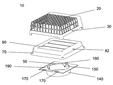
With reference to Figures la and lb, and according to one embodiment of the
present
invention, the pest guard portion of the louvered cover 10 is shown having a
grilled guard
20 which allows for air to exit through the guard 20 and prevent small animals
and
insects from entering a vent emanating from the exterior wall of a building.
The guard 20
also has pin holes 30 which allow for it to be installed onto the louver frame
(not shown)
described with reference to Figures 2a and 2b below.
With reference to Figures 2a and 2b, the louver frame 40 of the present
invention is
shown. The louver frame 40 is generally square in shape and has a square
opening 50 for
the location of louvers (not shown) which can be installed in slots 60. The
louver frame
40 has four securing apertures 70 in order to secure the frame to an outer
wall of a
building, using screws or other securing means. The slots 60 have louver stops
80 which
prevent the louvers 60 from being opened to a position greater than 90 degrees
relative to
the louver frame 40. These louver stops 80 allow for the louvers (not shown)
to be in a
perpendicular relationship with the louver frame 40 when fully deployed by air
exiting
CA 02707953 2010-06-16
the building having a louvered vent cover of the present invention, and in an
almost
parallel relationship with the louver frame 40 when there is no air flow
through the
opening 50. The louver frame 40 also has opposed pins (only one shown, pin 82)
in order
to install the guard 10 onto the louver frame 40. With further reference to
Figure 2a, a
receiving end 84 is positioned at the top end of louver frame 40 in order to
secure an
upper clip present on the vent duct attachment shown in Figures 5a and 5b. One
skilled in
the art would appreciate that the louver frame 40 and accompanying opening 50
may be a
different shape in order to accommodate duct openings of various shapes.
With reference to Figure 3, a louver 90 of the present invention is shown
having a pivot
member 100 and support tabs 110 located at opposite ends of the pivot member
100.
These support tabs 110 are positioned within the slots 60 (as shown in Figures
2a and 2b)
and allow for a louver 90 to either pivot away from the louver frame 40 or
simply rest on
the louver frame 40 when no air is being expelled from the louvered vent cover
of the
present invention.
With reference to Figure 4, the guard 20 is installed on the louver frame 40
by positioning
pin 85 through the pin hole 30 (only one is shown however a corresponding
pin/hole
combination is located on the opposite side).
With reference to Figure 5a and according to one embodiment of the present
invention, a
rear view of the vent duct attachment 120 is shown. The vent duct attachment
120
consists of a frame 130, a pipe mount 140, pipe mount clips 150, and an upper
clip 160.
6
CA 02707953 2010-06-16
The pipe mount 140 fits around the vent duct aperture (not shown), and the
pipe mount
clips 150 provide resistance to removal from the vent duct aperture (not
shown) by
pushing against it. The pipe mount 140 is such a diameter that it creates a
tight fit with
the vent duct aperture (not shown) and does not permit air leakage.
With further reference to Figure 5b and according to one embodiment of the
present
invention, a front view of the vent duct attachment 120 is shown, which shows
the upper
clip 160, as well as lower tabs 170. The upper clip 160 and lower tabs 170 are
intended to
be used for replaceable attachment of the louver frame 40 cover and the vent
duct
attachment, and together form a fastening means to fasten the vent duct
attachment to the
louver frame 40. The upper clip 160 is an extension from the top rear 180 of
the vent duct
attachment 120 which doubles back to project from above the front 190 of the
vent duct
attachment 120. It has a small hook 200 which bends under the end to
positively connect
with a corresponding aperture (not shown) on the rear face of the replaceable
louver
frame 40. The front face 210 of the vent duct attachment 120 is designed to
create a seal
with the replaceable louver frame 40 when it is mounted. In particular, it has
an interface
groove 220 on the perimeter of the front face 210, which facilitates the
formation of a
seal with the louver frame 40.
With reference to Figure 6, and according to one embodiment of the present
invention, an
exploded view of the replaceable louvered cover 10 is shown, which consists of
a pest
guard 20, a louver frame 40 and a vent duct attachment 120. The louver frame
40 is
attached to the vent duct attachment 120 by means of resilient upper clip 160
7
CA 02707953 2010-06-16
interconnecting with receiving end 84 (as shown in Figure 2a) and fixed lower
tabs 170.
The rear face (not shown) of the louver frame 40 has an aperture (not shown)
for
attachment with the upper clip 160, as well as two recessions (not shown) for
engagement
to the lower tabs 170 to create a positive releasable attachment and seal
between the
louver frame 40 and the vent duct attachment 120.
There are two ways in which the vent hood may be used. In the first, on an
installation to
a new home, where no previous vent hood had been attached, the guard 20 is
removed
from the combination, and the vent duct attachment 120 and louver frame 40 are
attached
to one another as described above. The pipe mount 140 is then affixed over the
vent duct
(not shown) by means of the pipe mount clips 150, and some caulking or other
sealing
agent. Securing means such as screws are used in conjunction with the securing
apertures
70 to fasten the vent duct attachment to the side of the building, after which
it may be
sealed to the exterior wall of the building using caulking or another sealing
agent. The
guard 20 is then placed over the vent duct attachment 120, where it snaps into
place by
means of the pins 85 and pin holes 30. The guard 20 may later be removed from
louver
frame 40, and replaced or cleaned. The louver frame 40 may also be replaced
without the
need to remove the vent duct attachment 120; it may be detached by means of
disengaging upper clip 160. When a new louver frame 40 has been obtained, it
is simply
clipped on to the vent duct attachment 120 using the upper clip 160 and lower
tabs 170.
In the second way of using the invention, a vent cover that has been
previously installed
may be broken or leaking air, in that the louvers or flaps are broken or the
frame is
8
CA 02707953 2010-06-16
cracked, and may therefore require replacement. The invention may be installed
over the
existing vent cover, and thereby provide the benefits of the vent cover
without
necessitating the removal of the old cover, which may result in disturbance of
the vent
ducting within the walls of the building. First, the previous louvers or flaps
are removed
from the vent cover. The louver frame 40 may then be fastened over the
existing vent
cover, with securing means such as screws used to fasten the louver frame 40
to the wall
by means of the apertures 70. The louver frame 40 is designed to be larger
than, and fit
over any pre-existing vent cover, so it easily fits over the old vent cover
and may be
sealed against the wall by means of caulking for example. The vent duct
attachment 120
is discarded when using the invention in this second way.
One skilled in the art would appreciate that the louvered design may be
replaced by
another vent covering, such as a hooded free-flow exhaust, or a clamshell
exhaust, among
other exhaust vent designs, without deviating from the scope of the invention.
Many modifications and other embodiments of the invention will come to the
mind of a
person skilled in the art having the benefit of the teachings presented in the
foregoing
description and associated drawings. Therefore, it is understood that the
invention is not
to be limited to the specific embodiment disclosed, and that modifications and
embodiments are intended to be included within the scope of the appended
claims.
9