Note : Les descriptions sont présentées dans la langue officielle dans laquelle elles ont été soumises.
CA 02714284 2010-08-03
WO 2009/098499 PCT/GB2009/050087
Insulation Apparatus and Method
Field of the Invention
The invention relates to an insulation apparatus, in particular an apparatus
for supporting insulating
materials in buildings. The invention also relates to an insulation system and
a method of insulating
a structure.
Background of the Invention
Insulation is added to buildings to conserve energy by preventing heat loss
through floors, walls,
ceilings and lofts. As well as thermal insulation, buildings may be insulated
to prevent noise.
Common forms of insulating materials include polystyrene, fibreglass, foam,
plastic fibres or natural
fibres. They may come in the form of blocks, boards, rolls, loose fill, foam,
batts etc.
The conventional way to lay insulation, for example under a floor, is to lay
nets across floor joists
and pack insulation between the floor joists. The nets are required to hold
the insulation in place
and prevent it from falling through the space between joists. This method is
time consuming as nets
must first be laid and then sufficient insulation material must be tightly
packed onto the net between
the joists. A disadvantage of this method is that it often leads to
ineffective insulation where the
ends of the insulation material become compressed due to positioning on the
nets.
Another conventional method of laying insulation is to support the insulation
on lats which are
screwed to opposing surfaces on floor joists. Again, attaching the lats and
packing the material onto
1
CA 02714284 2010-08-03
WO 2009/098499 PCT/GB2009/050087
them can be time consuming and this method is sometimes ineffective as it is
possible for the
insulation to fall between floor joists.
A further disadvantage associated with both of the above methods is that pipes
such as water or
heating pipes often run at or below the level of insulation. Insulation may
need to be removed to
insert pipes after the building has been insulated. Also, access to pipes for
maintenance or repair
may be restricted or may require removal of a section of insulation and
support.
It would therefore be desirable to provide an improved insulation support
apparatus.
Summary of the Invention
One aspect of the invention provides apparatus for supporting insulation as
specified in Claim 1.
Another aspect of the invention provides apparatus for supporting insulation
as specified in Claim
17.
Another aspect of the invention provides an insulation system as specified in
Claim 19.
Another aspect of the invention provides a method of insulating a structure as
specified in Claim 21.
Yet another aspect of the invention provides an insulated structure as
specified in Claim 22
Yet another aspect of the invention provides a method of manufacture as
specified in Claim 23.
The invention provides an insulation support apparatus comprising an
insulation holding portion
and at least one supporting flange.
2
CA 02714284 2010-08-03
WO 2009/098499 PCT/GB2009/050087
The apparatus for supporting insulation comprises a base portion, at least one
side wall and at least
one supporting flange.
In an in use position the at least one side wall is substantially
perpendicular to the base portion and
in a storage position the at least one side wall and the at least one
supporting flange are substantially
parallel to the base portion.
Advantageously, the apparatus is biased towards the in use position.
In a preferred embodiment, at least one cut or score line facilitates biasing
of the apparatus towards
the in use position.
Preferably, the apparatus is formed substantially from a double skinned
material.
The double skinned material may comprise a first surface layer and a second
surface layer with
connecting elements between the layers.
In a preferred embodiment, a portion of one surface layer is substantially
weaker than a
corresponding portion of the other surface layer.
Preferably, the apparatus comprises at least one cut or score line in the
first surface layer and at least
one cut or score line in the second surface layer.
Advantageously, the cut or score line forms a pivot point about which the
apparatus is pivotable.
At least one supporting flange may be pivotable towards the at least one side
wall.
At least one side wall may be pivotable towards the base portion.
3
CA 02714284 2010-08-03
WO 2009/098499 PCT/GB2009/050087
In one embodiment the apparatus may also comprise insulating material.
Preferably, the supporting flange or flanges is/are arranged to engage a
structural element of a
building such as a joist or cladding.
In a preferred embodiment, at least one portion of the apparatus is
complementary to a portion of
another apparatus. The apparatus may have an extending portion at one end,
which may be
arranged to engage a receiving portion of an adjacent apparatus when in use.
Advantageously, each flange may include a region complementary to another
flange such that the
apparatus may co-operate with an adjacent support apparatus. Adjacent flanges
may have
overlapping and/or interlocking regions.
Preferably, the insulation holding portion comprises a base and at least one
side wall extending from
at least one flange. The insulation holding portion may be formed of plastic
and/or mesh. The
insulation holding portion may be in the form of a trough.
In a preferred embodiment the support apparatus includes strengthening
elements such as ribs.
The support may be formed of double skinned plastic. The plastic may be
recycled plastic.
Preferably the support and/or the insulation holding portion are substantially
rigid.
The side walls may be foldable towards the base of the insulation holding
portion. The flanges may
be foldable toward the base and/or the sidewalls.
Advantageously, the support apparatus may comprise openings. The openings may
be holes or
open regions in a mesh.
4
CA 02714284 2010-08-03
WO 2009/098499 PCT/GB2009/050087
The openings may be arranged to accommodate pipes such as water pipes or
cables.
Advantageously, the support apparatus may comprise sound deadening elements,
such as one or
more layers of sound deadening materials.
Another aspect of the invention provides an insulation system comprising more
than one apparatus
for supporting insulation.
Advantageously the insulation system is coded such that apparatus is readily
identifiable. Preferably
the system provides easy identification of each apparatus, with or without
insulation, according to its
properties.
In a preferred embodiment the insulation system is colour coded.
Another aspect of the invention provides a method of insulating a structure
such as a building,
comprising the steps of a) engaging at least one supporting flange of an
apparatus for supporting
insulation with a structural element of a building and b) securing the
apparatus to the structural
element of a building.
Yet another aspect of the invention provides an insulated structure comprising
structural elements,
at least one support apparatus and insulating material.
An aspect of the invention may provide apparatus for supporting insulation
comprising a base
portion and at least one side wall, wherein in an in use position the at least
one side wall is
substantially perpendicular to the base portion and in a storage position the
at least one side wall is
parallel to the base portion and wherein the apparatus is formed substantially
from double skinned
material.
CA 02714284 2010-08-03
WO 2009/098499 PCT/GB2009/050087
A portion of one surface layer of the double skinned material is preferably
substantially weaker than
a corresponding portion of the other surface layer.
Yet another aspect of the invention may provide a method of manufacture of
apparatus for
supporting insulation comprising the steps of:
i) cutting or scoring a first surface of a double skinned material to define a
supporting
flange portion
ii) cutting or scoring a second surface of a double skinned material to define
a side wall
portion and base portion.
Brief Description of the Drawings
Figure 1 a shows a schematic representation of one embodiment of the invention
Figure 1b shows a side view of the invention of Figure 1 a
Figure 2a shows a side view of the invention of Figure 1 a.
Figure 2b shows a side view of the invention of Figure 1 a.
Figure 3a shows a schematic representation of the invention of Figure 1a.
Figure 3b shows a schematic representation the invention of Figure 1a.
Figure 3c shows a schematic representation of the invention of Figure la.
Figure 4 shows an alternative embodiment of the invention.
Figure 5 shows an alternative embodiment of the invention.
6
CA 02714284 2010-08-03
WO 2009/098499 PCT/GB2009/050087
Detailed Description of the Preferred Embodiments
As shown in Figures 1a and lb, an insulation support 1 comprises flanges 2 and
troughs 3. The
flanges 2 may be stapled or nailed into position on joists 4 or studding in
floors, walls and ceilings.
Insulation material 5 is supported within the troughs 3. In the embodiment
shown in Figure 1, the
apparatus comprises eight troughs. However, the number of troughs maybe
varied. In an
alternative embodiment the insulation support 1 may have a single trough 3.
In a preferred embodiment, each trough 3 has ribs moulded into it for
strength. The base of the
troughs 3 may be solid or may include mesh or other openings to allow the
insulation material to
breathe. The mesh region may be a plastic type mesh arrangement or, for
example, netting material.
Similarly, the walls of the troughs 3 may be solid or include openings as
different types of insulation
have different properties and requirements.
The insulation support 1 may also include holes for electrical cables or water
pipes.
The insulation support 1 is preferably made of plastic. Different grades of
plastic may be selected
according to the particular intended application of the support. In a
preferred embodiment, the
insulation support 1 is made of double skinned plastic, with an air gap
between inner and outer
layers of plastic. A suitable material is fluted polypropylene.
Insulation supports 1 may be coded for different sizes or applications, such
that they are readily
identifiable. For example, insulation supports may be colour coded so that
those for use with floors
are blue and those for use with walls are coloured brown.
7
CA 02714284 2010-08-03
WO 2009/098499 PCT/GB2009/050087
In a preferred embodiment, each support is around one metre in length.
Because floor joists may be spaced at different distances in different
buildings and insulation
requirements may vary according to the area of type of insulation material,
the width and depth of
the supports 1 may be varied.
In use, insulation material 5 is packed into the troughs 3 after supports 1
have been secured in place
on joists or wall studding. This means that insulation can be laid very
quickly because there is no
need to screw additional supports to the joists. The supports, which are
preferably around 1m long,
can simply be laid between joists and stapled in place. In this way a large
area can be covered very
quickly.
Alternatively, the support 1 and insulation 5 may be a ready-made unit that
can be applied to floors,
walls or ceilings in a single step. This means that insulation supports and
insulation may be laid
directly onto joists simultaneously.
The insulation 5 is packed tightly against the walls of the troughs 3, which
secures it in position.
Figure 2a shows a side view of a number of supports 1a, 1b, 1c and 1d, holding
insulation 5 between
floor joists 4. Flooring 6 such as wooden flooring is laid over the floor
joists 4.
This arrangement is beneficial because if work needs to be carried out after
insulation and/or
flooring has been laid, the flooring and/or supports 1 in a particular region
can be removed and
replaced without affecting insulation under the rest of the floor. If pipes or
cables need to be laid in
8
CA 02714284 2010-08-03
WO 2009/098499 PCT/GB2009/050087
a section of the insulation layer, the supports 1 can be removed and holes can
be drilled in the
necessary parts of the supports.
The supports 1 may have holes pre-drilled in them.
The supports 1 are arranged in rows between floor joists 4. As illustrated in
Figure 2b, the flanges 2
cover substantially the entire width of the joists 4 and flanges 2 of supports
in adjacent rows overlap.
In a preferred embodiment each flange 2 is around 50mm wide.
Figures 3a and 3b show two adjacent supports 1' and 1" in the same row. They
are positioned
between two joists 4.
The adjacent ends of the supports 1 in the same row are shaped such that they
fit together. At one
end of support 1', an extending portion 7 is arranged to overlap a receiving
portion 8 at the end of
the adjacent support 1". The length of the extending portion 7 and hence the
region of overlap with
the receiving portion 8 is preferably around 50mm.
These complementary flanges 2 and extending/receiving portions 7,8 make laying
the supports in
the correct positions easier and ensures that insulation material is evenly
distributed. Adjacent
flanges 2 may be overlapping and/or interlocking. Similarly, adjacent
extending portions 7 and
receiving portions 8 may be shaped such that they overlap and/or interlock.
The supports 1 may be stackable for storage and the flanges 2 may cooperate in
the stacked position
to strengthen a stack of supports 1.
Sound insulating or sound deadening materials (not shown) may be added to one
or more sides of
the supports 1. This could be applied using sound deadening adhesive tape. In
a preferred
9
CA 02714284 2010-08-03
WO 2009/098499 PCT/GB2009/050087
embodiment sound deadening materials are applied to the base of the trough 3
and to one of the
flanges 2.
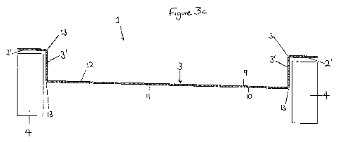
As shown in Figure 3c, the support 1 is formed from a double skinned material,
such as double
skinned plastic. This has an inner layer 9 and an outer layer 10. An air gap
11 between the layers of
plastic provides additional insulation and the double skinned material is
strong such that the support
1 will not bend under the weight of insulating material. Extra support and
strength is provided by
ribs 12 between the layers 9 and 10. The material provides improved rigidity
over single layer
materials.
The support may be cut or scored to allow folding. Preferably a cut is made in
one of the layers 9 or
at points 13 shown in Figure 3c. This allows the support 1 to be folded for
storage, such that the
side walls 3' of each trough may be laid flat against the base of the trough 3
and each of the surfaces
2' of the flanges 2 may be folded down flat against the side walls 3'. This
allows supports 1 to be
stacked substantially flat against each other when stored. Alternatively, the
supports may be
stackable in an in use position or in a partially folded position.
When a support 1 is removed from the flat pack storage position, it is biased
such that it assumes
the configuration shown in Figure 3c in which it is ready for use. The double
skinned material and
score lines or cuts facilitate a "pop up" action into an in use position when
a support is removed
from storage. A cut or score in one surface of the double skinned material
weakens it to allow
contraction of material about a corresponding point in the opposite surface,
which causes the
support to assume the "in use" configuration shown in Figure 3c.
The cut or score line causes a weakening at a point in one layer of the double
skinned material so
that the material about the corresponding point in the opposite surface is of
greater strength. In
alternative embodiments, the weakening or strengthening of areas of the double
skinned material
CA 02714284 2010-08-03
WO 2009/098499 PCT/GB2009/050087
may be created by means other that cuts or score lines, for example, by
stamping the material.
Furthermore, the cuts or score lines may not be continuous cuts or scores
along the material.
The cut or score line may run parallel to the grain in the plastic sheets.
However, this could cause
problems during the manufacturing process, since if the cut or score is not
precisely parallel and cuts
across more than one grain in the plastic, the ability of the sheet to fold
may be affected. This may
be overcome by manufacturing the supports 1 by cutting or scoring in a
direction perpendicular to
the grain of the plastic sheet.
The double skinned plastic provides benefits for acoustic insulation. At the
floor joists, flanges 2 of
adjacent supports 1 over lap, providing two air gaps 10 in double skinned
layers under the floor
boards. Because the air gap 10 has insulating properties, less insulation
material may need to be
added to the trough 3.
The support 1 may be made using recycled plastic material. The flanges 2 may
include indicia to
show a user where to attach it to joists.
Depending on the building methods used in particular countries, it may be
preferable to fit the
insulation supports from below the joists 4. As illustrated in Figure 5, the
support 1 may be attached
to a joist with flanges 2 on the top surfaces of the joist, or may be attached
such that the surfaces 2'
of the flanges 2 are attached to the lower surfaces of joists and insulation
may be packed into the
trough and/or on top of the underside of the trough 3, between the joists, as
shown in Figure 5.
Figure 4 shows an alternative embodiment of the invention in which the trough
3 of the support 1
has partial wall or base elements 3'.
11
CA 02714284 2010-08-03
WO 2009/098499 PCT/GB2009/050087
In an alternative embodiment the supporting flanges 2 may be formed separately
from the trough 3.
The flanges 2 may be in the form of hooks or clips that attach to the joists
and the side walls of the
troughs 3.
12