Sélection de la langue

Search

Sommaire du brevet 2718329 

Énoncé de désistement de responsabilité concernant l'information provenant de tiers

Une partie des informations de ce site Web a été fournie par des sources externes. Le gouvernement du Canada n'assume aucune responsabilité concernant la précision, l'actualité ou la fiabilité des informations fournies par les sources externes. Les utilisateurs qui désirent employer cette information devraient consulter directement la source des informations. Le contenu fourni par les sources externes n'est pas assujetti aux exigences sur les langues officielles, la protection des renseignements personnels et l'accessibilité.

Disponibilité de l'Abrégé et des Revendications

L'apparition de différences dans le texte et l'image des Revendications et de l'Abrégé dépend du moment auquel le document est publié. Les textes des Revendications et de l'Abrégé sont affichés :

  • lorsque la demande peut être examinée par le public;
  • lorsque le brevet est émis (délivrance).
(12) Brevet: (11) CA 2718329
(54) Titre français: BOITIER DE CONNEXION POUR COMMUTATEUR CENTRIFUGE D'UN MOTEUR ET MOTEUR UTILISANT CELUI-CI
(54) Titre anglais: TERMINAL BOX FOR CENTRIFUGAL SWITCH OF MOTOR AND MOTOR USING THE SAME
Statut: Octroyé
Données bibliographiques
(51) Classification internationale des brevets (CIB):
  • H02K 5/22 (2006.01)
  • H02K 11/23 (2016.01)
(72) Inventeurs :
  • CHEN, FUCHENG (Chine)
  • LU, PING (Chine)
  • DENG, SHUANGCHAO (Chine)
  • LIU, XIAO (Chine)
(73) Titulaires :
  • ZHONGSHAN BROAD-OCEAN MOTOR MANUFACTURING CO., LTD. (Chine)
(71) Demandeurs :
  • ZHONGSHAN BROAD-OCEAN MOTOR MANUFACTURING CO., LTD. (Chine)
(74) Agent:
(74) Co-agent:
(45) Délivré: 2017-10-17
(22) Date de dépôt: 2010-10-22
(41) Mise à la disponibilité du public: 2011-09-25
Requête d'examen: 2014-03-20
Licence disponible: S.O.
(25) Langue des documents déposés: Anglais

Traité de coopération en matière de brevets (PCT): Non

(30) Données de priorité de la demande:
Numéro de la demande Pays / territoire Date
211020148430.5 Chine 2010-03-25

Abrégés

Abrégé français

Linvention révèle un boîtier de connexion de commutateur centrifuge dun moteur et un moteur comportant ledit boîtier. Le boîtier de connexion comprend un boîtier (51), une tige de commande mobile (7) disposée sur le boîtier (51) et se prolongeant partiellement du boîtier, plusieurs contacts électriques (8) disposés dans le boîtier (51) et un thermostat (9) disposé sur une surface dextrémité du boîtier, le boîtier (51) comportant une pièce de réception (10) fonctionnant pour recevoir le thermostat (9), une extrémité du contact électrique (8) se prolongeant du boîtier et formant une pièce de connexion (81), une plaque de séparation (11) étant disposée entre la pièce de connexion (81) et le thermostat (9). Le boîtier de connexion comporte également un mécanisme de câblage (12), une extrémité du mécanisme de câblage (12) est connectée à la pièce de connexion (81) et lautre extrémité contourne lextérieur de la plaque de séparation (11) et est connectée à une borne (91) du thermostat. Si le thermostat présente une défaillance de détection de température, les utilisateurs du moteur peuvent facilement retirer le mécanisme de câblage et mettre hors tension opportune une alimentation connectée au moteur par un circuit de protection externe, empêchant ainsi le moteur de griller.


Abrégé anglais

The invention discloses a terminal box for a centrifugal switch of a motor and a motor using the same. The terminal box includes a box (51), a movable control rod (7) disposed on the box (51) and partially extending from the box, multiple electric contacts (8) disposed in the box (51), and a thermostat (9) disposed on end surface of the box, the box (51) having a receiving part (10) operating to receive the thermostat (9), one end of the electric contact (8) extending from the box and forming a connecting part (81), a separating plate (11) being disposed between the connecting part (81) and the thermostat (9). The terminal box further includes a wiring mechanism (12), one end of the wiring mechanism (12) is connected to the connecting part (81), and the other end thereof bypasses the outside of the separating plate (11) and is connected to a terminal (91) of the thermostat. If the thermostat has temperature detection failure, users of the motor can easily remove the wiring mechanism, and timely switch off a power supply connected to the motor via an external protection circuit whereby preventing the motor from being burned out.

Revendications

Note : Les revendications sont présentées dans la langue officielle dans laquelle elles ont été soumises.


CLAIMS
1. A terminal box for a centrifugal connector of a motor, comprising a box
(51), a
movable control rod (7) disposed on said box (51) and extending from said box
(51), an electric contact (8) disposed in said box (51), and a thermostat (9)
disposed on an end surface of said box (51), said box (51) comprising a
receiving
part (10) operating to receive said thermostat (9), one end of said electric
contact
(8) extending from said box and forming a connecting part (81), a separating
plate
(11) being disposed between said connecting part (81) and said thermostat (9);
wherein
said terminal box further comprises a connector (12);
one end of said connector (12) is connected to said connecting part (81);
the other end connector (12) bypasses the outside of said separating plate
(11) and is connected to a terminal (91) of said thermostat;
said connector (12) comprises a first connecting terminal (121) connected
to said connecting part (81), a second connecting terminal (122) connected to
said
terminal (91), and an electrical lead (123);
one end of said electrical lead (123) is connected to said first connecting
terminal (121); and
the other end of said electical lead (123) bypasses the outside of said
separating plate (11) and is connected to said second connecting terminal
(122).
2. The terminal box of claim 1, wherein
said first connecting terminal (121) comprises a first pressing part and a
first inserting part connected to said first pressing part;
said first pressing part presses and penetrates a surface of said electrical
lead (123);
8

said first inserting part is directly connected to said terminal (91) and said

connecting part (81);
said second connecting terminal (122) comprises a second pressing part
and a second inserting part connected to said second pressing part;
said second pressing part presses and penetrates a surface of said electrical
lead (123); and
said second inserting part is directly connected to said terminal (91) and
said connecting part (81).
3. A motor, comprising said terminal box of claim 1, a stator (1), a rotor
(2), a front
end cover (3), and a rear end cover (4), said front end cover (3) being
connected
to said rear end cover (4) thereby forming a cavity (6), said rotor (2) and
said
stator (1) being disposed in said cavity (6), and said terminal box (5) being
disposed on outer wall of said front end cover (3) or said rear end cover (4).
4. The motor of claim 3, wherein
a fixing part (14) is disposed on said outer wall of said front end cover (3)
or said rear end cover (4) and in the vicinity of said terminal box (5);
said fixing part (14) comprises a fixing clamp (15);
said fixing clamp (15) fixes an enameled wire (13) led out from said
motor; and
a tail of said enameled wire (13) is disposed in said terminal box (5).
5. The motor of claim 3, wherein
said first connecting terminal (121) comprises a first pressing part and a
first inserting part connected to said first pressing part;
9

said first pressing part presses and penetrates a surface of said electrical
lead (123);
said first inserting part is directly connected to said terminal (91) and said

connecting part (81);
said second connecting terminal (122) comprises a second pressing part
and a second inserting part connected to said second pressing part;
said second pressing part presses and penetrates a surface of said electrical
lead (123); and
said second inserting part is directly connected to said terminal (91) and
said connecting part (81).

6. The motor of claim 5, wherein
said first connecting terminal (121) is integrally formed via aluminum; and
said second connecting terminal (122) is integrally fanned via aluminum.


Description

Note : Les descriptions sont présentées dans la langue officielle dans laquelle elles ont été soumises.


CA 02718329 2010-10-22

TERMINAL BOX FOR CENTRIFUGAL SWITCH OF MOTOR AND MOTOR
USING THE SAME

FIELD OF THE INVENTION

[0001] The invention relates to a terminal box for a centrifugal switch of a
motor and a motor using the same.

BACKGROUND OF THE INVENTION

[0002] Nowadays, most terminal boxes for centrifugals switches of
single-phase induction motors each comprise a box, a movable control rod
extending from the box, and a thermostat disposed on end surface of the box. A
function of the thermostat is to measure a temperature between the stator and
the
rotor as overloading occurs on the single-phase induction motor, and to switch
off
a power supply connected to the motor as temperature is too high. As shown in

FIG. 1, a box comprises a receiving part 3 operating to receive the thermostat
2,
and multiple connecting terminals 4. An electric connection sheet 5 is
extended
from the top of the connecting terminal 4, a separating plate 6 is disposed
between the connecting terminal 4 and the thermostat 2, a groove 7 is disposed
on the separating plate 6, the electric connection sheet 5 passes through the

groove 7 and is spot-welded with a terminal 8 of the thermostat. This
structure has
the following problems: since the electric connection sheet is spot-welded
with the
terminal of the thermostat, as the thermostat has temperature detection
failure, it
is impossible to timely switch off the power supply connected to the motor,
and the
motor will be burned out, which brings great trouble for users of the motor.

Moreover, it is difficult and inconvenient for the users to remove the
electric
connection sheet.

1


CA 02718329 2010-10-22
SUMMARY OF THE INVENTION

[0003] It is one objective of the invention to provide a terminal box for a
centrifugal switch of a motor that is capable of addressing the above-
mentioned
problems, and features simple structure of a wiring mechanism, and convenient

assembling and disassembling, and brings great convenience for users of the
motor.

[0004] The invention is implemented as follows:

[0005] A terminal box for a centrifugal switch of a motor, comprising a box, a
movable control rod disposed on the box and partially extending from the box,
multiple electric contacts disposed in the box, and a thermostat disposed on
end
surface of the box, the box comprising a receiving part operating to receive
the
thermostat, one end of the electric contact extending from the box and forming
a
connecting part, a separating plate being disposed between the connecting part

and the thermostat. The terminal box further comprises a wiring mechanism, one
end of the wiring mechanism is connected to the connecting part, and the other
end thereof bypasses the outside of the separating plate and is connected to a
terminal of the thermostat.

[0006] The wiring mechanism comprises a first connecting terminal connected
to the connecting part, a second connecting terminal connected to the
terminal,
and an electrical lead, one end of the electrical lead is connected to the
first
connecting terminal, and the other end thereof bypasses the outside of the
separating plate and connected to the second connecting terminal.

[0007] The connecting terminals each comprises a pressing part, and an
inserting part connected to the pressing part, the pressing part presses and
punctuates surface of the electrical lead, and the inserting part is directly
2


CA 02718329 2010-10-22

connected to the terminal and the connecting part.

[0008] Advantage of the invention comprises: the wiring mechanism features
simple structure, and convenient disassembling and assembling, which brings
great convenience for users of the motor; even the thermostat has temperature

detection failure, the users can easily remove the wiring mechanism, and
timely
switch off the power supply connected to the motor via an external protection
circuit, whereby preventing the motor from being burned out.

[0009] It is another objective of the invention to provide a motor that is
capable
of addressing the above-mentioned problems and comprising a wiring mechanism
in a terminal box thereof, and features simple structure of a wiring
mechanism,

and convenient assembling and disassembling, brings great convenience for
users of the motor, and prevents the motor from being burned out.

[0010] The invention is implemented as follows:

[0011] A motor, comprising a stator, a rotor, a front end cover, a rear end
cover,
and a terminal box, the front end cover being connected to the rear end cover
whereby forming a cavity, the rotor and the stator being disposed in the
cavity, the
terminal box being disposed on outer wall of one of the end covers, the
terminal
box comprising a box, a movable control rod disposed on the box and partially
extending from the box, multiple electric contacts disposed in the box, and a

thermostat disposed on end surface of the box, the box comprising a receiving
part operating to receive the thermostat, one end of the electric contact
extending
from the box and forming a connecting part, a separating plate being disposed
between the connecting part and the thermostat. The terminal box further
comprises a wiring mechanism, one end of the wiring mechanism is connected to

the connecting part, and the other end thereof bypasses the outside of the
separating plate and is connected to a terminal of the thermostat.

3


CA 02718329 2010-10-22

[0012] A fixing part is disposed on outer wall of the end cover and in the
vicinity
of the terminal box, the fixing part comprises a fixing clamp, the fixing
clamp fixes
an enameled wire led out from the motor, and a tail of the enameled wire is
disposed in the terminal box.

[0013] The wiring mechanism comprises a first connecting terminal connected
to the connecting part, a second connecting terminal connected to the
terminal,
and an electrical lead, one end of the electrical lead is connected to the
first
connecting terminal, and the other end thereof bypasses the outside of the
separating plate and connected to the second connecting terminal.

[0014] The connecting terminals each comprises a pressing part, and an
inserting part connected to the pressing part, the pressing part presses and
punctuates surface of the electrical lead, and the inserting part is directly
connected to the terminal and the connecting part.

[0015] The connecting terminal is integrally formed via aluminum.

[0016] Advantages of the invention comprise: 1) the wiring mechanism
features simple structure, and convenient disassembling and assembling, which
brings great convenience for users of the motor; even the thermostat has
temperature detection failure, the users can easily remove the wiring
mechanism,
and timely switch off the power supply connected to the motor via an external

protection circuit, whereby preventing the motor from being burned out; 2) the
fixing part is disposed on the motor, the fixing clamp on the fixing part
effectively
protects and fixes the enameled wire led out from the motor, and ensures
stability
and reliability of electric connection.

BRIEF DESCRIPTION OF THE DRAWINGS

[0017] FIG. 1 is a solid diagram of a terminal box for a centrifugal switch of
a
4


CA 02718329 2010-10-22
motor in the related art;

[0018] FIG. 2 is a solid diagram of a terminal box for a centrifugal switch of
a
motor of an exemplary embodiment of the invention;

[0019] FIG. 3 is a partially exploded view of FIG. 2;

[0020] FIG. 4 is an internal structural view of a terminal box in FIG. 2
without a
bottom cover;

[0021] FIG. 5 illustrates connection between an electrical lead and a
connecting terminal in FIG. 3;

[0022] FIG. 6 is a cross-sectional view of connection between the electrical
lead and the connecting terminal in FIG. 5;

[0023] FIG. 7 is a solid diagram of a motor of another exemplary embodiment
of the invention; and

[0024] FIG. 8 is an enlarged view of FIG. 7 along an A-A line.
DETAILED DESCRIPTION OF THE EMBODIMENTS

[0025] Further description of the invention will be given below in conjunction
with specific embodiments and accompanying drawings.

[0026] Embodiment 1

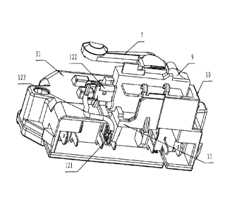
[0027] As shown in FIGS. 2, 3 and 4, a terminal box for a centrifugal switch
of
a motor comprises a box 51, a movable control rod 7 disposed on the box 51 and
partially extending from the box, multiple electric contacts 8 disposed in the
box
51, and a thermostat 9 disposed on end surface of the box. The box 51
comprises
a receiving part 10 operating to receive the thermostat 9, one end of the
electric
contact 8 extending from the box and forming a connecting part 81, a
separating
5


CA 02718329 2010-10-22

plate 11 being disposed between the connecting part 81 and the thermostat 9.
The terminal box further comprises a wiring mechanism 12, one end of the
wiring
mechanism 12 is connected to the connecting part 81, and the other end thereof
bypasses the outside of the separating plate 11 and is connected to a terminal
91
of the thermostat.

[0028] The wiring mechanism 12 comprises a first connecting terminal 121
connected to the connecting part 81, a second connecting terminal 122
connected
to the terminal 91, and an electrical lead 123. One end of the electrical lead
123 is
connected to the first connecting terminal 121, and the other end thereof

bypasses the outside of the separating plate 11 and connected to the second
connecting terminal 122. As shown in FIGS. 5 and 6, the connecting terminals
each comprises a pressing part 124, and an inserting part 125 connected to the
pressing part 124. The pressing part 124 presses and punctuates surface of the
electrical lead 123, and the inserting part 125 is directly connected to the
terminal

91 and the connecting part 81, whereby forming electric connection between the
thermostat and the connecting part 81 of the electric contact 8.

[0029] Embodiment 2

[0030] As shown in FIG. 7, a motor of the invention comprises a stator 1, a
rotor 2, a front end cover 3, a rear end cover 4, and a terminal box 5. The
front
end cover 3 is connected to the rear end cover 4 whereby forming a cavity 6,
the

rotor 2 and the stator 1 are disposed in the cavity 6, and the terminal box 5
is
disposed on outer wall of one of the end covers. As shown in FIGS. 2, 3 and 4,
the
terminal box 5 comprises a box 51, a movable control rod 7 disposed on the box
51 and partially extending from the box, multiple electric contacts 8 disposed
in

the box 51, and a thermostat 9 disposed on end surface of the box. The box 51
comprises a receiving part 10 operating to receive the thermostat 9, one end
of
the electric contact 8 extending from the box and forming a connecting part
81, a
6


CA 02718329 2010-10-22

separating plate 11 is disposed between the connecting part 81 and the
thermostat 9. The terminal box further comprises a wiring mechanism 12, one
end
of the wiring mechanism 12 is connected to the connecting part 81, and the
other
end thereof bypasses the outside of the separating plate 11 and is connected
to a
terminal 91 of the thermostat.

[0031] As shown in FIG. 8, a fixing part 14 is disposed on outer wall of the
end
cover and in the vicinity of the terminal box 5, the fixing part 14 comprises
a fixing
clamp 15, the fixing clamp 15 fixes an enameled wire 13 led out from the
motor;
and a tail of the enameled wire 13 is disposed in the terminal box 5 whereby
forming electric connection.

[0032] As shown in FIGS. 2, 3 and 4, the wiring mechanism 12 comprises a
first connecting terminal 121 connected to the connecting part 81, a second
connecting terminal 122 connected to the terminal 91, and an electrical lead
123,
one end of the electrical lead 123 is connected to the first connecting
terminal 121,

and the other end thereof bypasses the outside of the separating plate 11 and
connected to the second connecting terminal 122. As shown in FIGS. 5 and 6,
the
connecting terminals each comprises a pressing part 124, and an inserting part
125 connected to the pressing part 124, the pressing part 124 presses and
punctuates surface of the electrical lead 123, and the inserting part 125 is
directly

connected to the terminal 91 and the connecting part 81 whereby forming
electric
connection between the thermostat and the connecting part 81 of the electric
contact 8.

[0033] Each of the connecting terminals is integrally formed via aluminum, the
pressing part 124 and the inserting part 125 thereof are formed by bending two
symmetric plates, and the pressing part 124 and the inserting part 125 are
approximately B-shaped.

7

Dessin représentatif
Une figure unique qui représente un dessin illustrant l'invention.
États administratifs

Pour une meilleure compréhension de l'état de la demande ou brevet qui figure sur cette page, la rubrique Mise en garde , et les descriptions de Brevet , États administratifs , Taxes périodiques et Historique des paiements devraient être consultées.

États administratifs

Titre Date
Date de délivrance prévu 2017-10-17
(22) Dépôt 2010-10-22
(41) Mise à la disponibilité du public 2011-09-25
Requête d'examen 2014-03-20
(45) Délivré 2017-10-17

Historique d'abandonnement

Il n'y a pas d'historique d'abandonnement

Taxes périodiques

Dernier paiement au montant de 263,14 $ a été reçu le 2023-09-12


 Montants des taxes pour le maintien en état à venir

Description Date Montant
Prochain paiement si taxe générale 2024-10-22 347,00 $
Prochain paiement si taxe applicable aux petites entités 2024-10-22 125,00 $

Avis : Si le paiement en totalité n'a pas été reçu au plus tard à la date indiquée, une taxe supplémentaire peut être imposée, soit une des taxes suivantes :

  • taxe de rétablissement ;
  • taxe pour paiement en souffrance ; ou
  • taxe additionnelle pour le renversement d'une péremption réputée.

Les taxes sur les brevets sont ajustées au 1er janvier de chaque année. Les montants ci-dessus sont les montants actuels s'ils sont reçus au plus tard le 31 décembre de l'année en cours.
Veuillez vous référer à la page web des taxes sur les brevets de l'OPIC pour voir tous les montants actuels des taxes.

Historique des paiements

Type de taxes Anniversaire Échéance Montant payé Date payée
Le dépôt d'une demande de brevet 400,00 $ 2010-10-22
Taxe de maintien en état - Demande - nouvelle loi 2 2012-10-22 100,00 $ 2012-08-27
Taxe de maintien en état - Demande - nouvelle loi 3 2013-10-22 100,00 $ 2013-09-30
Requête d'examen 800,00 $ 2014-03-20
Taxe de maintien en état - Demande - nouvelle loi 4 2014-10-22 100,00 $ 2014-10-14
Taxe de maintien en état - Demande - nouvelle loi 5 2015-10-22 200,00 $ 2015-10-22
Taxe de maintien en état - Demande - nouvelle loi 6 2016-10-24 200,00 $ 2016-10-20
Taxe finale 300,00 $ 2017-08-30
Taxe de maintien en état - brevet - nouvelle loi 7 2017-10-23 200,00 $ 2017-10-23
Taxe de maintien en état - brevet - nouvelle loi 8 2018-10-22 200,00 $ 2018-10-22
Taxe de maintien en état - brevet - nouvelle loi 9 2019-10-22 200,00 $ 2019-10-15
Taxe de maintien en état - brevet - nouvelle loi 10 2020-10-22 250,00 $ 2020-08-11
Taxe de maintien en état - brevet - nouvelle loi 11 2021-10-22 255,00 $ 2021-09-24
Taxe de maintien en état - brevet - nouvelle loi 12 2022-10-24 254,49 $ 2022-07-18
Taxe de maintien en état - brevet - nouvelle loi 13 2023-10-23 263,14 $ 2023-09-12
Titulaires au dossier

Les titulaires actuels et antérieures au dossier sont affichés en ordre alphabétique.

Titulaires actuels au dossier
ZHONGSHAN BROAD-OCEAN MOTOR MANUFACTURING CO., LTD.
Titulaires antérieures au dossier
S.O.
Les propriétaires antérieurs qui ne figurent pas dans la liste des « Propriétaires au dossier » apparaîtront dans d'autres documents au dossier.
Documents

Pour visionner les fichiers sélectionnés, entrer le code reCAPTCHA :


Pour visualiser une image, cliquer sur un lien dans la colonne description du document. Pour télécharger l'image (les images), cliquer l'une ou plusieurs cases à cocher dans la première colonne et ensuite cliquer sur le bouton "Télécharger sélection en format PDF (archive Zip)" ou le bouton "Télécharger sélection (en un fichier PDF fusionné)".

Liste des documents de brevet publiés et non publiés sur la BDBC .

Si vous avez des difficultés à accéder au contenu, veuillez communiquer avec le Centre de services à la clientèle au 1-866-997-1936, ou envoyer un courriel au Centre de service à la clientèle de l'OPIC.


Description du
Document 
Date
(yyyy-mm-dd) 
Nombre de pages   Taille de l'image (Ko) 
Description 2010-10-22 7 286
Abrégé 2010-10-22 1 27
Revendications 2010-10-22 4 101
Dessins 2010-10-22 8 181
Dessins représentatifs 2011-09-07 1 20
Page couverture 2011-09-13 2 64
Revendications 2016-02-29 3 92
Revendications 2017-02-08 3 84
Dessins 2017-02-08 8 181
Cession 2010-10-22 4 90
Taxe finale 2017-08-30 2 54
Dessins représentatifs 2017-09-14 1 14
Page couverture 2017-09-14 1 52
Paiement de taxe périodique 2017-10-23 2 57
Paiement de taxe périodique 2018-10-22 2 55
Correspondance 2010-11-10 1 27
Correspondance 2011-05-04 4 128
Paiement de taxe périodique 2016-10-20 2 55
Taxes 2012-08-27 3 94
Paiement de taxe périodique 2019-10-15 2 55
Taxes 2013-09-30 2 61
Poursuite-Amendment 2014-06-23 5 173
Poursuite-Amendment 2014-03-20 4 120
Taxes 2014-10-14 2 62
Demande d'examen 2015-09-01 3 220
Paiement de taxe périodique 2015-10-22 2 54
Modification 2016-02-29 14 398
Demande d'examen 2016-08-08 4 207
Modification 2017-02-08 12 394