Sélection de la langue

Search

Sommaire du brevet 2718643 

Énoncé de désistement de responsabilité concernant l'information provenant de tiers

Une partie des informations de ce site Web a été fournie par des sources externes. Le gouvernement du Canada n'assume aucune responsabilité concernant la précision, l'actualité ou la fiabilité des informations fournies par les sources externes. Les utilisateurs qui désirent employer cette information devraient consulter directement la source des informations. Le contenu fourni par les sources externes n'est pas assujetti aux exigences sur les langues officielles, la protection des renseignements personnels et l'accessibilité.

Disponibilité de l'Abrégé et des Revendications

L'apparition de différences dans le texte et l'image des Revendications et de l'Abrégé dépend du moment auquel le document est publié. Les textes des Revendications et de l'Abrégé sont affichés :

  • lorsque la demande peut être examinée par le public;
  • lorsque le brevet est émis (délivrance).
(12) Brevet: (11) CA 2718643
(54) Titre français: PORTE OUTIL A MAIN
(54) Titre anglais: HAND TOOL HOLDER
Statut: Octroyé
Données bibliographiques
(51) Classification internationale des brevets (CIB):
  • B25H 3/04 (2006.01)
  • A47F 5/08 (2006.01)
  • A47G 29/02 (2006.01)
  • B25H 3/00 (2006.01)
(72) Inventeurs :
  • KAO, JUI-CHIEN (Taïwan, Province de Chine)
(73) Titulaires :
  • KAO, JUI-CHIEN (Chine)
(71) Demandeurs :
  • KAO, JUI-CHIEN (Chine)
(74) Agent: ADE & COMPANY INC.
(74) Co-agent:
(45) Délivré: 2015-06-09
(22) Date de dépôt: 2010-10-15
(41) Mise à la disponibilité du public: 2012-04-15
Requête d'examen: 2012-10-22
Licence disponible: S.O.
(25) Langue des documents déposés: Anglais

Traité de coopération en matière de brevets (PCT): Non

(30) Données de priorité de la demande: S.O.

Abrégés

Abrégé français

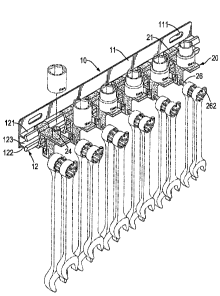
Un porte-outil à main possède une base (10) des éléments de retenue multiples (20). La base (10) possède un siège suspendu (11) et un rail (12). Le rail (12) dépasse du siège suspendu (11). Chaque élément de retenue (20) possède un bloc coulissant (21), une saillie (22), un panneau extensible (23), un embout extensible (24), une monture darbre (25) et un arbre suspendu (26). Le bloc coulissant (21) est monté sur le rail (12). La saillie (22) dépasse du bloc coulissant (21). Le panneau extensible (23) dépasse de la saillie (22). Lembout extensible (24) dépasse du panneau extensible (23). La monture darbre (25) dépasse de la saillie (22) opposée à lembout extensible (24) et possède un bloc inséré (253) situé au bas de la monture darbre (25). Larbre suspendu (26) est en métal, est enveloppé dans le bloc inséré (253) par moulage par injection.


Abrégé anglais

A hand tool holder has a base (10) and multiple holding elements (20). The base (10) has a hanging seat (11) and a track (12). The track (12) protrudes from the hanging seat (11). Each holding element (20) has a sliding block (21), a protrusion (22), an extending board (23), a mounting stub (24), a shaft mount (25) and a hanging shaft (26). The sliding block (21) is mounted on the track (12). The protrusion (22) protrudes from the sliding block (21). The extending board (23) protrudes from the protrusion (22). The mounting stub (24) protrudes from the extending board (23). The shaft mount (25) protrudes from the protrusion (22) opposite to the mounting stub (24) and has an inserted block (253) located on a bottom of the shaft mount (25). The hanging shaft (26) is metal, is wrapped in the inserted block (253) by injection molding.

Revendications

Note : Les revendications sont présentées dans la langue officielle dans laquelle elles ont été soumises.


6

WHAT IS CLAIMED IS:


1. A hand tool holder comprising:
a base having

a hanging seat;

a track protruding from the hanging seat and having
a top surface;

a bottom surface;

a top channel defined in the top surface of the track;

a bottom channel defined in the bottom surface of the
track; and

multiple holding elements and each having

a sliding block slidably mounted on the track and having
a top arm slidably hooked on the top channel;

a bottom arm slidably hooked on the bottom channel;

a protrusion protruding from the sliding block, being opposite to
the track and having an extending surface;

an extending board protruding from the protrusion;

a mounting stub protruding from the extending board;

a shaft mount perpendicularly protruding from the extending
surface of the protrusion, being opposite to the mounting stub and having

a bottom;
two sides;
four ribs;

two recesses respectively defined in the two sides of the


7

shaft mount to form the four ribs respectively at the sides of the shaft
mount;

an inserted block having a round cross section, formed
on the bottom of the shaft mount below the four ribs and the recesses; and

a hanging shaft being metal, wrapped in the inserted block by
injection molding and having

an inserted end wrapped in the inserted block;

a hanging end opposite to the inserted end of the
hanging shaft and protruding from the inserted block;

a flange protruding from the inserted end of the hanging
shaft and wrapped in the inserted block; and

a hook protruded upwardly from the hanging end.


2. The hand tool holder as claimed in claim 1, wherein each protrusion
has a through hole defined through the protrusion.


3. The hand tool holder as claimed in claim 1 or 2, wherein
each extending board is a rectangular board; and

the hanging end of each hanging shaft has an extension length from a
corresponding inserted block longer that of a corresponding extending board
from a corresponding protrusion.


4. The hand tool holder as claimed in claim 3, wherein the hanging seat
is rectangular and has two hanging holes defined through the hanging seat.

Description

Note : Les descriptions sont présentées dans la langue officielle dans laquelle elles ont été soumises.


CA 02718643 2010-10-15
1

1 HAND TOOL HOLDER
2 BACKGROUND OF THE INVENTION

3 1. Field of the Invention

4 The present invention relates to a holder, and more particularly to a hand
tool holder.

6 2. Description of Related Art

7 A hand tool holder can be mounted on a wall with fasteners and has
8 multiple hanging hooks on which multiple wrenches are hanged.

9 However, a conventional hand tool cannot hold a sleeve. Furthermore,
in order to hang a heavily hand tool on the conventional hand tool holder,
sizes
11 of the hanging hooks have to be increasing according to weights of the
wrenches
12 so causing waste of material.

13 To overcome the shortcomings, the present invention tends to provide a
14 hand tool holder to mitigate or obviate the aforementioned problems.

SUMMARY OF THE INVENTION

16 A hand tool holder has a base and multiple holding elements. The base
17 has a hanging seat and a track. The track protrudes from the hanging seat.
Each
18 holding element has a sliding block, a protrusion, an extending board, a
19 mounting stub, a shaft mount and a hanging shaft. The sliding block is
mounted
on the track. The protrusion protrudes from the sliding block. The extending
21 board protrudes from the protrusion. The mounting stub protrudes from the
22 extending board. The shaft mount protrudes from the protrusion, is opposite
to
23 the mounting stub and has an inserted block located on a bottom of the
shaft
24 mount. The hanging shaft is metal, is wrapped in the inserted block by
injection


CA 02718643 2010-10-15
2

1 molding. Therefore, the holding elements is durable in structure to load and
2 support a heavily hand too].

3 Other objects, advantages and novel features of the invention will
4 become more apparent from the following detailed description when taken in
conjunction with the accompanying drawings.

6 BRIEF DESCRIPTION OF THE DRAWINGS

7 Fig. 1 is a partially exploded perspective view of a hand tool holder in
8 accordance with the present invention with tools;

9 Fig. 2 is an enlarged perspective view of a holding element of the hand
tool holder in Fig. 1;

11 Fig. 3 is an enlarged side view in partial section of the hand tool holder
12 in Fig. 1;

13 Fig. 4 is an operational and partially exploded perspective view of the
14 hand tool holder in Fig. 1 with tools being mounted on a ped board;

Fig. 5 is an operational enlarge side view in partial section of the hand
16 tool holder in Fig. 1; and

17 Fig. 6 is an exploded operational perspective view of the hand tool
18 holder in Fig. 1.

19 DETAILED DESCRIPTION OF PREFERRED EMBODIMENT

With reference to Figs. 1 to 3, a hand tool holder in accordance with the
21 present invention comprises a base 10 and multiple holding elements 20. The
22 base 10 has a hanging seat 11 and a track 12. The hanging seat 11 is
rectangular
23 and has two hanging holes 111. The two hanging holes 111 are defined
through
24 the hanging seat 11 and the hand tool holder may be mounted on a wall with
two


CA 02718643 2010-10-15
3

1 fasteners mounted through the hanging holes 1 1 ] . The track 12 protrudes
from
2 along the hanging seat 11 and has a top surface, a bottom surface, an
abutting
3 surface, a top channel 121, a bottom channel 122 and a ditch 123. The
abutting
4 surface is perpendicularly the top surface and the bottom surface. The top
channel 121 is defined in along the top surface of the track 12. The bottom
6 channel 122 is defined in along the bottom surface of the track 12. The
ditch 123
7 is defined in along the abutting surface of the track 12 between the top
surface
8 and the bottom surface to provide a space, so that the top surface of the
track 12
9 and the bottom surface of the track 12 is allowed to be curved.

The holding elements 20 are manufactured by injection molding and
11 each holding element 20 has a sliding block 21, a protrusion 22, an
extending
12 board 23, a mounting stub 24, a shaft mount 25 and a hanging shaft 26. The
13 sliding block 21 is slidably mounted on the track 12 and has a top ann 211
and a
14 bottom arm 212. The top arm 211 slidably hooks in the top channel 121. The
bottom arm 212 slidably hooks in the bottom channel 122. The protrusion 22
16 protrudes from the sliding block 21, is hollow and opposite to the track 12
and
17 has an extending surface and a through hole 221. The through hole 221 is
defined
18 through the protrusion 22. The extending board 23 is a rectangular board
and is
19 formed on and protrudes from the protrusion 22. The mounting stub 24 is a
cylinder and perpendicularly protrudes from the extending board 23. The shaft
21 mount 25 perpendicularly protrudes from the extending surface of the
protrusion
22 22 and is opposite to the mounting stub 24. The extending stub 25 has two
sides,
23 a bottom, two recesses 251, four ribs 252 and an inserted block 253. The
recesses
24 251 are respectively defined in the two sides of the shaft mount 25 to form
the


CA 02718643 2010-10-15
4

1 four ribs 252 respectively at the sides of the shaft mount 25. The inserted
block
2 253 has a round cross section and is formed on the bottom of the shaft mount
25
3 below the four ribs 252 and the recesses 251. The hanging shaft 26 is metal,
is
4 wrapped in the inserted block 253 by injection molding and has an inserted
end,
a hanging end, a flange 261 and a hook 262. The inserted end of the hanging
6 shaft 26 is inserted the inserted block 253. The hanging end of the hanging
shaft
7 26 is opposite to the inserted end of the hanging shaft 26, protrudes from
the
8 inserted block 253 and having an extension length from the inserted block
253
9 longer that of the extending board 23 from the protrusion 22. The flange 261
is
square in cross section, protrusions from the inserted end of the hanging
shaft 26
11 and is wrapped in the inserted block 253, so the hanging shaft 26 is
engaged the
12 inserted block 253 by the flange 261. The hook 262 protrudes upwardly from
the
13 hanging end.

14 With reference to Figs. 4 to 6, the hand tool holder may be mounted on a
peg board 40 with two locking elements 30. Wrenches 51 are respectively
16 hanged on the hanging shafts 26 and sleeves 50 are respectively mounted on
the
17 mounting stubs 24. Because the hanging shaft 26 is metal and is wrapped in
the
18 inserted block 253 by injection molding, structural strength of the hanging
shaft
19 26 is increased. Furthermore, the four ribs 252 make the shaft mount 25
having
an "H" cross- section, such that the structural strength of the shaft mount 25
is
21 improved to avoid the shaft mount 25 from being deformed or bent.
Therefore,
22 the holding elements 20 is durable in structure to load and support a
heavily hand
23 tool.

24 Even though numerous characteristics and advantages of the present


CA 02718643 2010-10-15

l invention have been set forth in the foregoing description, together with
details
2 of the structure and function of the invention, the disclosure is
illustrative only,
3 and changes may be made in detail, especially in matters of shape, size, and
4 arrangement of parts within the principles of the invention to the full
extent
5 indicated by the broad general meaning of the terms in which the appended
6 claims are expressed.

Dessin représentatif
Une figure unique qui représente un dessin illustrant l'invention.
États administratifs

Pour une meilleure compréhension de l'état de la demande ou brevet qui figure sur cette page, la rubrique Mise en garde , et les descriptions de Brevet , États administratifs , Taxes périodiques et Historique des paiements devraient être consultées.

États administratifs

Titre Date
Date de délivrance prévu 2015-06-09
(22) Dépôt 2010-10-15
(41) Mise à la disponibilité du public 2012-04-15
Requête d'examen 2012-10-22
(45) Délivré 2015-06-09

Historique d'abandonnement

Il n'y a pas d'historique d'abandonnement

Taxes périodiques

Dernier paiement au montant de 125,00 $ a été reçu le 2022-08-17


 Montants des taxes pour le maintien en état à venir

Description Date Montant
Prochain paiement si taxe applicable aux petites entités 2023-10-16 125,00 $
Prochain paiement si taxe générale 2023-10-16 347,00 $

Avis : Si le paiement en totalité n'a pas été reçu au plus tard à la date indiquée, une taxe supplémentaire peut être imposée, soit une des taxes suivantes :

  • taxe de rétablissement ;
  • taxe pour paiement en souffrance ; ou
  • taxe additionnelle pour le renversement d'une péremption réputée.

Les taxes sur les brevets sont ajustées au 1er janvier de chaque année. Les montants ci-dessus sont les montants actuels s'ils sont reçus au plus tard le 31 décembre de l'année en cours.
Veuillez vous référer à la page web des taxes sur les brevets de l'OPIC pour voir tous les montants actuels des taxes.

Historique des paiements

Type de taxes Anniversaire Échéance Montant payé Date payée
Le dépôt d'une demande de brevet 200,00 $ 2010-10-15
Taxe de maintien en état - Demande - nouvelle loi 2 2012-10-15 50,00 $ 2012-10-09
Requête d'examen 400,00 $ 2012-10-22
Taxe de maintien en état - Demande - nouvelle loi 3 2013-10-15 50,00 $ 2013-10-01
Taxe de maintien en état - Demande - nouvelle loi 4 2014-10-15 50,00 $ 2014-09-09
Taxe finale 150,00 $ 2015-03-18
Taxe de maintien en état - brevet - nouvelle loi 5 2015-10-15 100,00 $ 2015-08-12
Taxe de maintien en état - brevet - nouvelle loi 6 2016-10-17 100,00 $ 2016-09-30
Taxe de maintien en état - brevet - nouvelle loi 7 2017-10-16 100,00 $ 2017-08-14
Taxe de maintien en état - brevet - nouvelle loi 8 2018-10-15 100,00 $ 2018-08-14
Taxe de maintien en état - brevet - nouvelle loi 9 2019-10-15 100,00 $ 2019-09-09
Taxe de maintien en état - brevet - nouvelle loi 10 2020-10-15 125,00 $ 2020-08-14
Taxe de maintien en état - brevet - nouvelle loi 11 2021-10-15 125,00 $ 2021-08-19
Taxe de maintien en état - brevet - nouvelle loi 12 2022-10-17 125,00 $ 2022-08-17
Titulaires au dossier

Les titulaires actuels et antérieures au dossier sont affichés en ordre alphabétique.

Titulaires actuels au dossier
KAO, JUI-CHIEN
Titulaires antérieures au dossier
S.O.
Les propriétaires antérieurs qui ne figurent pas dans la liste des « Propriétaires au dossier » apparaîtront dans d'autres documents au dossier.
Documents

Pour visionner les fichiers sélectionnés, entrer le code reCAPTCHA :


Pour visualiser une image, cliquer sur un lien dans la colonne description du document. Pour télécharger l'image (les images), cliquer l'une ou plusieurs cases à cocher dans la première colonne et ensuite cliquer sur le bouton "Télécharger sélection en format PDF (archive Zip)" ou le bouton "Télécharger sélection (en un fichier PDF fusionné)".

Liste des documents de brevet publiés et non publiés sur la BDBC .

Si vous avez des difficultés à accéder au contenu, veuillez communiquer avec le Centre de services à la clientèle au 1-866-997-1936, ou envoyer un courriel au Centre de service à la clientèle de l'OPIC.


Description du
Document 
Date
(yyyy-mm-dd) 
Nombre de pages   Taille de l'image (Ko) 
Abrégé 2010-10-15 1 21
Description 2010-10-15 5 166
Revendications 2010-10-15 2 52
Dessins 2010-10-15 5 151
Dessins représentatifs 2011-10-31 1 21
Page couverture 2012-04-12 2 56
Page couverture 2015-05-14 2 57
Correspondance 2010-11-15 1 56
Cession 2010-10-15 2 88
Poursuite-Amendment 2012-10-22 2 56
Correspondance 2014-08-05 1 18
Correspondance 2012-06-18 1 46
Correspondance 2012-10-12 3 137
Correspondance 2015-03-18 2 54
Poursuite-Amendment 2014-06-17 3 65