Note : Les descriptions sont présentées dans la langue officielle dans laquelle elles ont été soumises.
CA 02725464 2014-12-19
1
SEALING DEVICE
FIELD OF THE INVENTION
The invention relates to the sealing of electrodes in
electric-arc furnaces used in metallurgy.
BACKGROUND OF THE INVENTION
An arc furnace is an electrically operated furnace used
for melting metal and/or for cleaning slag. The
operation of the furnace is based on a light arc that
burns either between separate electrodes, or between
electrodes and the material to be melted. The furnace
may be operated either by AC or DC current. Heat is
created in the light arc, and also in the material to
be melted, in case the light arc burns between the
material and the electrodes. Power is conducted to
vertical electrodes that are located symmetrically in a
triangle with respect to the midpoint of the furnace.
The assembly depth of the electrodes in the furnace is
continuously adjusted, because they are worn at the
tips owing to the light arc.
The electrodes extend into the furnace via through
holes located in the furnace ceiling. The diameter of a
through hole is larger than the diameter of an
electrode, in order to ensure free motion of the
electrode, and in order to avoid contact between the
electrode and the ceiling. The gap left between the
electrode and the ceiling aperture must be sealed in
order to prevent the access of gases from inside the
furnace through the aperture to the atmosphere, and on
the other hand in order to prevent the access of air
from the atmosphere to the furnace.
CA 02725464 2010-11-17
WO 2009/147302
PCT/F12009/050480
2
In the prior art there are known sealing devices for
sealing the gap left between the electrode and the
ceiling aperture by mechanical sealings, for instance
by graphite rings, braided rope seals etc. that are
'5 hydraulically pressed against the electrode. Various
mechanical sealing arrangements are known for example
from the publications Fl 81197, Fl 64458, DE 1540876,
and SE 445744. The hydraulic medium used far creating
hydraulic compression is water.
A drawback with mechanical sealing devices arises in
that in practice, the electrode surface is not
perfectly cylindrical and smooth, but it may be out-of-
round and uneven, which results in the wearing of the
sealings that are in contact with the external surface
of the electrode as the electrode moves vertically.
Thus the sealing is weakened. In arc furnaces with a
reducing atmosphere, any leakage of air into the
furnace cannot, however, be allowed. On the other
hand, a carbon monoxide atmosphere prevails inside the
furnace. Again, any leakage of carbon monoxide to the
exterior of the furnace cannot be allowed, because
carbon monoxide is very toxic. Further, f air flows
into the furnace, the carbon monoxide begins to burn
and rises the temperature at the aperture very high,
thus destroying the furnace structures. The element of
a Soderberg electrode that is located inside the
furnace is incandescent graphite. Leakage air causes
burning and rapid wearing of the graphite, which
increases the consumption of both the Soderberg
electrode paste and coke.
Another drawback is the use of water in connection with
sealing, because in a damage situation water may
accidentally get into the furnace. When water is
introduced into the furnace atmosphere with a high
temperature, a dangerous water-gas explosion may occur.
CA 02725464 2014-12-19
3
OBJECT OF THE INVENTION
The object of the invention is to eliminate the above
mentioned drawbacks.
A particular object of the invention is to introduce a
sealing device where the sealing is carried out
without a contact with the electrode.
Another object of the invention is to introduce a
sealing device that efficiently prevents air leakages
into the furnace and gas leakages out of the furnace.
Yet another object of the invention is tp introduce a
sealing device where the use of water is avoided.
In addition, an object of the invention is to
introduce a sealing device owing to which the wearing
of electrodes is reduced.
SUMMARY OF THE INVENTION
According to the invention, the sealing device which
is arranged around a rod electrode extending
vertically through an aperture made in the ceiling of
an arc furnace and being vertically movable inside the
furnace to prevent the access of gases from the
furnace through the aperture to the atmosphere, and on
the other hand to prevent the access of air from the
atmosphere into the furnace, has a gas distribution
chamber provided with an inlet channel for feeding
essentially passive gas, such as nitrogen or air, into
the gas distribution chamber, and a nozzle through
which the gas flow is arranged to be discharged from
the gas distribution chamber towards the electrode.
CA 02725464 2010-11-17
WO 2009/147302 PCT/F12009/050480
4
According to the invention, the nozzle is a slit
nozzle encasing the electrode and discharging a gas
jet in a direction that is, with respect to the
horizontal plane, oriented at an angle that is
inclined slightly upwards, and that is, with respect
to the furnace interior, pointed outwardly, so that
the sealing is carried out owing to the effect of
stagnation pressure.
An advantage of the invention is that as the gas flow
is discharged from the slit nozzle encasing the
electrode in a direction that is, with respect to the
horizontal plane, oriented at an angle that is
inclined slightly upwards, and that is, with respect
to the furnace interior, pointed outwardly, gas
leakages out of the furnace can be prevented when
positive pressure prevails inside the furnace and, on
the other hand, air leakages into the furnace can be
prevented when negative pressure prevails inside the
furnace, and the gap between the electrode and the
sealing device is practically closed by the effect of
stagnation pressure. The arrangement according to the
invention functions at all times, irrespective of
whether a negative or positive pressure prevails in
the furnace. The pressure in the furnace may vary for
example from a negative pressure of -70 Pa to a
positive pressure of 22 Pa, with respect to the
ambient air pressure. This means that excellent
sealing can be provided by the sealing device in all
operating conditions of the furnace.
A further advantage of the invention is that the
sealing device is not worn, and the sealing is not
weakened, even if the electrode was somewhat out-of-
round and uneven. Thus the device has a long
maintenance interval. The sealing device' does not
include any hydraulics using water, wherefore water
CA 02725464 2010-11-17
WO 2009/147302
PCT/F12009/050480
leakages cannot occur in the furnace. Yet another
advantage is that air leakages to the furnace and gas
leakages from the furnace are efficiently prevented,
in which case the wearing of the electrode is reduced.
5
In an embodiment of the sealing device, the gas flow is
discharged through the slit nozzle at an angle(that is
about 15 - 25 with respect to the horizontal plane.
In an embodiment of the sealing device, the distance of
the slit nozzle from the outer surface of the
electrode is about 10 - 40 mm.
In an embodiment of the sealing device, the nozzle slit
height of the slit nozzle is about 5 mm.
In an embodiment of the sealing device, the gas flow
rate from the slit nozzle is at least about 10 m/s.
In an embodiment of the sealing device, the gas
pressure in the gas distribution chamber is about 3 -
4 kPa. This kind of pressure can be created by a
blower.
In an embodiment of the sealing device, the electrode
is a so-called Soderberg electrode, where a so-called
Soderberg electrode paste is placed inside a metallic
tube casing. As an alternative, the electrode can be a
graphite electrode.
In an embodiment of the sealing device, the sealing
device is assembled on top of an electrically
insulating slide bearing comprising a metallic first
base ring, which is arranged on top of the edge of an
aperture provided in the furnace ceiling. A second
base ring made of electrically insulating material is
arranged on top of the first base ring. A metallic
CA 02725464 2010-11-17
WO 2009/147302 PCT/F12009/050480
6
third base ring is arranged on top of the second base
ring. On the third base ring, the sealing device rests
only by gravity, without other fastening'. The machined
surfaces of the base plates allow a limited lateral .
movement for the sealing device in order to adapt to
the lateral movement of the electrode.
In an embodiment of the sealing device, the sealing
device includes a number of centering rollers that are
arranged in circular fashion on top of the gas
distribution chamber, to be supported against the
outer surface of the electrode. The centering rollers
keep the distance between the slit nozzle and the
outer surface of the electrode essentially constant.
In an embodiment of the sealing device, the centering
rollers are arranged by springs to move horizontally
within a limited range.
In an embodiment of the sealing device, the sealing
device includes a cooling element made of copper,
inside which element there is arranged a duct for the
cooling water circulation.
In an embodiment of the sealing device, the cooling
element is attached to the metal frame of the sealing
device, underneath the gas distribution chamber.
In an embodiment of the sealing device, the sealing
device is provided with a refractory lining that is
attached to the metal frame underneath the gas
distribution chamber.
In an embodiment of the sealing device, the sealing
device is compiled of two or more identical segments
that are detachably interconnected in order to form a
circular structure encasing the electrode.
CA 02725464 2010-11-17
WO 2009/147302 PCT/F12009/050480
7
LIST OF DRAWINGS
The invention is described in more detail below with
reference to preferred embodiments and to the appended
drawing, where
Figure 1 is a schematical cross-section of the ceiling .
of an electric-arc furnace, where an embodiment of the
sealing device according to the invention is assembled
around the electrode,
Figure 2 illustrates a detail A of Figure 1,
Figure 3 illustrates the sealing device according to
Figures 1 and 2, viewed from above in an
axonometrically inclined direction.
Figure 4 illustrates one of the four segments of the
sealing device shown in Figure 3, placed on base
rings, and
Figure 5 illustrates one sprung centering roller of
the sealing device shown in Figures 1 -,4, as viewed
from above.
DETAILED DESCRIPTION OF THE INVENTION
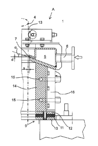
Figure 1 shows part of the arc furnace ceiling 2,
provided with an aperture 3 that constitutes the feed-
through for the vertical rod electrode 4. On top of
the edge of the aperture 3, there is arranged the
sealing device 1 shown in Figure 3, said sealing
device encasing the electrode 4. The electrode 4 is a
so-called Soderberg electrode, containing so-called
Soderberg electrode paste inside a cylindrical steel
casing 8. In another embodiment, the electrode can be
CA 02725464 2010-11-17
WO 2009/147302 PCT/F12009/050480
8
a graphite electrode. The diameter of the ,electrode 4
can be of the order 500 - 1200 mm. The sealing device
1 prevents the leakage of gases from inside the
furnace through the aperture 3 to the atmosphere, and
on the other hand, it also prevents air leakages into
the furnace.
From Figures 2 and 3 it is apparent in more detail
that the sealing device 1 includes a gas distribution
chamber 5 provided with an inlet channel 6, through
which air or nitrogen is fed in the gas distribution
chamber 5. From the gas distribution chamber 5, gas is
discharged through the slit nozzle 7 encasing the
electrode towards the electrode 4 in a direction which
is, with respect to the horizontal plane, at an angle
u that is inclined slightly upwards, and with respect
to the furnace interior directed outwardly, in order
to form an annular gas sealing around the electrode by
means of the created stagnation pressure. Gas is
advantageously discharged from the slit nozzle 7 at an
angle a, which is inclined about 15 - 25 upwards
with respect to the horizontal plane. Now the sealing
gas is exhausted mainly outwardly, and it does not
flow into the furnace.
The distance s of the slit nozzle 7 from the live
outer surface of the electrode 4 is about 10 - 40 mm.
The slit height d of the slit nozzle is about 5 mm.
The gas outlet flow rate from the slit nozzle 7 is at
least about 10 m/s. The gas pressure in the gas
distribution chamber 5 is about 3 - 4 kPa, which can
be achieved by a regular blower. It is not' necessary
to use pressurized air here. Said measures are given
by way of example in a given embodiment. The measures
may vary according to the embodiment in question.
CA 02725464 2010-11-17
WO 2009/147302 PCT/F12009/050480
9
From Figures 2 and 4 it is apparent that the sealing
device 1 is set to rest only by gravity (the weight of
the sealing device is typically for example 500 - 1000
kg, depending on the embodiment in question) on top of
the electrically insulating slide bearing 9. The slide
bearing 9 allows a horizontal sliding of the sealing
device 1, as the electrode moves in the sideways
direction. Lowest underneath is a first base ring
flange 10, which is made of steel and arranged on top
of the edge of the aperture 3. A second base ring
flange 11 made of electrically insulating material is
placed on top of the first base ring flange. A third
base ring flange 12, which is made of steel, is placed
on top of the insulating second base ring flange 11.
The sealing device 1 is placed on the third base ring
flange 12. The lower surface of the metal frame 16 of
the sealing device 1 is horizontal and machined.
Likewise, the upper surface of the third base plate
ring 12 is horizontal and machined, and thus the
sealing device 1 is free to slide thereupon
horizontally, so that the sealing device is adapted to
the lateral movement of the electrode.
From Figure 3 it can be seen that the sealing device 1
is modular and compiled of four identical segments 17,
which are detachably interconnected in order to form a
circular structure encasing the electrode 4. Figure 4
displays one such segment 17. Each segment 17 has its
own metal frame 16, in which there is integrated a gas
distribution chamber 5, which is not in flowing
communication with the gas distribution chambers 5 of
other segments, and an own inlet channel 6, through
which gas is fed into the chamber 5. The slit nozzle 7
extends along the whole 90 degrees of the arch of the
segment 17.
CA 02725464 2010-11-17
WO 2009/147302 PCT/F12009/050480
From Figures 2 - 5 it is seen that the sealing device
1 includes a number of centering rollers 13, in this
example eight rollers, which are arranged in circular
fashion on top of the gas distribution chamber 5 in
5 order to be supported against the outer surface of the
electrode 4. The centering rollers 13 maintain the
distance s between the slit nozzle 7 and the outer
surface of the electrode 4 essentially constant, but
owing to the elastic support of the rollers 13 (see
10 Figure 5), a limited movement is allowed for the
electrode 4. As the electrode 4 moves laterally, the
centering rollers 4 first yield elastically to a
certain extent. If the lateral movement of the
electrode 4 further continues, the whole sealing
device 1 begins to slide on the slide bearing 9. This
prevents the electrode 4 from being damaged.
In Figure 2 it is further seen that in the sealing
device 1 there can be a cooling element 14 made of
copper, which is attached to the metal frame 16 of the
sealing device 1 underneath the gas distribution
chamber 5. A duct 15 can be arranged inside the
cooling element 4 for the cooling water circulation.
As an alternative, the cooling element 14 can be
replaced by refractory lining, which is attached to
the metal frame 16 underneath the gas distribution
chamber 5.
The invention is not restricted to the above described
embodiments only, but many modifications are possible
within the scope of the inventive idea defined in the
appended claims.