Note : Les descriptions sont présentées dans la langue officielle dans laquelle elles ont été soumises.
CA 02727976 2010-12-14
TITLE: SELF POWER-ACQUIRING QUICK-RESPONSIVE CONTROLLABLE
REACTOR
FIELD OF THE INVENTION
This invention relates to a controllable reactor, in particular, it is the
self power-acquiring
quick-responsive controllable reactor through net-side winding to achieve
reactance and
capacity control.
BACKGROUND OF THE INVENTION
In current power grid, when the system breaks down (e.g. single phase-to-
ground fault), it is
required for the controllable reactor functioning on the power grid to quickly
increase the
capacity to its nominal capacity and control the response speed within 100ms
with capacity
not exceeding the nominal capacity of the controllable reactor so as to meet
the requirement
of inhibiting overvoltage and secondary arc current. However, current
technology fails to
satisfy such requirement (i.e. quick-response). At present, there are three
ways for DC
excitation system to obtain power: 1. external power source; 2. compensation
winding; and 3.
control-winding. If the controllable reactor does not have a reliable external
power source, it
is necessary to obtain power from itself The disadvantage for self-feeding
controllable reactor
to obtain power through control-winding is that it will generate a large
amount of harmonic
wave, along with decline of the primary voltage of the rectifier unit with the
increase of
saturation level of the reactor, while by using compensation winding it can
successfully
control the amount of the harmonic wave, but it also has the problem with
decline of the
primary voltage.
SUMMARY OF THE INVENTION
This invention provides a self power-acquiring quick-responsive controllable
reactor by
arming at solving the technical problem of overcoming the weakness of low
response speed
and power obtaining method of control winding.
In order to realize the aim of the invention, the technology adopted in this
invention is as
follows:
A coil in a main body portion of the self power-acquiring quick-responsive
controllable
reactor contains a net-side winding, a control winding, and further contains a
tertiary winding,
the tertiary winding, the control winding and the net-side winding are set in
turn on a
magnetic conductive core column of the main body portion from inside to
outside. Wherein
the net-side winding has power-acquiring taps; a quick switch is in parallel
connected with the
I
CA 02727976 2010-12-14
tertiary winding, which is controlled by the command transmitted by a control
unit in the
controllable reactor.
The power-acquiring taps of the net-side winding are connected with the
primary coil of the
rectiformer in a rectifying-filtering unit of the controllable reactor. The
output terminal of the
rectifying-filtering unit connects with the control winding. The magnetic
conductive core
column have the following structures selected from the group consisting of
single-phase
two-limb, single-phase and single synthetic limb, single-phase and three
synthetic limbs,
two-limb three-phases, or three-phase six-limb.
The invention has the following benefits and advantages:
1. Flexible control with quick responsive time. Controllable reactor having an
additional
tertiary winding is controlled through a quick switch and a control unit in
the case of short
circuit so as to meet the requirements of the quick response (response time:
within IOOms).
2. Excellent power obtaining effect. Controllable reactor set a net-side
winding to obtain the
excitation power itself for the DC excitation system including rectifying-
filtering unit and the
control winding when external power source is unusable; adjust reactance
(smooth adjustment
of capacity from 1-100%) by adjusting the DC excitation current. It can not
only smoothly
adjust the reactive power to achieve flexible current transmission but also
inhibit power
frequency/overvoltage and decrease line losses to greatly enhance the
stability and security of
the system.
3. Wide range of applications. This invention, applied to power system from
110kv (or above)
to UHV, is an important reactive power compensatory device.
BRIEF DESCRIPTION OF THE DRAWINGS
Figure 1 is the structure principle drawing of the invention;
Figure 2 is the schematic circuit diagram of one sample;
Figure 3 is schematic of the iron core and coil in the main body portion;
Figure 4 is electrical schematic drawing of the rectifying-filtering unit.
DESCRIPTION OF THE PREFERRED EMBODIMENT
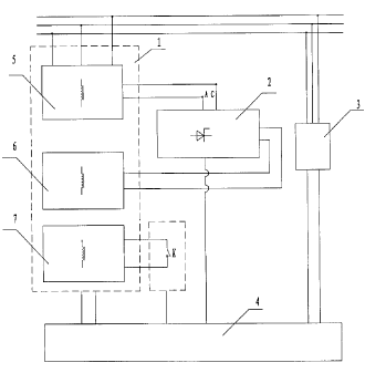
For details see the Figure 1. The main body portion I of the self power-
acquiring
quick-responsive controllable reactor is immersed inside oil tank. The coil of
the main body
portion I contains the net-side winding 5 and the control winding 6 as well as
further
including the tertiary winding 7, the tertiary winding 7, the control winding
6 and the net-side
2
CA 02727976 2010-12-14
winding 5 are set in turn on the magnetic conductive core column of the main
body portion I
from inside to outside. The tertiary winding 7 is connected with the control
unit and the
detecting unit in the controllable reactor by the quick switch K. The net-side
winding 5 has
power-acquiring taps, the rectifying-filtering unit 2 of the controllable
reactor connects to the
power-acquiring taps of the net-side winding 5, and the output terminal of the
rectifying-filtering unit 2 is connect to the control winding 6. In another
example, without the
rectifying-filtering unit 2, the control winding 6 is connected with the net-
side winding 5
through the power-acquiring taps directly.
For details see Figure 2 and Figure 3, in one example of the invention, the
magnetic
conductive core column immersed inside the oil tank is of the structure having
the
single-phase double-limb core, that is to say, the first limb and the second
limb form the left
and right magnetic yokes, and the top and bottom magnetic yokes of the
magnetic circuit.
Wherein, the tertiary winding 7, the control winding 6, and the net-side
winding 5 are set in
turn on the magnetic conductive core column from inside to outside to form the
main body
portion 1 of the controllable reactor. The primary coil of the net-side
winding 5 connects with
the transmission line and the power-acquiring taps of the net-side winding 5
connect to the
control winding 6 through the rectifying-filtering unit 2. The tertiary
winding 7 connects with
the quick switch K. The control unit 4 connects with the controllable silicon
in the
rectifying-filtering unit 2, the quick switch K, the output terminal of the
detecting unit 3, and
the terminal box connected with various sensor signals of the main body
portion 1. The
detecting unit 3 comprising of the voltage sensor, current sensor, temperature
sensor,
light/heavy gas sensor, pressure sensor, and the terminal box for leading out
the sensor signals;
the input terminal of the detecting unit 3 is also connected with the
transmission line.
For details see figure 2, the reactor of the invention is a three-phase
reactor comprising of three
single-phase reactors as example . The net-side winding 5 of each phase
comprising of coil H12
and coil H13 which are connected in parallel. The control winding 6 of each
phase comprising
of coil K14 and coil K15. Separate coils of three-phase with the same name are
connected from
end to end to form a series branch, and two series branches connect again in
parallel. The
parallel ends called "a" and "b" are connected with each output terminal of
the
rectifying-filtering unit 2. One end of the coil H12 and H13 of the net-side
winding 5 after
connection in star is connected with the three phase transmission line, and
the other end of the
coil H12 and H13 connects with a small reactor whose other end connects to the
ground. The
small neutral reactor is mainly used in the power transmission system to
inhibit over-voltage
in the case of failure and secondary arc current in short circuit. The system
does not need to
be equipped with such small reactor, when a magnetically controlled reactor is
used on the
bus line. The power-acquiring tap of the net-side winding 5 is connected with
the
rectifying-filtering unit 2, the controllable silicon group of the rectifying-
filtering unit 2
connect with the control unit 4. The detecting unit 3 used to examine the
power parameters
are connected with the transmission line and its output end with power
parameters connects
with the control unit 4, which is connected with the output terminals of the
three single-phase
reactors' second-signal terminal box. Wherein the said second-signal includes
current signal,
temperature signal, light/heavy gas signal, and pressure relief valve
protection signal, of
3
CA 02727976 2010-12-14
which output signals are connected with the input terminal of the terminal
box. The iron core
of each reactor in the example uses single-phase two-limb /return yokes core.
Figure 3 shows
how the iron core and the coil are connected. The surface of the iron core
column is covered
in turn with coils D16, K14, and H12 from inside to outside on each magnetic
conductive core
column (i.e. the first column) and the other magnetic conductive core column
(i.e. the second
column) is covered in turn with coils D17, K15, and H13 from inside to
outside. The net-side
winding and the control winding can be connected in series or in parallel, and
the single phase
module of the tertiary winding is in series.
The primary coil in rectiformer of the rectifying-filtering unit 2 is
connected with the
power-acquiring taps of the net-side winding. The primary coil of the
rectiformer and
power-acquiring taps connect with a wave filter in parallel and the secondary
coil of the
rectifornier connects with the controllable silicon group. The rectiformer and
the controllable
silicon group achieve the rectification; the wave filter including a capacitor
and a inductance,
the filtered wave is achieved by the capacitor and the inductance, connects
with the primary
coil of the rectiformer in parallel. The wave filter can be one of third-
harmonic filter,
5th-harmonic filter, and high harmonic filter, or the combination thereof.
The detecting unit 3 is used to detect the voltage, current, reactive power,
and active power of
the power grid.
The control unit 4 comprising of a data collection cabinet, local work
station, protection
control cabinet, operation cabinet and transient fault recorder cabinet which
is used to control
the thyristor's trigger angle of the rectifying-filtering unit 2 through the
parameter changing of
the power grid and the signals (e.g. voltage/current/temperature signals)
collected from the
main body portion I to alter the DC current of the control winding 6. That is
to say that
providing the alternating current power obtained by the power-acquiring taps
of the net-side
winding to the rectifying-filtering unit 2. The rectify ing-f i ltering unit 2
will adjust the AC
current to DC current, the control unit 4 will automatically control the
thyristor's trigger angle
(0 - 180 ) of the rectifying-filtering unit 2 according to the changing of the
voltage, the
reactive and active power detected by the detecting unit 3 to change the value
of the DC
current, that is, by changing the DC excitation current of the control winding
6 of the reactor's
iron core, to control the saturation level and to change the magnetic
conductivity of the iron
core. In other words, it is to change the reactance value and capacity of the
reactor.
When the system is in faulty state, the tertiary winding 7 will control the
quick switch K to
close rapidly, thus achieve short-circuit of the tertiary winding and
meanwhile shut down the
DC excitation system (including the rectifying-filtering unit 2, the control
winding 6). The
tertiary winding 7 instead of the control winding 6 will operates but under
normal working
conditions, the control winding 6 will be in work normally. The quick switch K
meets the
requirements of quick response under the controllable reactor in fault
(response time within
50ms)
When the controllable reactor is in normal working conditions (i.e. stable
adjustment process),
4
CA 02727976 2010-12-14
the quick switch K is in the on position, the tertiary winding 7 is not
working while the DC
excitation system will do. When the detecting unit 3 detects the fault
detection existed in the
power system, immediately the control unit 4 will send instructions to enable
the quick switch
K to close to make the tertiary winding 7 short circuit. In this condition,
there will be short
circuit impedance between the net-side winding 5 and the tertiary winding 7,
which makes the
controllable reactor reach to a certain inductance value. When the detecting
unit 3 detects the
failure signal (e.g. single-phase earth fault, three-phase voltage or current
imbalance), the DC
excitation system will quit immediately, which means that the control unit
send control
signals to quickly shut down the thyristor's trigger angle to make the
thyristor in
non-conducting state. At that time, the DC excitation current is zero and the
control-winding is
not work.
The quick switch can be high voltage sulphur hexafluoride circuit-breaker with
model
LW24-40.5 to meet requirements of quick response under the controllable
reactor in fault,
response time is within 50ms.
20
5