Note : Les descriptions sont présentées dans la langue officielle dans laquelle elles ont été soumises.
CA 02744382 2011-06-22
1
GOLF SHOES
BACKGROUND OF THE INVENTION
1. Field of the Invention
The present invention relates to golf shoes, especially to a pair of golf
shoes that support the center gravity of players shifted during the swing
and keep the players' bodies stable. Thus both power and accuracy of the
strike are maintained. Therefore, the player can have a good swing.
1.0
2. Description of Related Art
Refer to Fig. 7, Fig. 8 and Fig. 9, schematic drawings showing the
assembly between golf spikes and shoe soles of golf shoes available now
are revealed. A receptacle 8 is connected with a shoe sole 7 and a
threaded round hole 81 is set on the receptacle 8. The threaded round hole
81 is corresponding to and threaded with a round threaded rod 91
arranged above golf spikes 9. However, after being worn for a period of
time, the golf spikes 9 available now is easy to slip off. This causes
inconvenience in use.
For right-handed players, the body weight is distributed evenly on
both soles of the feet in the beginning of the swing. While taking a back
swing, the body weight moves at the direction a club moves so that the
CA 02744382 2011-06-22
2
center of gravity gradually moves onto the right side of the soles of the
feet. When the club is swung up to reach the top point, the center of
gravity is stacked over the right side of the soles of the feet completely.
While taking a downswing, the player turns the upper body in opposite
direction, and the body gravity is gradually shifted to the left side of the
soles of the feet. After finishing the swing, the weight is evenly
distributed on both soles of the feet again. On the other hand, for
left-handed players, the center of gravity is shifted to the right side of the
soles of the feet.
During the swing, the player is easy to lose balance. Especially when
the back swing starts, the center of gravity is totally shifted to one side of
the soles of the feet. Thus that side of the sole of the foot is pressed by
the
body weight and is projecting from the limited area supported by the shoe
sole. Thus the grip force at that side of the sole of the foot is
significantly
reduced. This leads to instability of the lower limbs of the player and the
body position is moved. Thus the shot losses power and the accuracy of
the downswing is affected. Therefore, it's difficult for the player to hit the
ball and reach the optimal position.
SUMMARY OF THE INVENTION
Therefore it is a primary object of the present invention to provide
CA 02744382 2011-06-22
3
golf shoes that support golf players whose center of gravity changes
throughout golf swings so as to help them maintain balance. Thus the golf
player can have a smooth and stable swing.
In order to achieve above object, golf shoes of the present invention
include auxiliary supports arranged at the positions that the player's
weight shifted to during the strike. Thus the shifted center of gravity of
the player is supported by the auxiliary supports and the lower body of
the player is stabilized throughout the lift. The center of gravity of the
body has not swayed. The force of the swing and the energy transferred to
the ball are maintained due to the firm base of the lower body. Without
common faults, the accuracy is dramatically improved. Therefore the
player can make a good shot easily and smoothly.
BRIEF DESCRIPTION OF THE DRAWINGS
The structure and the technical means adopted by the present
invention to achieve the above and other objects can be best understood
by referring to the following detailed description of the preferred
embodiments and the accompanying drawings, wherein
Fig. I is a schematic drawing showing a left sole and a right sole of golf
shoes for left-handed players .according to the present invention;
Fig. 2 is a cross sectional view of the left sole and the right sole of golf
CA 02744382 2011-06-22
4
shoes for left-handed players according to the present invention;
Fig. 3 is a schematic drawing showing a left sole and a right sole of golf
shoes for right-handed players according to the present invention;
Fig. 4 is a cross sectional view of the left sole and the right sole of golf
shoes for right-handed players according to the present invention;
Fig. 5 is an explosive view of golf shoe spikes and a receptacle of an
embodiment according to the present invention;
Fig. 6 is a cross sectional of an assembly having golf shoe spikes and a =
receptacle of an embodiment according to the present invention;
Fig. 8 is an explosive view of golf shoe spikes and a receptacle of golf
shoes available now;
Fig. 9 is a cross sectional of an assembly having golf shoe spikes and a
receptacle of golf shoes available now.
DETAILED DESCRIPTION OF THE PREFERRED EMBODIMENT
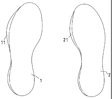
As shown in Fig. I, golf shoes of the present invention are designed
according to the movement of player's body weight while making a
CA 02744382 2011-06-22
Refer to Fig. 1 and Fig. 2, golf shoes for left-handed players are
revealed. An auxiliary support 11 extends out of an edge on the left side
of a left shoe sole 1 of golf shoes and an edge on the left side of a right
shoe sole 2 of golf shoes is also arranged with an auxiliary support 21.
5
Refer to Fig. 3 and Fig. 4, as to golf shoes for right-handed players,
an auxiliary support 31 extends from an edge on the right side of a right
shoe sole 3 of golf shoes while an auxiliary support 41 extends from an
edge on the right side of a left shoe sole 4.
Back to Fig. 1 and Fig. 2, when a left-handed player takes a swing
with golf shows of the present invention, his shifts the body weight from
both feet at start-up to the lift side of each sole of the feet along with the
twist of the body to the left. The center of gravity of the body moves to
the left side of the soles of the feet totally when the swing reaches the top.
Now by means of the auxiliary support 11 on the left side of the left shoe
sole 1 and the auxiliary support 21 on the left side of the right shoe sole 2
of the golf shoes, the center of gravity shifted to the left side of the soles
of the feet gets good support in the strike. Thus the center of gravity of
the body is maintained steadily. The left-handed player keeps good
balance and takes a downswing to strike the ball.
CA 02744382 2011-06-22
6
On the other hand, refer to Fig. 3 and Fig. 4, for right-handed players,
they wear golf shoes having the auxiliary support 31 extending on the
right side of the right shoe sole 3 and the auxiliary support 41 on the right
side of the left shoe sole 4. Thus for the right-handed players, the body
weight is gradually shifted to the right side of the soles of the feet. As
shown in Fig. 3, by means of the auxiliary support 31 on the right side of
the right shoe sole 3 and the auxiliary support 41 on the right side of the
left shoe sole 4 of the golf shoes, the gravity of the right-handed player
shifted to the right side of the body gets support, the lower limbs of the
player are more stable and the position of the player is not moved during
the swing. Moreover, during the following rotation process in the
downswing, the soles of the feet of the player step on the shoe soles
stably without resistance, the swing is completely smoothly, and the ball
is struck well.
Furthermore, in order to improve the stability during the swing
process, refer to Fig. 5 and Fig. 6, the length D of projections on one side
of golf shoe spikes 5 is larger than the length d of projection on the other
side of the golf shoe spikes 5. Thereby while assembling golf shoes for
left-handed players, one side of the golf shoe spikes 5 having projections
with larger length D is set near the left side of the left shoe sole 1 while
the other side of the golf shoe spikes 5 having projections with shorter
length d is set around the right side. The golf shoe spikes 5 are assembled
CA 02744382 2011-06-22
7
on the right shoe sole 2 in the similar way. Thus while the left-handed
player making a swing and the body weight shifting to the left side, the
projections with larger length D on one side of the golf shoe spikes 5 are
pushed into the ground. This helps the golf player grip the ground firmly
__ and keeps the lower body (the foundation) steady so as to make a good
swing.
On the other hand, for right-handed players, one side of the golf shoe
spikes 5 having projections with larger length D is set near the right side
__ of the right shoe sole 3 while the other side of the golf shoe spikes 5
having projections with shorter length d is set near the left side. The golf
shoe spikes 5 are assembled on the left shoe sole 4 in the similar way.
Thereby while taking a swing, the gravity of the right-handed player is
shifted to the right side and the projections with larger length D on one
__ side of the golf shoe spikes 5 are placed into the ground so as to make the
player grip the ground more tightly by the golf shoes.
Refer to Fig. 5 and Fig. 6, in order to prevent the golf shoe spikes 5
from rotating and loosening due to torque in the swing or walking, a
__ receptacle 6 connected to the shoe soles of the golf shoes includes a
polygonal socket 61 and a threaded hole 62 arranged at the center of the
socket 61. One end of the golf shoe spikes 5 facing the socket 61 is
disposed with a polygonal assembly block 51 so as to connect and
CA 02744382 2011-06-22
_
8
assemble with the socket 61 of the receptacle 6. A through hole 52
corresponding to the threaded hole 62 of the receptacle 6 is set on the
center of the golf shoe spikes 5. A common screw 53 passes through the
through hole 52 of the golf shoe spikes 5 to be threaded and fastened with
the threaded hole 62 of the receptacle 6. Thus the assembly block 51 of
the golf shoe spikes 5 and the socket 61 of the receptacle 6 against each
other keep the golf shoe spikes 5 from rotating and loosening in the swing
or during the walking. Moreover, the screw 53 is a screw with general
specification and is available on the market now. Thus while removing
the golf shoe spikes 5, users only need a common screw driver for
loosening and tightening the screw 53. This enhances the convenience in
use.
In accordance with the structure and the embodiments mentioned
above, the present invention has following advantages:
1. According to the shift of the body gravity of golf players, each shoe
sole of the golf shoes is arranged with an auxiliary support extending out
of an edge of the position that the body gravity shifts to during the swing.
Thereby the shifted body gravity of the player is supported by the
auxiliary support and the foundation of the player is steady. Thus the
player can keep balance and the body positioned is not moved. Moreover,
both the striking force accumulated during the back swing process and
CA 02744382 2013-09-10
9
the accuracy of downswing are maintained. Therefore, the player can make a
perfect
swing with increasing strength and accuracy.
2. The receptacle on the shoe sole of the golf shoes includes the polygonal
socket while
the polygonal assembly block corresponding to the socket of the receptacle is
disposed on
one end of the golf shoe spikes facing the socket. Thus the rotating and
loosening of the
golf shoe spikes caused by the torque during the swing or walking can be
avoided by the
assembly block of the golf shoe spikes and the socket of the receptacle
connected and
against each other.
While the above description provides specific examples of embodiments, it will
be appreciated that additional advantages and modifications will readily occur
to those
skilled in the art. Accordingly, what has been described above has been
intended to be
illustrative of the invention and non-limiting. The scope of the claims should
not be
limited by the specific embodiments set forth in the examples but should
instead be given
the broadest interpretation consistent with the description as a whole.