Note : Les descriptions sont présentées dans la langue officielle dans laquelle elles ont été soumises.
CA 02760421 2011-09-26
1
WO 2010/111997
Applicator device for cosmetic and/or medical use
The present invention relates to an applicator device for cosmetic and/or
medical use.
It is known to cool a person's skin for medical and/or cosmetic reasons. US
2006/0067962
Al discloses a skin-cooling means which comprises components which make it
possible
both to cool the skin rapidly and to cool the skin over a relatively long
period. For cooling the
skin, this known means basically comprises water, alcohol, a surfactant and
water-soluble
silicone. US 2006/0067962 Al discloses an applicator in which the skin-cooling
means is
arranged on a substrate. In this case, the substrate is attached in the form
of a plaster to a
corresponding portion of skin.
WO 03/000089 A2 describes a disposable applicator device with which in
particular cosmetic
liquids or creams can be applied to a skin surface to be treated of a human
body. In this
case, the liquid is stored in a storage layer and dispensed onto an applicator
surface via a
liquid-controlling control layer. An impermeable layer is also provided which
prevents the
liquid from flowing off the applicator surface.
DE 199 42 566 Al describes a cooling pad for use in cooling processes, which
cooling pad
contains a salt mixture mixed with a gelling agent and keeps this mixture
separated from an
activator inside the cooling pad until they are brought together. When the
activator, which
may be water, is added to the salt mixture mixed with the gelling agent, this
results in a
cooling reaction in which the temperature of the cooling pad falls to
approximately 0 C.
WO 2004/043534 Al discloses an applicator device comprising an applicator
element for
applying a substance contained in a substance chamber to a portion of skin. In
this case, the
applicator part can contain a vibrator and a means with which the skin can be
cooled or
heated.
The object of the present invention is to configure an applicator device in
such a way that a
cosmetic and/or medical substance which is dispensed onto a part of a person's
skin or body
requiring care or treatment is applied in the form of a cooling or heating
substance, a gentle
vibration massage occurring simultaneously to stimulate lymphatic activity.
CA 02760421 2011-09-26
2
This object is achieved by an applicator device having the features of claim
1.
The main advantage of the present invention is that portions of a person's
skin requiring care
or treatment, in particular the eye region or for example a part of the body
affected by
cellulite or pain or tension, are made to vibrate by a gentle vibration
massage to stimulate
lymphatic activity and/or blood flow, any possible swelling of said skin
portions decreasing.
At the same time a substance which has a nurturing and/or medicinal effect
(for example
which reduces swelling, promotes blood flow or has a draining or dehydrating
effect) is
advantageously applied to the skin portions in question via the applicator
device according to
the invention. Because said substance is applied to a skin portion with a
simultaneous
vibration effect, particularly effective and fast-acting skin care is
possible. It is particularly
advantageous that the medicinal and/or cosmetic substance can be applied in a
cooled or
heated form. As a result, the effect of the substance and thus also the
physiological skin and
body reactions can be improved and accelerated. It is also conceivable to use
the applicator
device 1 according to the invention for treating orthopaedic conditions or for
preferably post-
operative treatment of scars and tissue and in connection with other
indicators, for example
palliatively for pain relief or in the case of inflammatory diseases.
A further basic advantage of the present invention is that the applicator
device is configured
in such a way that the applicator part containing the substance to be applied
is formed as a
disposable part, in such a way that the vibration part of the applicator
device according to the
invention can be used selectively for different substances. In this case, the
disposable part
can simultaneously also comprise the means causing cooling or heating. For
example, these
means may be reactants which are known per se.
In an advantageous configuration of the present invention there is also the
possibility of light
therapy. Within the context of a NASA research programme, it has been proved
in particular
that light therapy, in which light is preferably produced using light emitting
diodes (LEDs),
can accelerate the healing process of wounds and the growth of human tissue
(cell
generation). In addition, it has been found that the light energy emitted by
the LEDs
improves the metabolism of the cells and accelerates cell regeneration. Light
therapy - not
least owing to its uplifting effect - is thus an effective method for the
treatment and
prophylaxis of many illnesses.
CA 02760421 2011-09-26
3
Advantageous configurations of the invention emerge from the dependent claims.
The invention and its configurations are described in detail below in
conjunction with the
figures, in which:
Fig. 1 schematically shows a side view of the applicator device according to
the invention;
Fig. 2 schematically shows a longitudinal section through the applicator
device according to
the invention of Fig. 1;
Fig. 3 and 4 are schematic drawings illustrating the principle of an activator
device and
Fig. 5 shows a development of the invention.
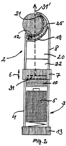
In the manner which can be seen in particular in Fig. 1 and 2, the present
applicator device 1
basically consists of an applicator part 2, which comprises a substance 27 to
be applied and
the means causing the cooling or heating of this substance 27, and a vibration
part 3.
According to Fig. 2, the vibration part 3 basically comprises, in a lower
housing part 4, an
energy source 5, preferably in the form of a battery, a control part 13 which
is preferably
arranged at the lower end of the housing part 4 and comprises at least an
on/off switch, a
vibration element 10 which produces oscillations in the longitudinal direction
of the vibration
part 3 (see arrow 6) and which is supplied with current by the energy source
5, and a
connecting part 7, preferably arranged on the upper side of the housing part
4, for
connecting the upper housing part 8 to the lower housing part 4. The
oscillation amplitude of
the vibrations of the vibration element 10 can preferably also be adjusted on
the control part
13. The vibration element 10 can for example be a piezo component. It should
be noted that
the energy source 5 can also be formed via the possibility of a connection to
an alternating
or direct voltage network.
The applicator part 2 which can be attached to the vibration part 3 using the
connecting part
7 basically comprises, in the upper housing part 8, an applicator element 9
via which a
medicinal and/or cosmetic substance to be applied to a portion of skin can be
applied to said
portion of skin. For example, the applicator element 9 is a "roll-on" element
in the form of a
spherical part 11 which dispenses the substance via its surface and is known
from the
conventional "deo-rollers". The spherical part 11 is contained in a
corresponding,
CA 02760421 2011-09-26
4
approximately hemispherical trough 12 of the upper housing part 8. Inside the
upper housing
part 8 there is a substance chamber 25 containing the substance 27 to be
applied, from
which substance chamber the substance is transferred to the surface of the
spherical part 11
during use of the applicator device 1. The spherical part 11 is set in
rotation via sliding
movements on the skin and dispenses the substance 27 transferred from the
substance
chamber 25 onto the portion of skin. A roller-shaped part forming the
applicator element 9
can also be provided instead of the spherical part 11.
With reference to Fig. 3, the substance chamber 25 is separated by means of a
wall part 19
from a reaction chamber 20 in which cooling energy for cooling the substance
27 or heat for
heating the substance 27 is produced during use of the applicator device 1, as
described in
detail below. The substance 27 is dispensed to the spherical part 11 in a
manner known per
se via the trough wall 21 limiting the trough 12. In order to prevent the
substance 27 from
drying out in the region of the applicator element 9, allow re-use and ensure
the required
hygiene and protection of the activator 22, the entire applicator part 2,
preferably configured
as a disposable part, is preferably contained for distribution in a cover 28
which is
impermeable to moisture, is only opened during use of the applicator part 2
and is distanced
therefrom (see Fig. 4). The cover 28 can also be used for advertising and
decorative
purposes.
The means required for producing cooling energy or heat are located in the
reaction
chamber 20 adjacent to the wall part 19 on the side remote from the substance
chamber 25.
In very general terms, this means is a schematically shown activator 18 which
is able to
produce cooling energy for cooling the substance 27 or heat for heating it.
For example, in the manner known from DE 199 42 566 Al, a salt mixture 15,
which is
mixed with a gelling agent and is separated by a dividing wall 17 from a
chamber 28
containing an activator 18 in the manner shown in Fig. 4, is located in the
reaction chamber
20 as a first means for producing cooling energy. The activator 18 forms a
second means.
For example, the activator 18 consists of water. The gelling agent can consist
of methyl
cellulose sodium. When the two means 15 and 18 separated from one another by
the
dividing wall 17 are brought together, the cooling energy required to cool the
substance 27
immediately at the wall part 19 is produced.
CA 02760421 2011-09-26
In order to bring the two means 15 and 18 together, the dividing wall 17 is
preferably
severed automatically when the two housing parts 4 and 8 are connected using
the
connecting part 7. For this purpose, a pin part 16 is arranged on the
connecting part 7 or on
the lower housing part 4, which pin part is expediently arranged centrally on
the connecting
part 7 and projects beyond the connecting part 7 towards the dividing wall 17.
When the
lower housing part 4 is connected to the upper housing part 8, the pin part 16
enters, in the
manner shown in Fig. 4, a recess 29 in a base 26 limiting the upper housing
part 8 and the
chamber 30 from the lower housing part 4. The base 26 and the recess 29 are
configured to
be so flexible that when the housing parts 4 and 8 are connected a pressure
applied by the
pin part 16 acts on the dividing wall 26 and causes the dividing wall 17 to
break in such a
way that the two means 15 and 18 come into contact with each other to produce
cooling
energy. This is shown in Fig. 3.
The substance 27, preferably a liquid, a cream or a gel, which is contained in
the substance
chamber 25 has a nurturing, in particular also a swelling reduction effect.
Owing to its
consistency it facilitates the sliding action of the spherical part 11 and
thus optimises for
example a gentle lymphatic drainage. In particular, the present applicator
device 1 is suitable
for highly effective care of the eye regions, which may be swollen for example
in the morning
or generally in the case of tiredness. In the case of the present applicator
device 1, the effect
of the nurturing substance 27 is increased by cooling energy or heat which is
produced and
also by the oscillations which are produced in the vibration part 3 and
transferred to the
applicator part 2. The applicator device 1 can also be used in the case of
headaches,
preferably in the region of the temples or forehead. It is also conceivable,
in the case of
colds or hay fever, to produce heat from the outside in the region of the neck
or maxillary
sinus in order to achieve a healing effect, in particular in conjunction with
the substance 27.
For oscillation transfer, the vibration element 10 is coupled to the upper
housing part 8 when
the housing parts 4 and 8 are connected. As is known, the connecting part 7
preferably
comprises a plug-in, snap or screw connection.
A configuration of the invention in which the applicator part 2 is in the form
of a disposable
part is particularly advantageous. As a result, different applicator parts 2
having different
substances and also different heating or cooling means can selectively be
connected to the
same vibration part 3.
CA 02760421 2011-09-26
6
In the manner indicated in Fig. 2 by way of continuous lines, the present
applicator device 1
can comprise a light source 31, the light from which can be radiated onto the
skin or body
parts to be treated in order to produce therein the effect of promoting wound-
healing or cell
regeneration or the uplifting effect. In this case, the light source 31 is
preferably arranged in
the connecting part 7 (Fig. 2) or in the pin part 16 (Fig. 3) or in the
vibration part 3. The
applicator part 2 and the corresponding parts thereof (for example base 26,
activator 22,
dividing wall 17, reaction chamber 20, wall part 19, trough wall 21, substance
27, means 15
and 18) and the applicator element 9 are formed so as to be transparent, in
such a way that
the light ray 31' produced by the light source 31 can pass unhindered through
the applicator
part 2 and the applicator element 9 to the skin or body parts to be treated.
The light source
31 can be configured in such a way that it can selectively produce light in
different colours,
depending on the application.
In contrast to the configuration according to Fig. 2 to 4, it is also
conceivable to provide the
substance to be applied, in accordance with Fig. 5, in the applicator element
9, in other
words in the spherical part 11 or in the corresponding roller-shaped part
itself, the applicator
element 9 then having a cover consisting of a semi-permeable material. In this
way, during
use of the applicator device 1 the substance can transfer to the skin or body
parts the gentle
pressure exerted on the applicator element 2. In this case, depending on the
application the
surface of said cover can be configured in an amorphous manner or with pimples
for
promoting blood flow.
CA 02760421 2011-09-26
7
List of reference numerals
I applicator device
2 applicator part
3 vibration part
4 lower housing part
energy source
6 arrow
7 connecting part
8 upper housing part
9 applicator element
vibration element
11 spherical part
12 trough
13 control part
means
16 pin part
17 dividing wall
18 means
19 wall part
reaction chamber
21 wall region
22 activator
substance chamber
26 base
27 substance
28 cover
29 recess
chamber
31 light source
31' light ray