Sélection de la langue

Search

Sommaire du brevet 2763305 

Énoncé de désistement de responsabilité concernant l'information provenant de tiers

Une partie des informations de ce site Web a été fournie par des sources externes. Le gouvernement du Canada n'assume aucune responsabilité concernant la précision, l'actualité ou la fiabilité des informations fournies par les sources externes. Les utilisateurs qui désirent employer cette information devraient consulter directement la source des informations. Le contenu fourni par les sources externes n'est pas assujetti aux exigences sur les langues officielles, la protection des renseignements personnels et l'accessibilité.

Disponibilité de l'Abrégé et des Revendications

L'apparition de différences dans le texte et l'image des Revendications et de l'Abrégé dépend du moment auquel le document est publié. Les textes des Revendications et de l'Abrégé sont affichés :

  • lorsque la demande peut être examinée par le public;
  • lorsque le brevet est émis (délivrance).
(12) Brevet: (11) CA 2763305
(54) Titre français: ENSEMBLE POULIE AMOVIBLE
(54) Titre anglais: DETACHABLE PULLEY ASSEMBLY
Statut: Octroyé
Données bibliographiques
(51) Classification internationale des brevets (CIB):
  • A63B 22/00 (2006.01)
  • A63B 21/00 (2006.01)
  • A63B 21/055 (2006.01)
  • A63B 22/04 (2006.01)
(72) Inventeurs :
  • ENDELMAN, KEN (Etats-Unis d'Amérique)
  • MASTERSON, BRIAN (Etats-Unis d'Amérique)
(73) Titulaires :
  • BALANCED BODY, INC. (Etats-Unis d'Amérique)
(71) Demandeurs :
  • BALANCED BODY, INC. (Etats-Unis d'Amérique)
(74) Agent: NEXUS LAW GROUP LLP
(74) Co-agent:
(45) Délivré: 2012-08-21
(86) Date de dépôt PCT: 2010-07-01
(87) Mise à la disponibilité du public: 2011-01-06
Requête d'examen: 2011-12-20
Licence disponible: S.O.
(25) Langue des documents déposés: Anglais

Traité de coopération en matière de brevets (PCT): Oui
(86) Numéro de la demande PCT: PCT/US2010/040745
(87) Numéro de publication internationale PCT: WO2011/002976
(85) Entrée nationale: 2011-12-20

(30) Données de priorité de la demande:
Numéro de la demande Pays / territoire Date
12/496,312 Etats-Unis d'Amérique 2009-07-01

Abrégés

Abrégé français

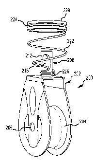
L'invention concerne un ensemble poulie permettant de fixer de manière amovible un cordon pour bras à un appareil d'exercice. L'ensemble poulie comprend un étrier comportant une partie centrale et une paire de parties branches parallèles, la partie centrale étant traversée par un trou, une roue de poulie supportée de manière rotative entre les parties branches de l'étrier sur un axe, ainsi qu'une tige allongée pourvue d'une partie arbre s'étendant axialement et faisant saillie à travers le trou. La partie arbre possède une extrémité distale à travers laquelle est formée une fente en L. La fente en L forme une extrémité en forme de crochet au niveau de la partie arbre. Un ressort hélicoïdal conique situé au-dessus de la partie arbre de la tige possède une petite extrémité et un grand diamètre autour de la partie arbre de la tige. Le ressort sollicite l'extrémité en forme de crochet pour l'écarter d'un boulon à il situé sur l'appareil d'exercice afin de maintenir l'ensemble poulie relié au boulon à il et, par conséquent, fixé à l'appareil d'exercice.


Abrégé anglais


A pulley assembly for removably fastening an arm cord to an
exer-cise apparatus is disclosed. The pulley assembly includes a yoke having a
central
portion and a pair of parallel leg portions, the central portion having a bore

therethrough, a pulley wheel rotatably supported between the yoke leg portions
by
an axle, and an elongated stem having an axially extending shaft portion
protrud-ing through the bore. The shaft portion has distal end portion having
an L shaped
slot formed therethrough. The L shaped slot forms a hook shaped end to the
shaft
portion. A tapered coil spring over the shaft portion of the stem, has a small
end
and a large diameter around the shaft portion of the stem. The spring biases
the
hooked end away from an eyebolt on the exercise apparatus to keep the pulley
as-sembly engaged with the eye bolt and hence fastened to the exercise
apparatus.


Revendications

Note : Les revendications sont présentées dans la langue officielle dans laquelle elles ont été soumises.


What is claimed is:


1. A pulley assembly for removably fastening an exercise cord to an exercise
apparatus, the pulley assembly comprising: a yoke having a central portion and
a pair
of parallel leg portions, the central portion having a bore therethrough; a
pulley wheel
rotatably supported between the yoke leg portions by an axle; an elongated
stem
having an axially extending shaft portion protruding through the bore, the
shaft portion
having a distal end portion having an L shaped slot formed therethrough
wherein the
slot has an axial portion and a radial portion, the radial portion opening
through the side
of the shaft portion, the axial portion terminating short of the end of the
shaft portion,
the slot forming a hook shaped end to the shaft portion; a tapered coil spring
over the
shaft portion of the stem having a small end and a large diameter end, wherein
the
small end is wrapped around the shaft portion of the stem; and wherein the
hook can
move within the spring to fasten the pulley to the exercise apparatus.


2. The assembly according to claim 1 further comprising an annular bushing
captured
in the large diameter end of the coil spring.


3. The assembly according to claim 1 wherein the stem further comprises a
raised
annular rib between the yoke and the slot and wherein the small end of the
spring is
wrapped around the stem between the yoke and the raised annular rib on the
stem.

4. The assembly according to claim 2 wherein the bushing has an annular
peripheral
groove receiving the large diameter end of the coil spring.


5. In a reformer exercise apparatus having a generally rectangular frame, a
pair of
parallel tracks, a carriage movably mounted on the tracks for movement toward
and
away from a foot end of the frame, and one or more elastic members biasing the

carriage toward the foot end of the frame, and a trapeze assembly fastened to
a head
end of the frame, a pulley assembly removably fastened to one of a plurality
of eyebolts
mounted to the trapeze assembly, the pulley assembly comprising: a yoke having
a
central portion and a pair of parallel leg portions, the central portion
having a bore


8


therethrough; a pulley wheel rotatably supported between the yoke leg portions
by an
axle; an elongated stem having an axially extending shaft portion protruding
through the
bore, the shaft portion having a distal end portion having an L shaped slot
formed
therethrough wherein the slot has an axial portion and a radial portion, the
radial portion
opening through the side of the shaft portion, the axial portion terminating
short of the
end of the shaft portion, the slot forming a hook shaped end to the shaft
portion; a
tapered coil spring over the shaft portion of the stem having a small end and
a large
diameter end, wherein the small end is wrapped around the shaft portion of the
stem;
and wherein the hook can move within the spring to fasten the pulley to the
exercise
apparatus.


6. The assembly according to claim 5 further comprising an annular bushing
captured
in the large diameter end of the coil spring.


7. The assembly according to claim 5 wherein the stem further comprises a
raised
annular rib between the yoke and the slot and wherein the small end of the
spring is
wrapped around the stem between the yoke and the raised annular rib on the
stem.

8. The assembly according to claim 6 wherein the bushing has an annular
peripheral
groove receiving the large diameter end of the coil spring.


9

Description

Note : Les descriptions sont présentées dans la langue officielle dans laquelle elles ont été soumises.


CA 02763305 2011-12-20
WO 2011/002976 PCT/US2010/040745

DETACHABLE PULLEY ASSEMBLY
BACKGROUND OF THE DISCLOSURE

Field of the Disclosure

[0001]The present disclosure relates to pulleys. In particular, it relates to
a pulley
assembly utilized in physical exercise apparatus.

State of the Art

[0002] Exercise machines such as reformers utilized in the performance of
physical
exercises originated by Joseph Pilates often employ pulleys through which
cords are
extended. One end of each of such a cord is typically attached to a spring
biased
carriage and the other end attached to a grip loop or handle. The pulley is in
turn
fastened to one end of the reformer or may be attached to an upright member
extending from the frame of the reformer. The pulley is typically bolted to
the upright
member or may be adjustably fastened to the upright member through a slot in
the
upright member. Such installations of pulleys are relatively permanent, as
they are
fairly difficult to remove, requiring the pulley to be unbolted from the
upright to which
it is attached. Therefore, if many alternative pulley locations are desired to
be used,
either additional pulleys must be mounted on the upright members or changing
them
requires a substantial amount of time to complete.

SUMMARY OF THE DISCLOSURE

[0003] A removable pulley assembly for use in an exercise apparatus such as a
reformer is disclosed which permits the pulley to be attached to any
appropriately
sized device such as an eyebolt or hook. The removable pulley assembly
preferably
includes a yoke having a central portion and a pair of parallel leg portions.
The
central portion has a bore therethrough, and a pulley wheel is rotatably
supported
between the yoke leg portions by an axle. An elongated stem having an axially
extending shaft portion protrudes through the bore. The shaft portion has a
distal
end portion having an L shaped slot formed therethrough. The L shaped slot
forms a
hook shaped end to the shaft portion of the stem. A tapered coil spring over
the
shaft portion of the stem has a small end wrapped onto the shaft portion and a
large
diameter around the shaft portion of the stem. The hooked end can be hooked
onto
1


CA 02763305 2011-12-20
WO 2011/002976 PCT/US2010/040745

an eyebolt. The spring biases the hooked end away from the eyebolt on the
exercise apparatus to keep the pulley assembly engaged with the eye bolt and
hence fastened to the exercise apparatus.
[0005] In a preferred embodiment, the pulley assembly is for removably
fastening
an exercise cord to an exercise apparatus. The pulley assembly comprises a
yoke
having a central portion and a pair of parallel leg portions, the central
portion having
a bore therethrough. A pulley wheel is rotatably supported between the yoke
leg
portions by an axle. An elongated stem having an axially extending shaft
portion
protrudes through the bore. The shaft portion has a distal end portion having
an L
shaped slot formed therethrough with an axial portion and a radial portion.
The
radial portion opens through the side of the shaft portion. The axial portion
terminates short of the end of the shaft portion, forming a hook shaped end to
the
shaft portion. The assembly also has a tapered coil spring over the shaft
portion of
the stem having a small end and a large diameter end, wherein the small end is
wrapped around the shaft portion of the stem.

BRIEF DESCRIPTION OF THE DRAWINGS

[0004]The disclosure will be better understood and objects, other than those
set
forth above, will become apparent when consideration is given to the following
detailed description. Such description makes reference to the accompanying
drawings wherein:

[0005] Fig. I is a perspective view of a reformer exercise apparatus
incorporating
one or more pulley assemblies in accordance with the present disclosure.

[0006] Fig. 2 is a separate perspective view of an exemplary embodiment of a
pulley
assembly in accordance with the present disclosure.

[0007] Fig. 3 is an axial cross sectional view of the pulley assembly shown in
Figure
2.

[0008] Fig. 4 is a side view of the pulley assembly shown in Fig. 2 attached
to an
eyebolt secured to an upright frame member of the reformer exercise apparatus
shown in Figure 1.

2


CA 02763305 2011-12-20
WO 2011/002976 PCT/US2010/040745
DETAILED DESCRIPTION

[0009] In the following description, numerous specific details are set forth
in order to
provide a more thorough disclosure. It will be apparent, however, to one
skilled in
the art, that the art disclosed may be practiced without these specific
details. In
some instances, well-known features may have not been described in detail so
as
not to obscure the art disclosed.

[0010]A perspective view of a reformer apparatus 100 is shown in Fig. 1. This
particular reformer 100 has a trapeze assembly 130 installed at its head end.
The
exercise apparatus 100 comprises a generally rectangular frame 102 having a
head
end 104 and a foot end 106 and a pair of parallel track or rail members 108
separating the head end 104 from the foot end 106. Each of the rail members
108
has an outwardly open T shaped slot 110 running the length of each of the rail
members 108. A movable carriage 111 rides on four roller/guide wheel
assemblies
112, one of which can barely be seen in FIG. 1, fastened to the underside of
the
carriage 111. These wheel assemblies 112 roll on the track members 108 to
support
and guide movement of the carriage Ill back and forth along the track members
108 of the frame 102. A plurality of elastic members, e.g., springs 114 are
selectively
connected between the carriage 111 and the foot end 106 to bias the carriage
111
toward the foot end 106.

[0011]A foot bar assembly 116 is removably fastened to the frame 102 near the
foot
end 106 so as to provide a stationary support for a user of the apparatus 100
to push
against while reclining or sifting on the carriage 111 in order to move the
carriage
111 back and forth along the track members 108. The foot end 106 also includes
a
flat foot topped foot platform 118 for a user to place one foot on while the
other foot
is placed on the carriage 111 for standing exercises on the apparatus 100.

[0012]The head end 104 is designed to space the rail members 108 rigidly
apart.
The head end 104 is preferably a rectangular box tubular extrusion member made
preferably of aluminum fastened to the head ends of the rail members 108.

[0013]The carriage 111 comprises a flat support platform 120 which has a
generally
rectangular shape. A cushion pad 122 is secured to an upper surface of the
platform
120. A pair of shoulder stops 124 are spaced apart near one end of and
fastened to
the rectangular platform 120. These shoulder stops 124 engage with a user's
3


CA 02763305 2011-12-20
WO 2011/002976 PCT/US2010/040745
shoulders when the user lies on his or her back on the carriage 111 while
exercising
on the apparatus 100. A padded headrest 126 is fastened via a hinge at a base
end
to the platform 120 between the shoulder stops 124.

[0014]A trapeze assembly 130 is slidably installed in the T shaped slots 110
in the
rails 108. The trapeze assembly 130 includes an upside down U shaped or arched
frame 132 that has two parallel legs 134 joined by a U shaped upper section
136,
typically has a trapeze bar 138 suspended from the legs 134, and has a pair of
support bracket assemblies 140 that slide into the T shaped slots 110 in the
rails
108. These support bracket assemblies 140 permit the trapeze frame 132 to be
rigidly positioned in an upright operating position at the head end 104 of the
frame
102 as shown in FIG. 1.

[0015]The trapeze frame 132 has adjustable exercise cord pulleys 144
adjustably
attached to the vertical frame legs 134 of the trapeze frame 132. These permit
a
user to attach one end of an exercise cord (not shown) to the reformer
carriage 111
and pass the other end through the pulley 144 to a hand grip to then perform
resistance based exercises via the user's arms or legs, while standing,
sitting or
reclining on the carriage 111.

[0016]There are also a number of eyebolts 142 fastened at various heights on
the
trapeze frame members 134 from the reformer head end 104. A spring (not shown)
may be attached to one or more of these eyebolts to facilitate various
additional
exercise regimens. Alternatively springs may be attached to the trapeze bar
138 and
thence to one of the eyebolts 142 to provide a resilient bias to the trapeze
bar for
other exercise purposes.

[0017]One or more pulleys 200 in accordance with the present disclosure may be
removably attached to the reformer 100 via one of these eyebolts 142. This
permits
a user to extend exercise cords from the carriage 111, through a set of
pulleys
located at the head end 104 in general alignment with the carriage 111, such
as
pulleys 144 in a lowered position, and through one or more of the pulleys 200
to
facilitate additional exercise routines which otherwise could not be
performed, such
as an exercise performed while standing on the carriage 111. These alternative
locations permit a wide variety of alternative exercises to be performed
without the
need for a large number of pulleys such as pulleys 144, and without the need
for
4


CA 02763305 2011-12-20
WO 2011/002976 PCT/US2010/040745
restringing the cords through new pulleys each time a pulley location is
changed.
Instead, the pulley 200 may be simply relocated to another eyebolt 142.

[0018] While eyebolts 142 are shown attached to the trapeze frame 132, other
locations for eyebolts 142 may also be utilized. For example, eyebolts 142
could be
provided at corners of the trapeze bar 138, on the foot bar assembly 116, or
on other
locations of the frame 102 of the reformer 100. Thus the eyebolt locations
shown in
Fig. 1 are purely exemplary.

[0019]An enlarged perspective view of one embodiment of a detachable pulley
assembly 200 in accordance with this disclosure is separately shown in Fig. 2.
A
cross sectional view of this pulley assembly 200 is shown in Fig. 3. Fig. 4
shows the
pulley assembly 200 attached to one of the eyebolts 142 on the trapeze frame
132.
[0020]The pulley assembly 200 for use on an exercise apparatus such as a
reformer
100 includes a yoke 202 supporting a pulley wheel 204 on an axle 206, a stem
208
having a head portion 210 and a cylindrical elongated shaft portion 212
protruding
through a central hole or bore 214 through the yoke 202. The head portion 210
of
the stem 208 is larger in diameter than the shaft portion 212 such that the
stem 208
passes through and is retained in the bore 214 through the yoke 202. The stem
208
may be prevented from being withdrawn from the central bore 214 by
interference
with the pulley wheel 204, rib 230, or other obstruction to removal. A distal
end of
the shaft portion 212 has a hook shape formed by an elongated L-shaped slot
216
cut completely through the shaft portion 212. The slot 216 has an axial
portion 218
that extends along the axis of the shaft portion and a radial portion 220 that
cuts
through the periphery of the shaft portion 212 to the center of the shaft
portion 212.
Together the axial portion 218 and radial portion 220 essentially form a
distal end
hook on the stem 208. The axial portion 218 of the slot 216 extends axially
along the
shaft portion 212 and ends just short of the end of the shaft portion 212 to
form the
hook shape. The pulley assembly 200 also includes a tapered coil spring 222
around the stem 208 that has a large diameter end 224 and a small diameter end
226. The small diameter end 226 is wrapped around and is fastened to the shaft
portion 212. The large end 224 wraps around and captures a grommet or bushing
228. The bushing 228 is preferably made of a flexible material such as an


CA 02763305 2011-12-20
WO 2011/002976 PCT/US2010/040745
elastomeric material, leather or fabric, although rigid materials such as a
rigid plastic
or metal may alternatively be used to form the bushing.

[0021]This bushing 228 is sized to fit over and receive the eye of one of the
eyebolts
142 therein. The spring 222 is compressed to permit the hook shaped distal end
of
the stem 208 to hook through the eye of the eyebolt 142. The spring 222 then
pushes the stem 208 away from the eyebolt 142 to elastically retain the stem
208,
and hence the pulley assembly 200, firmly engaged with the eyebolt 142 at the
end
of the axial slot 218 in the shaft portion 212. In this manner the assembly
200 is
firmly attached to whatever structure the eyebolt 142 is fastened to. Yet the
pulley
assembly 200 may be quickly removed from the eyebolt 142 by pressing the stem
208 against spring pressure to unhook the shaft portion 212 from the slot 216.

[0022]The stem 208 is preferably made of a high tensile strength material such
as
steel, titanium or a high strength metal alloy. The shaft portion 212 of the
stem 208
in the assembly 200 also preferably has an annular flange or rib 230 around
the
shaft portion 212 spaced from the yoke 202. An equivalent to this rib 230
could
alternatively be a snap ring (not shown) in a complementary groove formed
around
the shaft portion 212. The small diameter end 226 of the spring 222 fastens to
the
shaft portion 212 between the rib 230 and the yoke 202 to retain the spring
222 on
the stem 208 when the assembly 200 is disengaged from an eyebolt 142. The
assembly 200 remains together as an assembly by virtue of the narrow end of
the
spring 222 being captured between the rib 230 and the yoke 202.

[0023]At the same time, when the pulley assembly 200 is installed on an
eyebolt
142 fastened to the frame 132, compression of the spring 222 against the frame
132
biases the stem 208 away from the eyebolt 142 to maintain engagement of the
shaft
portion 212 with the eyebolt 142 and prevent the shaft portion 212 from
disengaging
the slot 216.

[0024]To install a pulley assembly 200, a user compresses the coil spring 222
against the surface to which the eyebolt 142 is fastened and the hooked distal
end of
the stem 208 is passed beside the eye of the eyebolt 142 such that the eyebolt
142
is inserted into the slot 216 in a manner such that as compression force on
the
spring is relaxed, the eyebolt remains in slot 216 and rests at the distal end
of stem
208. This spring bias between the support surface and the stem 208 keeps the
6


CA 02763305 2011-12-20
WO 2011/002976 PCT/US2010/040745
pulley assembly 200 fully engaged with and attached to the eyebolt 142 until
such
time as a user desires to relocate the pulley assembly 200.

[0025] Removal of the pulley assembly 200 is essentially the reverse. The user
pushes the assembly 200 toward the frame 132 to which the eyebolt 142 is
attached,
until the stem 208 can be unhooked from the eyebolt 142. Once released from
the
eye, spring forces simply permit the spring 222 to return to its uncompressed
state.
The spring 222 is retained on the stem 208 via the small diameter end 226
wrapped
around the shaft portion 212. Preferably the rib 230 around the shaft portion
212
prevents the end 226 from sliding off the end of the stem 208.

[0026]Various modifications and alternatives to the disclosed embodiment will
be
apparent to those skilled in the art. For example, the spring 222 may be
fastened to
the shaft portion 212 via a different means than the small diameter end 226
being
wrapped around the shaft portion 212. The small diameter end 226 may include a
straight portion that fits within a cross bore in the shaft portion 212. The
small
diameter end 226 could alternatively be fastened to the yoke 202. The head
portion
210 of the stem 208 may be rigidly or loosely attached to the yoke 202 via the
shaft
portion 212 passing through the bore 214. The stem 208 may have any cross
sectional shape, such as cylindrical, square, multi-sided, or circular or
triangular, and
the head portion 210 may have a different shape than that of the shaft portion
212.
These are only exemplary variations. Accordingly, all such alternatives,
variations
and modifications are intended to be encompassed within the scope of and as
defined by the following claims.

7

Dessin représentatif
Une figure unique qui représente un dessin illustrant l'invention.
États administratifs

Pour une meilleure compréhension de l'état de la demande ou brevet qui figure sur cette page, la rubrique Mise en garde , et les descriptions de Brevet , États administratifs , Taxes périodiques et Historique des paiements devraient être consultées.

États administratifs

Titre Date
Date de délivrance prévu 2012-08-21
(86) Date de dépôt PCT 2010-07-01
(87) Date de publication PCT 2011-01-06
(85) Entrée nationale 2011-12-20
Requête d'examen 2011-12-20
(45) Délivré 2012-08-21

Historique d'abandonnement

Il n'y a pas d'historique d'abandonnement

Taxes périodiques

Dernier paiement au montant de 263,14 $ a été reçu le 2023-06-07


 Montants des taxes pour le maintien en état à venir

Description Date Montant
Prochain paiement si taxe applicable aux petites entités 2024-07-01 125,00 $
Prochain paiement si taxe générale 2024-07-01 347,00 $

Avis : Si le paiement en totalité n'a pas été reçu au plus tard à la date indiquée, une taxe supplémentaire peut être imposée, soit une des taxes suivantes :

  • taxe de rétablissement ;
  • taxe pour paiement en souffrance ; ou
  • taxe additionnelle pour le renversement d'une péremption réputée.

Les taxes sur les brevets sont ajustées au 1er janvier de chaque année. Les montants ci-dessus sont les montants actuels s'ils sont reçus au plus tard le 31 décembre de l'année en cours.
Veuillez vous référer à la page web des taxes sur les brevets de l'OPIC pour voir tous les montants actuels des taxes.

Historique des paiements

Type de taxes Anniversaire Échéance Montant payé Date payée
Requête d'examen 800,00 $ 2011-12-20
Le dépôt d'une demande de brevet 400,00 $ 2011-12-20
Taxe finale 300,00 $ 2012-05-07
Taxe de maintien en état - Demande - nouvelle loi 2 2012-07-03 100,00 $ 2012-06-18
Taxe de maintien en état - brevet - nouvelle loi 3 2013-07-02 100,00 $ 2013-06-18
Taxe de maintien en état - brevet - nouvelle loi 4 2014-07-02 100,00 $ 2014-06-11
Taxe de maintien en état - brevet - nouvelle loi 5 2015-07-02 200,00 $ 2015-06-29
Taxe de maintien en état - brevet - nouvelle loi 6 2016-07-04 200,00 $ 2016-06-29
Taxe de maintien en état - brevet - nouvelle loi 7 2017-07-04 200,00 $ 2017-06-07
Taxe de maintien en état - brevet - nouvelle loi 8 2018-07-03 200,00 $ 2018-06-06
Taxe de maintien en état - brevet - nouvelle loi 9 2019-07-02 200,00 $ 2019-06-26
Taxe de maintien en état - brevet - nouvelle loi 10 2020-07-02 250,00 $ 2020-07-15
Taxe de maintien en état - brevet - nouvelle loi 11 2021-07-01 255,00 $ 2021-06-09
Taxe de maintien en état - brevet - nouvelle loi 12 2022-07-01 254,49 $ 2022-05-11
Taxe de maintien en état - brevet - nouvelle loi 13 2023-07-03 263,14 $ 2023-06-07
Titulaires au dossier

Les titulaires actuels et antérieures au dossier sont affichés en ordre alphabétique.

Titulaires actuels au dossier
BALANCED BODY, INC.
Titulaires antérieures au dossier
S.O.
Les propriétaires antérieurs qui ne figurent pas dans la liste des « Propriétaires au dossier » apparaîtront dans d'autres documents au dossier.
Documents

Pour visionner les fichiers sélectionnés, entrer le code reCAPTCHA :


Pour visualiser une image, cliquer sur un lien dans la colonne description du document. Pour télécharger l'image (les images), cliquer l'une ou plusieurs cases à cocher dans la première colonne et ensuite cliquer sur le bouton "Télécharger sélection en format PDF (archive Zip)" ou le bouton "Télécharger sélection (en un fichier PDF fusionné)".

Liste des documents de brevet publiés et non publiés sur la BDBC .

Si vous avez des difficultés à accéder au contenu, veuillez communiquer avec le Centre de services à la clientèle au 1-866-997-1936, ou envoyer un courriel au Centre de service à la clientèle de l'OPIC.


Description du
Document 
Date
(yyyy-mm-dd) 
Nombre de pages   Taille de l'image (Ko) 
Abrégé 2011-12-20 2 78
Revendications 2011-12-20 2 83
Dessins 2011-12-20 4 66
Description 2011-12-20 7 391
Dessins représentatifs 2011-12-20 1 11
Revendications 2012-02-15 2 87
Page couverture 2012-02-29 1 43
Dessins représentatifs 2012-07-30 1 8
Page couverture 2012-07-30 1 44
PCT 2011-12-20 10 315
Cession 2011-12-20 4 125
Poursuite-Amendment 2011-12-20 1 45
Poursuite-Amendment 2012-02-06 2 67
Poursuite-Amendment 2012-02-15 4 141
Correspondance 2010-05-07 1 31
Correspondance 2012-05-07 1 31
Taxes 2012-06-18 1 163
Poursuite-Amendment 2012-05-22 1 34
Courrier retourné 2019-08-06 3 116
Paiement de taxe périodique 2015-06-29 2 56