Note : Les descriptions sont présentées dans la langue officielle dans laquelle elles ont été soumises.
CA 02763342 2011-11-24
WO 2010/142300 PCT/DK2010/050137
1
A centrifugal separator.
The present invention relates to a centrifugal separator compris-
ing: a bowl rotating in use around an axis of rotation, said axis of rota-
tion extending in a longitudinal direction of said bowl, a radial direction
extending perpendicular to the longitudinal direction, a conveyor ar-
ranged coaxially within said bowl and rotating in use around said axis of
rotation, said conveyor comprising an acceleration chamber, a separa-
tion chamber being radially outwards limited by said bowl and radially
inwards limited by said conveyor, said acceleration chamber being pro-
vided with feed ports for inlet of feed material into the separation cham-
ber, and a feed accelerator arranged coaxially with said conveyor within
said acceleration chamber and rotating in use around said axis of rota-
tion relative to the conveyor at a lower speed than the conveyor, said
feed accelerator having a discharge outlet for discharge of feed material
trough said discharge outlet into said acceleration chamber of the con-
veyor.
A centrifugal separator of this art is known. Thus US 4334647
discloses a decanter centrifuge comprising a bowl and a conveyor with
an acceleration chamber and a feed accelerator in the acceleration
chamber, the feed accelerator being joined to a feed pipe and having
semi-circular acceleration vanes. The bowl and feed pipe are rotated at
predetermined rotational speed rates by a drive motor via respective
pulleys and belts. In use a pond of feed material is formed in the bowl.
The acceleration chamber extends into the pond and comprises a num-
ber of axial openings for feed material to flow from the feed accelerator,
through the acceleration chamber and into the bowl forming jets. There
is a risk that solids in the feed material will sediment already in the ac-
celeration chamber thus blocking the passage into the bowl.
Generally the provision of suited feed inlets for centrifugal sepa-
rators is the subject of a big number of patents. US 5345255 discloses a
decanter centrifuge comprising a bowl and a conveyor with an inlet
chamber having an open construction in that a hub of the conveyor at
the inlet chamber, or feed zone, is constituted by longitudinal ribs only,
CA 02763342 2011-11-24
WO 2010/142300 PCT/DK2010/050137
2
providing between them large ports for feed material introduced into the
inlet chamber to flow radially into the bowl. Hereby the feed material, or
liquid, is accelerated slowly in the feed zone, or inlet chamber, to the ro-
tational speed of the conveyor. According to its description this slow ac-
celeration is due to the lack of any accelerating surface within the feed
zone. The slow acceleration causes the volume of feed in the feed zone
to increase so that its centrifugal pressure forces outward movement.
Due to enlarged areas through which the feed liquid can reach the level
of feed material or liquid, called "the pond" (without passage through
nozzles and openings which create concentrated flows or jets), turbu-
lence is avoided in the pond at the feed zone.
US 5401423 discloses centrifugal separator with a feed accel-
erator system including an accelerator disc, whereby the centrifugal
separator comprises many of the features mentioned above in the open-
ing paragraph. However the accelerator disc is attached to the conveyor
hub to rotate therewith at the same speed as the conveyor.
It is an object of the present invention to provide a centrifugal
separator as mentioned by way of introduction, which avoids at least
some of the drawbacks related to the prior art.
According to the invention this is obtained by a centrifugal sepa-
rator which is characterised in that said feed ports extend a first axial
area and said discharge outlet extends a second axial area, the first and
the second axial area overlapping mutually such that feed material flows
from the discharge outlet through the feed ports in direction having a
radial and a circumferential component. Preferably the second axial area
extends within the first axial area. Providing in this way for the feed ma-
terial to pass in a radial direction from the discharge outlet through the
feed ports into the separation chamber ensures a free passage of the
feed material.
In a preferred embodiment the feed accelerator comprises an
inlet tube, said discharge outlet being provided by a discharge port in a
side wall of said inlet tube and a casing having a curved wall part ex-
tending from said discharge port, such that said wall part extends tan-
gentially from said inlet tube. Hereby is obtained that feed material is
CA 02763342 2011-11-24
WO 2010/142300 PCT/DK2010/050137
3
discharges laterally from the inlet tube to be accelerated by the curved
wall without the risk of e.g. threads or fibres in the feed material getting
stuck on protruding edges.
In a preferred embodiment the feed accelerator comprises two
discharge outlets. This feature provides for symmetry of rotation of the
accelerator to avoid unbalances.
Preferably the casing of the discharge outlet is provided by an
exchangeable casing. This provides for exchange of the casing in case of
wear from accelerating an abrasive feed material.
Preferably the exchangeable casing comprises mountings
adapted for attachment of said casing to said inlet tube through said feed
ports. This provides for an easy assembly of the inlet tube with the ac-
celerator and the conveyor.
Preferably the casing is at an end thereof opposite the inlet tube
provided with a wear pad. Solid material in the feed material that may
during use sediment in the acceleration chamber between feed ports will
be hit by the casing to be knocked or scraped off and exit through an ad-
jacent feed port. By providing a wear pad, preferably an exchangeable
wear pad, it is avoided that the casing proper is abraded by the impact
with any sediment material.
In a preferred embodiment a first drive is provided for rotating
the conveyor, preferably through the bowl, and a second drive is pro-
vided for rotating the feed accelerator, said first and second drives being
controlled independently, such that in use, the angular velocity of said
feed accelerator is set independent from the angular velocity of said
conveyor. Hereby is obtained that the rotational speed of the accelerator
may be adjusted to provide for the feed material to hit a surface of ma-
terial inside the separation chamber with a circumferential speed equal
to the circumferential speed of the material in the separation chamber,
thus causing only little turbulence.
In a preferred embodiment the centrifugal separator comprises
a means for monitoring the power consumption of said first and second
drives, whereby the overall power consumption of said first and second
drives is determined. When feed material hit the surface of material in
CA 02763342 2011-11-24
WO 2010/142300 PCT/DK2010/050137
4
the separation chamber with an optimum speed a minimum of turbu-
lence is caused. Since turbulence entails loss of energy the condition of
optimum speed condition may be registered as the condition requiring a
minimum of overall power consumption of the first and the second drive.
Preferably the feed ports are defined by mutually spaced ribs
extending in the direction of said axis of rotation. This provides for an
open construction with a minimum of disturbance of the flow of feed ma-
terial from the discharge outlet to the surface of material in the separa-
tion chamber.
Other objectives, features and advantages of the present inven-
tion will appear from the following detailed disclosure, from the attached
claims as well as from the drawings.
Generally, all terms used in the claims are to be interpreted ac-
cording to their ordinary meaning in the technical field, unless explicitly
defined otherwise herein. All references to "a/an/the [element, device,
component, means, step, etc]" are to be interpreted openly as referring
to at least one instance of said element, device, component, means,
step, etc., unless explicitly stated otherwise. The steps of any method
disclosed herein do not have to be performed in the exact order dis-
closed, unless explicitly stated.
The above, as well as additional objects, features and advan-
tages of the present invention, will be better understood through the fol-
lowing illustrative and non-limiting detailed description of a preferred
embodiment of the present invention, with reference to the appended
schematic drawings, where the same reference numerals will be used for
similar elements, wherein:
Fig. 1 shows a decanter centrifuge partly in section;
Fig. 2 shows a section of a part of a conveyor of the centrifuge;
Fig. 3 shows a section of a feed accelerator;
Fig. 4 shows an exploded view of the feed accelerator; and
Fig. 5 is a schematic cross section of the feed accelerator in an
acceleration chamber.
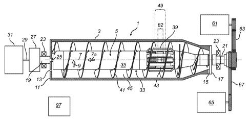
Fig. 1 shows a centrifugal separator or a decanter centrifuge 1
comprising a bowl 3 and a screw conveyor 5 which are mounted such
CA 02763342 2011-11-24
WO 2010/142300 PCT/DK2010/050137
that they in use can be brought to rotate around an axis 7 of rotation ex-
tending in a longitudinal direction 7a of the decanter centrifuge. Further,
the decanter centrifuge 1 has a radial direction 9 extending perpendicu-
lar to the longitudinal direction.
5 For the sake of simplicity directions "up" and "down" are used
herein as referring to a radial direction towards the axis 7 of rotation and
away from the axis 7 of rotation, respectively.
The bowl 3 comprises a base plate 11 provided at one longitudi-
nal end of the bowl 3. The base plate 11 is provided with a number of
light phase outlet openings 13. Furthermore the bowl 3 is at an end op-
posite to the base plate 11 provided with heavy phase outlet openings
15, which are provided next to a flange 17 closing the bowl 3 at the end
opposite the base plate 11. A base shaft 19 is attached to the base plate
11 and second shaft 21 is attached to the flange 17. These two shafts
19, 21 are supported in bearings 23 for rotation of the bowl 3 about the
axis 7 of rotation.
In a manner known per se the base shaft 19 is hollow, and a
conveyor shaft 25 is extending therethrough. The conveyor shaft 25 is
supported relative to the base shaft 19 through a bearing, not shown,
for the screw conveyor 5 to rotate relative to the bowl 3 about the axis 7
of rotation. The base shaft 19 and the conveyor shaft 25 are in a manner
known per se interconnected through an epicyclical gear train 27 and a
mutual rotation of the two shafts 19 and 25 is regulated through a con-
trol shaft 29 by a control motor 31.
The screw conveyor 5 comprises a hub 33 with a cylindrical part
and a generally conical part 37, the two parts 35 and 37 being inter-
connected by broad mutually spaced ribs 39 extending in the longitudi-
nal direction. The hub 33 carries a helical conveyor flight 41 for trans-
porting during use a heavy phase towards the heavy phase outlet open-
30 ings 15. Between the cylindrical part 35 and the conical part 37 of the
hub 33 an inlet chamber or acceleration chamber 43 is provided. Be-
tween the hub 33 and the bowl 3 a separation chamber 45 is provided.
Feed ports 47 (see Fig. 2) are provided between the acceleration cham-
ber 43 and the separation chamber 45, and they are defined in a circum-
CA 02763342 2011-11-24
WO 2010/142300 PCT/DK2010/050137
6
ferential direction 46 by the mutually spaced ribs 39 and in the longitu-
dinal direction by the cylindrical part 35 and the conical part 37 of the
hub 33. Thus the feed ports 47 extend a first axial area 49 (Fig. 2).
Referring to Fig. 2 it is seen that the second shaft 21 extends
into the conical part 37 of the conveyor hub 33 to support the latter ro-
tatably through a bearing 48. A pulley 50 is mounted on the second
shaft 21. A feed pipe 51 extends through the second shaft 21 and the
conical part 37 and is rotatably supported through a bearing 52. A pulley
53 is mounted on the feed pipe 51. A mounting disc 55 is sealingly
mounted in the cylindrical part 35 of the conveyor hub 33. The mounting
disc receives sealingly and releasably a bearing 57 supporting a feed ac-
celerator 59 attached to the feed pipe 51. A feed pipe motor 61 is pro-
vided or driving the feed pipe 51 rotationally through belts 63 and the
pulley 53. Thus the feed pipe 51 may be rotated around the longitudinal
axis 7. A main motor 65 is providing for driving the second shaft 21 ro-
tationally through belts 67 and the pulley 50. Thus the main motor 65
through belts 67, the pulley 50, the second shaft 21, the flange 17, the
bowl 3, the base plate 11, the base shaft 19, the epicyclical gear train 27
and the conveyor shaft 25 provide a first drive for the conveyor, and the
feed pipe motor 61 provide through belts 63, the pulley 53 and the feed
pipe 51 a second drive for the feed accelerator 59.
Referring to Figs. 3 and 4 the feed accelerator 59 comprises a
tubular part 69 welded onto the feed pipe 51 to be integral therewith and
constitute an inlet tube, said tubular part being closed at an end opposite
the feed pipe and carrying an axle journal 71 attached to the bearing 57.
Two discharge ports 73 are provided in the sidewall of the tubular part
69 and two casing elements 75 are mounted on the tubular part 69.
Each casing element comprises a curved wall part 77 extending, when
the casing element is mounted, from one end, in which it is tangential to
the inner side of the sidewall of the tubular part 69. The curved wall part
extends away from the tubular part to a discharge opening 79 defined by
the casing element 75. At the discharge opening 79 the curved wall ex-
tends in the circumferential direction 46. The casing elements further
comprise sidewall parts 81 defining the extend of the discharge openings
CA 02763342 2011-11-24
WO 2010/142300 PCT/DK2010/050137
7
79 in the longitudinal direction. Thus the discharge openings 79 extend a
second axial area 82 situated within the first axial area 49 (see Fig. 2).
The discharge ports 73 and the casing elements 75 together constitute
discharge outlets. The tubular part comprises an axial flange 83 for re-
stricting backflow in a manner known per se.
The casing elements are mounted by means of screws 85 in-
serted through holes in one of the casing elements and screwed into
threaded holes in the other casing element. Pins 87 inserted in holes in
the casing elements 75 and the tubular part 69, respectively secure the
casing elements in correct position relative to the tubular part. Thus the
screws 85 and pins 87 provide a mounting for the exchangeable casing
provided by the casing elements 75.
At an outer end of each casing element and opposite the dis-
charge opening 79 a wear pad 89 is exchangeably mounted by means of
a screw 91.
In use a liquid material e.g. a slurry comprising a light phase
and a heavy phase is fed into the bowl 3 to form a liquid annular body
with an upper surface 93. The annular body, the so-called pond, is rotat-
ing in the circumferential direction 46 at a high speed together with the
bowl 3 and the screw conveyor 5, which are approximately, but not ex-
actly, rotating at the same speed as it is well known to the skilled per-
son. In the instance shown in Fig. 5 the pond substantially submerges
the ribs 39. However the hub 33 should generally not be submerged. It
is thus noted that the upper surface 93 of the pond is at a distance from
the cylindrical part 35 of the hub 33 as shown in Fig. 5.
The slurry is separated in the separation chamber 45 and the
light phase and the heavy phase exit the bowl 3 through the light phase
outlet openings 13 and the heavy phase outlet openings 15, respec-
tively.
Simultaneously slurry, called feed, is fed through the feed pipe
51. From the feed pipe 51 the feed enters the tubular part 69 of the feed
accelerator 59 and it exits the tubular part 69 through the discharge
ports 73. The feed pipe 51 and the feed accelerator 59 are also rotating
in the circumferential direction 46, but approximately at half the angular
CA 02763342 2011-11-24
WO 2010/142300 PCT/DK2010/050137
8
speed of the screw conveyor 5.
Having exited through the discharge ports 73 the feed is en-
gaged by the curved wall parts 77 and is accelerated thereby. The feed
thus flows along the curved wall parts 77 guided by the sidewall parts 81
to exit in the circumferential direction through the discharge openings
79.
It should be noted that the curved walls are curved overall com-
prising a straight part proximal to the tubular part 69 and a curved part
distal from the tubular part 69.
Theoretically the feed will exit the discharge opening 79 at twice
the linear speed of the curved wall part 77 at the discharge opening. Due
to friction etc. the speed of the feed will however be a little lower. Ideally
the feed would exit the discharge opening right onto the upper surface
93 with a circumferential speed equal to that of the upper surface, in or-
der to avoid any turbulence created by the impact of the feed into the
pond. However since a distance is present between the inner side of the
curved wall part 77 at the discharge opening and the upper surface 93
the feed will hit the upper surface at a place of impact 95 with a direction
having a radial component and a circumferential component. Since the
radial distance from the centre, i.e. the axis of rotation 7 to the upper
surface 93 is somewhat larger than the radial distance from the axis of
rotation to the inner surface of the curved wall part 77 at the discharge
opening 79, the linear speed of the upper surface 93 would be larger
than the linear speed of the feed exiting the discharge opening if the ro-
tational speed of the feed accelerator were exactly half the rotational
speed of the screw conveyor 5. Therefore the rotational speed of the ac-
celerator is regulated to a somewhat higher speed.
The decanter centrifuge comprises a control 97, which is con-
nected (not shown) to and controlling the three motors i.e. the main
motor 65 the feed pipe motor 61 and the control motor 31. The control
97 also monitors the power needed to run the respective motors.
Monitoring the overall power needed to run the main motor 65
and the feed pipe motor 61 may be used for determining the optimal ro-
tational speed of the accelerator. If the accelerator runs too slow the
CA 02763342 2011-11-24
WO 2010/142300 PCT/DK2010/050137
9
feed will hit the pond at a circumferential speed lower than that of the
upper surface 93 and the liquid below it, which means that the feed must
be accelerated by the liquid of the pond, and turbulence is created. This
turbulence entails a loss of energy. If the accelerator runs too fast the
feed will hit the pond at a circumferential speed higher than that of the
upper surface 93 and the liquid below it, which means that the feed is
braked by the liquid of the pond, and turbulence is created. This turbu-
lence entails a loss of energy. Further the power consumption of the feed
pipe motor is relatively high and the power consumption of the main
motor is relatively low compared to the former example. At the optimal
rotational speed of the feed accelerator the minimum turbulence is cre-
ated and the overall power consumption is minimal.
As mentioned it is an unwanted situation that the pond sub-
merges the hub 33. Should the situation occur the upper surface 93 will
be raised compared to what is shown in Fig. 5 and at least the wear pad
89 attached to the outside of the curved wall part 77 will dip into the up-
per surface 93. Since the pond like the conveyor 5 rotates at a speed
much higher than the accelerator, a drop of the power needed by the
feed pipe motor 61 will be detected by the control 97, thereby detecting
the unwanted situation.
Since the rotational speed of the screw conveyor 5 is much lar-
ger than that of the feed accelerator 59 the ribs 39 will continuously run
swiftly past the outer ends of the casing elements 75, and since material
from the feed may deposit on the inner surfaces of the ribs there is a
risk of impact between such deposit material and the casing elements
75. Such impact may abrade the wear pad 89 which thus may be worn,
for which reason it is exchangeable.
Due to the construction of the feed pipe and the accelerator
these parts are easily exchanged and/or mounted. Thus for mounting
the feed pipe 51 with the tubular part 69 and the bearing 57 is inserted
through the second shaft 21, and the bearing 57 is received by the
mounting disc 55. Subsequently the casing elements 75 with the pins 87
are inserted through the feed ports 47 to be fastened by means of the
screws 85, which are likewise inserted through the feed ports 47.
CA 02763342 2011-11-24
WO 2010/142300 PCT/DK2010/050137
The invention has mainly been described above with reference
to a few embodiments. However, as is readily appreciated by a person
skilled in the art, other embodiments than the ones disclosed above are
equally possible within the scope of the invention, as defined by the ap-
5 pended patent claims.