Sélection de la langue

Search

Sommaire du brevet 2765395 

Énoncé de désistement de responsabilité concernant l'information provenant de tiers

Une partie des informations de ce site Web a été fournie par des sources externes. Le gouvernement du Canada n'assume aucune responsabilité concernant la précision, l'actualité ou la fiabilité des informations fournies par les sources externes. Les utilisateurs qui désirent employer cette information devraient consulter directement la source des informations. Le contenu fourni par les sources externes n'est pas assujetti aux exigences sur les langues officielles, la protection des renseignements personnels et l'accessibilité.

Disponibilité de l'Abrégé et des Revendications

L'apparition de différences dans le texte et l'image des Revendications et de l'Abrégé dépend du moment auquel le document est publié. Les textes des Revendications et de l'Abrégé sont affichés :

  • lorsque la demande peut être examinée par le public;
  • lorsque le brevet est émis (délivrance).
(12) Brevet: (11) CA 2765395
(54) Titre français: CONNECTEUR EMBOUTI PLEINE TENSION
(54) Titre anglais: FULL TENSION SWAGED CONNECTOR
Statut: Octroyé
Données bibliographiques
(51) Classification internationale des brevets (CIB):
  • H01R 24/38 (2011.01)
  • H01R 4/18 (2006.01)
  • H02G 7/00 (2006.01)
  • H02G 15/08 (2006.01)
(72) Inventeurs :
  • SOSA, LUIS (Etats-Unis d'Amérique)
  • HOBBS, ROBERT (Etats-Unis d'Amérique)
  • YOUNG, BRUCE (Etats-Unis d'Amérique)
(73) Titulaires :
  • DMC POWER, INC. (Etats-Unis d'Amérique)
(71) Demandeurs :
  • DMC POWER, INC. (Etats-Unis d'Amérique)
(74) Agent: RICHES, MCKENZIE & HERBERT LLP
(74) Co-agent:
(45) Délivré: 2014-07-08
(22) Date de dépôt: 2012-01-25
(41) Mise à la disponibilité du public: 2013-07-25
Requête d'examen: 2012-05-30
Licence disponible: S.O.
(25) Langue des documents déposés: Anglais

Traité de coopération en matière de brevets (PCT): Non

(30) Données de priorité de la demande: S.O.

Abrégés

Abrégé français

Un connecteur pleine tension amélioré pour conducteurs électriques comporte une surface externe essentiellement cylindrique et un ensemble en gradins de surfaces internes essentiellement cylindriques présentant des diamètres intérieurs progressivement plus petits. La conception du connecteur permet une régulation améliorée de la compression du câble à l'intérieur du raccord. Un ensemble de cosses, exerçant une compression progressivement plus importante, assurent que le connecteur saura résister à l'effort de tension requis.


Abrégé anglais

An improved full tension connector for electrical conductors has a substantially cylindrical outer surface and a stepped series of substantially cylindrical inner surfaces with progressively smaller inside diameters. The design of the connector allows for improved control of the compression of the cable inside the fitting. A series of swages, progressing successively from a light compression to a heavier compression, ensures that the connector will sustain the required tensile load.

Revendications

Note : Les revendications sont présentées dans la langue officielle dans laquelle elles ont été soumises.


What is claimed is:
1. A connector for an electrical conductor comprising: a body having a
substantially
cylindrical outer surface; a first substantially cylindrical inner surface
having a first inside
diameter d1, the first inner surface extending axially from a first end
of the body to a
depth A; a second substantially cylindrical inner surface having a second
inside diameter
d2 smaller than d1, the second inner surface extending axially from
the depth A
to a depth B; wherein d1-d2 < 0.05".
2. The connector of claim 1 further comprising a third substantially
cylindrical inner
surface having a third inside diameter d3 smaller than d2, the third
inner surface
extending axially from the depth B to a depth C; wherein d2-d3 <
0.05".
3. The connector of claim 2 further comprising a fourth substantially
cylindrical
inner surface having a fourth inside diameter d4 smaller than d3,
the fourth
inner surface extending axially from the depth C to a depth D; wherein d3-

d. sub .4 < 0 .05".
4. The connector of claim 1 wherein the body is configured as a splice.
5. The connector of claim 1 wherein the body is configured as a dead end.
6. A method of attaching the connector of claim 1 to an electrical
conductor
comprising: inserting an electrical conductor into the connector to at least
depth B;
compressing the outer surface of the connector between the first end and depth
A with a
first compression force; compressing the outer surface of the connector
between depth A
and depth B with a second compression force greater than the first compression
force.


7. A method of attaching the connector of claim 2 comprising: inserting an
electrical
conductor into the connector to at least depth B; compressing the outer
surface of the
connector between the first end and depth A with a first compression force;
compressing
the outer surface of the connector between depth A and depth B with a second
compression force greater than the first compression force; and compressing
the outer
surface of the connector between depth B and depth C with a third compression
force
greater than the second compression force.
8. The method of claim 6 wherein the steps of compressing are performed
using a
swaging tool.
9. The method of claim 7 wherein the steps of compressing are perforated
using a
swaging tool.
6

Description

Note : Les descriptions sont présentées dans la langue officielle dans laquelle elles ont été soumises.

CA 02765395 2012-01-25
FULL TENSION SWAGED CONNECTOR
BACKGROUND OF THE INVENTION
FIELD OF THE INVENTION
[0001] This invention relates to the field of power transmission and, more
particularly, to
connectors for high tension power transmission lines.
BACKGROUND
[0002] Connectors play a critical role in the efficiency and reliability of
power transmission
systems. Aluminum cables used for overhead transmission lines require
connectors for splices
and dead end assemblies. Currently available connectors are typically tubular
aluminum devices
that are crimped or swaged onto the cable. In order to achieve a full or
nearly full tension fitting,
prior art connectors require numerous crimps or swages and are therefore
relatively long and
heavy. In addition, the installation tools for prior art connectors are large
and unwieldy. During
the installation of prior art connectors, the length of the fitting and the
size of the tooling may
result in undesired bending of the connector.
SUMMARY OF INVENTION
[0003] The present invention provides an improved connector with a body
having a
substantially cylindrical outer surface and a stepped series of substantially
cylindrical inner
surfaces with progressively smaller inside diameters. The design of the
connector allows for
improved control of the compression of the cable inside the fitting. A series
of swages,
1

CA 02765395 2012-01-25
progressing successively from a light compression to a heavier compression,
ensures that the
connector will sustain the required tensile load.
[0004] In comparison to prior art connectors, the present invention
provides a smaller, lighter
full tension connector that can be installed with fewer swages. Installation
of the connector is
quicker and easier than prior art counterparts. Furthermore, the connector is
less prone to
bending during installation.
BRIEF DESCRIPTION OF THE DRAWINGS
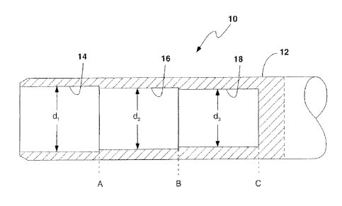
[0005] Figure 1 is a partial cross-sectional view of a connector in
accordance with an
embodiment of the present invention.
DETAILED DESCRIPTION OF THE INVENTION
[0006] In the following description, for purposes of explanation and not
limitation, specific
details are set forth in order to provide a thorough understanding of the
present invention.
However, it will be apparent to one skilled in the art that the present
invention may be practiced
in other embodiments that depart from these specific details. In other
instances, detailed
descriptions of well-known methods and devices are omitted so as to not
obscure the description
of the present invention with unnecessary detail.
[0007] A connector 10 in accordance with one embodiment of the present
invention is shown
in Figure 1. The connector body 12 has a substantially cylindrical outer
surface. A first
substantially cylindrical inner surface 14 has an inside diameter d1 and
extends axially from the
end of connector body 12 to a depth A. A second substantially cylindrical
inner surface 16 has
2

CA 02765395 2012-01-25
an inside diameter d2, which is smaller than d1, and extends axially from
depth A to depth B. A
third substantially cylindrical inner surface 18 has an inside diameter d3,
which is smaller than
d2, and extends axially from depth B to depth C.
[0008] To install the connector 10 onto a cable, the end of the cable is
inserted into the
connector body to depth C. The connector is compressed onto the cable using a
hydraulic
swaging tool. A suitable swaging tool may be, for example, the tool disclosed
in U.S. Patent No.
7,299,674 and commercially available under the CableLok brand from Designed
Metal
Connections of Gardena, California. The design of connector 10 allows it to be
installed on the
cable using a single die set.
[0009] The first swage area at the end of the connector (i.e., between the
end of the
connector body where the cable is inserted and depth A) carries the maximum
load. This has the
minimum compression, thereby minimizing damage to the cable. The second swage
area (i.e.,
between depth A and depth B) holds the load that the first swage area cannot
take and has a
heavier compression to provide better electrical contact. The third swage area
(i.e., between
depth B and depth C) carries less load, but provides the best electrical
contact. When properly
installed, connector 10 can sustain a load of 95% or more of the rated
strength of the cable,
thereby meeting the requirements for class 1 full tension fittings of the
C119.4 ANSI standard.
[0010] As will be appreciated, the specific dimensions of connector 10 are
dependent upon
the dimensions of the cable with which it will be used. The smallest inside
diameter, in this case
d3, is slightly greater than the nominal outside diameter of the cable. The
inside diameter step
sizes (i.e., the difference between d1 and d2 and the difference between d2
and d3) may be less
than about 0.05 inches. The axial length of each step (i.e., the distance from
the end of the
3

CA 02765395 2012-01-25
connector body to depth A, from depth A to depth B, and from depth B to depth
C) is determined
primarily by the dimensions of the swaging tool head and may be approximately
1 inch.
Connector 10 has been described as having three swaging segments; however, it
is to be
understood that other embodiments of the invention may have more or fewer
segments.
[0011] Connector 10 may be configured either as a splice connector with a
tubular body
receiving a cable at each end or as a full tension dead end having a suitable
structural coupling.
In one embodiment, connector 10 is fabricated with 6061-T6 aluminum alloy,
although other
alloys may be used. In this embodiment, the connector body is heat treated
(annealed) after
machining.
[0012] It will be recognized that the above-described invention may be
embodied in other
specific forms without departing from the spirit or essential characteristics
of the disclosure.
Thus, it is understood that the invention is not to be limited by the
foregoing illustrative details,
but rather is to be defined by the appended claims.
4

Dessin représentatif
Une figure unique qui représente un dessin illustrant l'invention.
États administratifs

Pour une meilleure compréhension de l'état de la demande ou brevet qui figure sur cette page, la rubrique Mise en garde , et les descriptions de Brevet , États administratifs , Taxes périodiques et Historique des paiements devraient être consultées.

États administratifs

Titre Date
Date de délivrance prévu 2014-07-08
(22) Dépôt 2012-01-25
Requête d'examen 2012-05-30
(41) Mise à la disponibilité du public 2013-07-25
(45) Délivré 2014-07-08

Historique d'abandonnement

Il n'y a pas d'historique d'abandonnement

Taxes périodiques

Dernier paiement au montant de 347,00 $ a été reçu le 2024-01-19


 Montants des taxes pour le maintien en état à venir

Description Date Montant
Prochain paiement si taxe générale 2025-01-27 347,00 $
Prochain paiement si taxe applicable aux petites entités 2025-01-27 125,00 $

Avis : Si le paiement en totalité n'a pas été reçu au plus tard à la date indiquée, une taxe supplémentaire peut être imposée, soit une des taxes suivantes :

  • taxe de rétablissement ;
  • taxe pour paiement en souffrance ; ou
  • taxe additionnelle pour le renversement d'une péremption réputée.

Les taxes sur les brevets sont ajustées au 1er janvier de chaque année. Les montants ci-dessus sont les montants actuels s'ils sont reçus au plus tard le 31 décembre de l'année en cours.
Veuillez vous référer à la page web des taxes sur les brevets de l'OPIC pour voir tous les montants actuels des taxes.

Historique des paiements

Type de taxes Anniversaire Échéance Montant payé Date payée
Le dépôt d'une demande de brevet 400,00 $ 2012-01-25
Requête d'examen 800,00 $ 2012-05-30
Enregistrement de documents 100,00 $ 2012-11-08
Taxe de maintien en état - Demande - nouvelle loi 2 2014-01-27 100,00 $ 2014-01-08
Taxe finale 300,00 $ 2014-04-15
Taxe de maintien en état - brevet - nouvelle loi 3 2015-01-26 100,00 $ 2015-01-19
Taxe de maintien en état - brevet - nouvelle loi 4 2016-01-25 100,00 $ 2016-01-18
Taxe de maintien en état - brevet - nouvelle loi 5 2017-01-25 200,00 $ 2017-01-23
Taxe de maintien en état - brevet - nouvelle loi 6 2018-01-25 200,00 $ 2018-01-22
Taxe de maintien en état - brevet - nouvelle loi 7 2019-01-25 200,00 $ 2019-01-21
Taxe de maintien en état - brevet - nouvelle loi 8 2020-01-27 200,00 $ 2020-01-17
Taxe de maintien en état - brevet - nouvelle loi 9 2021-01-25 204,00 $ 2021-01-15
Taxe de maintien en état - brevet - nouvelle loi 10 2022-01-25 254,49 $ 2022-01-21
Taxe de maintien en état - brevet - nouvelle loi 11 2023-01-25 263,14 $ 2023-01-20
Taxe de maintien en état - brevet - nouvelle loi 12 2024-01-25 347,00 $ 2024-01-19
Titulaires au dossier

Les titulaires actuels et antérieures au dossier sont affichés en ordre alphabétique.

Titulaires actuels au dossier
DMC POWER, INC.
Titulaires antérieures au dossier
S.O.
Les propriétaires antérieurs qui ne figurent pas dans la liste des « Propriétaires au dossier » apparaîtront dans d'autres documents au dossier.
Documents

Pour visionner les fichiers sélectionnés, entrer le code reCAPTCHA :


Pour visualiser une image, cliquer sur un lien dans la colonne description du document. Pour télécharger l'image (les images), cliquer l'une ou plusieurs cases à cocher dans la première colonne et ensuite cliquer sur le bouton "Télécharger sélection en format PDF (archive Zip)" ou le bouton "Télécharger sélection (en un fichier PDF fusionné)".

Liste des documents de brevet publiés et non publiés sur la BDBC .

Si vous avez des difficultés à accéder au contenu, veuillez communiquer avec le Centre de services à la clientèle au 1-866-997-1936, ou envoyer un courriel au Centre de service à la clientèle de l'OPIC.


Description du
Document 
Date
(yyyy-mm-dd) 
Nombre de pages   Taille de l'image (Ko) 
Abrégé 2012-01-25 1 12
Description 2012-01-25 4 138
Revendications 2012-01-25 2 55
Dessins 2012-01-25 1 9
Page couverture 2013-07-29 1 35
Dessins représentatifs 2013-06-27 1 8
Page couverture 2014-06-12 1 35
Poursuite-Amendment 2012-11-08 2 45
Cession 2012-01-25 3 109
Poursuite-Amendment 2012-05-30 1 52
Cession 2012-11-08 11 477
Correspondance 2014-04-15 1 55
Taxes 2014-01-08 1 51