Note : Les descriptions sont présentées dans la langue officielle dans laquelle elles ont été soumises.
CA 02765596 2011-12-14
WO 2010/146500 PCT/IB2010/052562
1
DIMMABLE LIGHT SOURCE WITH LIGHT TEMPERATURE SHIFT
FIELD OF THE INVENTION
The present invention relates in general to an illumination device comprising
LEDs as light sources.
BACKGROUND OF THE INVENTION
The use of LEDs as light source for illumination rather than mere indicator
lights is well known, since the development of high-power LEDs. It is also
rather standard
that an illumination device is powered from mains, typically 230 V @ 50 Hz in
Europe.
Since LEDs require a relatively low voltage (typically in the order of 3 V)
and allow current
flow in one direction only, driver circuits have been developed for generating
a DC LED
current on the basis of the AC mains. However, such driver circuits are
relatively expensive.
In a more simple approach, a string of LEDs is connected to mains directly, in
series with a ballast resistor. For allowing LED current and thus light output
in both halves of
the AC period, two such strings are connected anti-parallel. The idea would be
that, for
instance, 70 LEDs would accommodate a voltage drop of 210 V, while the
remaining 20 V
would be accommodated by the ballast resistor. Voltage variations would be
taken up by the
ballast resistor.
Although the simplicity of this approach, and hence the relatively cheap
implementation thereof, has a certain attractiveness, there is a problem when
it is desired that
the illumination device is dimmed.
For certain applications, it is not only desired that the illumination device
is
dimmable, but also that the color temperature of the output light is shifted
to a lower value on
dimming. This requirement is specifically important in the case of small
bedside lamps or
reading lamps, but it may be that there are other applications where the same
feature would
be desirable.
SUMMARY OF THE INVENTION
An object of the present invention is to provide a simple and cost-efficient
illumination device having a plurality of LEDs as light sources, capable of
being dimmed in a
CA 02765596 2011-12-14
WO 2010/146500 PCT/IB2010/052562
2
simple manner while simultaneously the light output of the device shifts to a
lower color
temperature automatically.
According to an important aspect of the present invention, a power source for
an illumination device comprises an autotransformer with two outputs. A first
part of the
LEDs are coupled to the first output, while the second part of the LEDs are
coupled to the
second output. Changing the setting of the autotransformer automatically
changes the ratio of
the output voltages and therefore the color temperature of the light output as
a whole.
Further advantageous elaborations are mentioned in the dependent claims.
BRIEF DESCRIPTION OF THE DRAWINGS
These and other aspects, features and advantages of the present invention will
be further explained by the following description of one or more preferred
embodiments with
reference to the drawings, in
figure 1 schematically shows a block diagram of an illumination device;
figure 2 schematically shows a block diagram of a preferred embodiment of a
voltage source, comprising an autotransformer.
DETAILED DESCRIPTION OF THE INVENTION
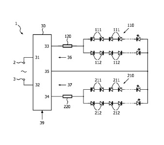
Figure 1 schematically shows a block diagram of an illumination device 1
according to the present invention. The illumination device 1 comprises input
terminals 2, 3
for coupling to AC mains. The illumination device further comprises a voltage
source 30
having two input terminals 31, 32 connected to the input terminals 2, 3 of the
illumination
device 1, and having three output terminals 33, 34, 35. These output terminals
define two
outputs of the voltage source 30, one of these terminals, in this case the
central terminal 35,
being a common terminal. More particularly, a first output terminal 33
together with the
common output terminal 35 defines a first output 36 for connecting a load, and
a second
output terminal 34 together with the common output terminal 35 defines a
second output 37
for connecting a load.
A first string 110 of LEDs is connected in series with a first resistor 120,
and
this series arrangement is connected to the first output 36 of the voltage
source 30. This first
LED string 110 comprises a first series arrangement of power LEDs 111 and a
second series
arrangement of power LEDs 112 connected anti-parallel to the first series
arrangement. The
number of LEDs in these series arrangements is not important for understanding
the present
invention.
CA 02765596 2011-12-14
WO 2010/146500 PCT/IB2010/052562
3
Similarly, a second string 210 of LEDs is connected in series with a second
resistor 220, and this series arrangement is connected to the second output 37
of the voltage
source 30. This second LED string 210 comprises a third series arrangement of
power LEDs
211 and a fourth series arrangement of power LEDs 212 connected anti-parallel
to the third
series arrangement.
The LEDs 111, 112, 211, 212 are mounted close together in the illumination
device 1, so that the overall output light as produced by the illumination
device 1 as a whole,
as perceived by a user, is a mixture of the individual light outputs of the
individual LEDs
111, 112, 211, 212.
Typically, the LEDs 111, 112 of the first LED string 110 are preferably white
power LEDs. However, it is also possible that one or more of these LEDs are
colored LEDs.
In any case, the design of the first series arrangement of LEDs 111 is
preferably identical to
the design of the second series arrangement of LEDs 112, in that they mutually
have the
same number of LEDs of a specific color.
Typically, the LEDs 211, 212 of the second LED string 210 are preferably red
power LEDs. However, it is also possible that one or more of these LEDs have
different
colors. In any case, the design of the third series arrangement of LEDs 211 is
preferably
identical to the design of the fourth series arrangement of LEDs 212, in that
they mutually
have the same number of LEDs of a specific color.
In any case, the design of the third/fourth series of LEDs differs from the
design of the first/second series of LEDs.
It is noted that the gist of the present invention is also applicable if the
color of
the second LED string 210 has a lower color temperature than the color of the
first LED
string 110. For instance, an embodiment would be possible where the first LED
string 110
has white LEDs while the second LED string 210 has orange or yellow LEDs.
The voltage source 30 is designed so that the voltage difference between the
first and second output terminals 33, 34 is always constant while the voltage
at the common
output terminal 35 can be varied in the range between the voltage of the first
output terminal
33 and the voltage of the second output terminal 34. Figure 2 is a block
diagram
schematically illustrating an embodiment of the voltage source 30 that has the
advantage of
structural simplicity. In this embodiment, the voltage source 30 comprises an
autotransformer
300. Since autotransformers are known per se, a detailed explanation is not
needed. In
general, the autotransformer 300 comprises a single winding 310 having five
taps 301, 302,
303,304,305.
CA 02765596 2011-12-14
WO 2010/146500 PCT/IB2010/052562
4
A first tap 301 of the autotransformer 300 is connected to the first input
terminal 31 of the voltage source 30.
A second tap 302 of the autotransformer 300 is connected to the second input
terminal 32 of the voltage source 30.
A third tap 303 of the autotransformer 300 is connected to the first output
terminal 33 of the voltage source 30.
A fourth tap 304 of the autotransformer 300 is connected to the second output
terminal 34 of the voltage source 30.
These taps 301, 302, 303, 304 are fixed taps; thus, it will be clear that the
output voltage between the first output terminal 33 and the second output
terminal 34 of the
voltage source 30 always has the same value as long as the input voltage
remains constant. In
a preferred embodiment, the third tap 303 coincides with the first tap 301 and
the fourth tap
304 coincides with the second tap 302, but this is not essential for
understanding the present
invention.
A fifth tap 305 of the autotransformer 300 is connected to the common output
terminal 35 of the voltage source 30. This fifth tap 305 is a displaceable
tap, displaceable
along the length of the transformer winding, so that the voltage at this tap
varies in
accordance with its position. The position of the displaceable tap can be
adjusted by a user,
for instance by handling a knob or wheel or handle (not shown) attached to the
tap. Such
knob or handle has the function of a user input 39 (see figure 1).
Assume that the first string 110 consists of white LEDs 111, 112 while the
second string 210 consists of red LEDs 211, 212. When the user manipulates the
user input
39 so that the voltage at the common output terminal 35 is equal to the
voltage at the second
output terminal 34 (fifth tap 305 moved towards to lower end in figure 2), the
full output
voltage is applied over the first string 110 of LEDs 111, 112 in series with
the first resistor
120. Thus, the current in this string is at a maximum, and the light output is
bright white
light.
As the user manipulates the user input 39 so that the fifth tap 305 moves away
from the lower end of the winding to the upper end of the winding, the voltage
at the
common output terminal 35 approaches the voltage at the first output terminal
33 so that the
voltage over the first output 36 decreases while at the same time the voltage
over the second
output 37 increases. Thus, the light level of the white output light is
reduced while at the
same time the light level of the red output light increases. With a proper
design of the series
resistors 120 and 220, the overall result will be that the light output level
of the illumination
CA 02765596 2011-12-14
WO 2010/146500 PCT/IB2010/052562
device is reduced (dimmed), while the relative content of red light in the
output light is
increased (shift to lower color temperature).
It is noted that, instead of a controllable voltage source 40, a controllable
current source can be used, designed such that the total current remains
constant when the
5 current at one output is increased/decreased.
Summarizing, the present invention provides an illumination device 1
comprising mains input terminals 2, 3 and a power source 30, having input
terminals 31, 32
coupled to the mains input terminals and having three having output terminals
33, 35, 34, one
of said output terminals being a common output terminal 35. A first output 36
is defined by a
first output terminal and said common output terminal; a second output 37 is
defined by a
second output terminal and said common output terminal.
A first LED string 110 is connected to the first power source output in series
with a first resistor 120.
A second LED string 210 is connected to the second power source output in
series with a second resistor 220.
The power source is controllable to vary the voltage at the common output
terminal within the range from the voltage at the first output terminal to the
voltage at the
second output terminal.
While the invention has been illustrated and described in detail in the
drawings
and foregoing description, it should be clear to a person skilled in the art
that such illustration
and description are to be considered illustrative or exemplary and not
restrictive. The
invention is not limited to the disclosed embodiments; rather, several
variations and
modifications are possible within the protective scope of the invention as
defined in the
appending claims. For instance, each LED string may have a configuration
differing from the
configuration shown in figure 1. For example, the LED string may be
implemented as a
series arrangement of LED units, wherein each LED unit comprises at least one
first LED
connected anti-parallel to at least one second LED. Other ladder
configurations are
conceivable, too. Further, it is not necessary that a string has anti-parallel
LEDs: if a string is
provided with a bridge rectifier (not shown) or other type of rectifier, the
string may consist
of one-directional LEDs only, which may offer a saving in product count.
Other variations to the disclosed embodiments can be understood and effected
by those skilled in the art in practicing the claimed invention, from a study
of the drawings,
the disclosure, and the appended claims. In the claims, the word "comprising"
does not
exclude other elements or steps, and the indefinite article "a" or "an" does
not exclude a
CA 02765596 2011-12-14
WO 2010/146500 PCT/IB2010/052562
6
plurality. The mere fact that certain measures are recited in mutually
different dependent
claims does not indicate that a combination of these measures cannot be used
to advantage.
Any reference signs in the claims should not be construed as limiting the
scope.