Note : Les descriptions sont présentées dans la langue officielle dans laquelle elles ont été soumises.
CA 02768786 2014-06-27
54106-1002
1
Lifting Fitting
FIELD OF THE INVENTION
The invention describes a lifting fitting for use in lifting
a series of elements of different sizes. The invention fur-
ther describes a method of assembling a series of elements of
different sizes. The invention also describes the use of a
lifting fitting in the assembly of a tower.
BACKGROUND
Many wind turbines are constructed as hollow steel towers
made of prefabricated tower sections. The tower sections,
which are generally made of steel and may be several tens of
metres in length and several metres in diameter, may be manu-
factured at one location and then transported horizontally by
rail, ship, etc. to their destination location. To prevent
damage during transport, the tower sections are generally se-
cured using some suitable type of fixture, as described in WO
2007/093854 A2 and US 2005/0002749 Al. These fixtures make
use of the end flanges of each tower section to secure the
tower sections to a transport frame or container. Once the
tower sections have arrived at their end destination, the
tower is constructed or assembled by successively lifting and
placing a series of tower sections on top of each other,
whereby the lowest tower section is mounted on a foundation,
usually made of concrete, and includes access means such as a
doorway to later allow access for a maintenance crew. The
tower sections become successively smaller in diameter to-
wards the top of the tower. Neighbouring tower sections are
connected together by means of fasteners such as construction
bolts inserted into connection holes in the end flanges. For
example, for a pair of tower sections comprising a 'lower'
tower section and an 'upper' tower section, the connection
holes of the neighbouring sections are positioned such that
connection holes in the top flange of the lower tower section
match the connection holes in the bottom flange of the upper
tower section.
CA 02768786 2014-06-27
54106-1002
2
To lift a tower section, a number of lifting fittings - usu-
ally at least two - is mounted to one of the end flanges of
the section, usually the upper flange, and a cable is con-
nected to the lifting fittings to allow a crane to hoist the
section onto the previously assembled partial tower. However,
the successive tower sections differ in diameter owing to the
overall conical tower shape, and the spacings between the
connection holes therefore also differ. To accommodate these
differences, prior art lifting techniques have required mul-
tiple lifting fittings, sometimes even a specific lifting
fitting for each tower section.
In one approach, WO 2008/000262 Al describes a lifting fit-
ting designed to be adapted to tower sections of different
diameters. In this approach, the adjustability is given by a
pair of large openings in the lifting fitting, and a number
of sleeves which can be rotated about a fastener inserted
through the opening. For stability, this lifting fitting is
equipped with an additional strut which must be screwed into
place. Furthermore, to ensure that the sleeves do not move
during the lifting procedure, the sleeves must be= fixed to
each bolt by means of a grub screw. While =this approach al-
lows the use of a single type of lifting fitting, this fit-
ting requires the use of multiple sleeves, and the process of
connecting such fittings to each tower section and then dis-
connecting them again is extremely time-consuming. The rela-
tively large number of small parts - sleeves, struts, grub
screws, etc. - can result in problems if a part is dropped or
mislaid. Furthermore, since outdoor construction sites are
exposed to all kinds of weather conditions, the small parts
may become encrusted with dirt or salt over time, so that
they may become jammed or blocked.
SUMMARY
It is therefore an object of some embodiments of the invention
to provide a simple lifting fitting which avoids the problems
outlined above.
CA 02768786 2014-06-27
54106-1002
3
The lifting fitting described herein, for use in lifting a series of
elements of different sizes, comprises a base plate, which
base plate comprises at least one central slotted hole shaped
to accommodate a fastener for fastening the lifting fitting
to an element to be lifted, and at least two outer slotted
holes each shaped to accommodate a further fastener for fas-
tening the lifting fitting to the element to be lifted,
whereby the outer slotted holes are arranged transverse to
the central slotted hole and wherein an outer slotted hole is
positioned in the base plate such that a longitudinal axis of
the outer slotted hole essentially follows the outline of the
element to be lifted. The lifting fitting further comprises a
connection means for connecting the lifting fitting to a
lifting apparatus for lifting the element.
Here, the term 'longitudinal axis' is to be understood to
mean an axis along the length of the slotted hole (viewed
from above), and may be, for example, a longitudinal bisector
of the slotted hole. In the case of circular elements to be
lifted and connected, the outer slotted holes may be slightly
curved, or they may simply be arranged at an angle to the
central slotted hole, for example to point slightly 'inward'.
The favourable arrangement of the slotted holes allows the
lifting fitting to be attached to elements with a
wide range of sizes. In the case of circular elements, the
lifting fitting can be used to lift into place any element
with a diameter in a wide range of diameters. An obvious ad-
vantage of the lifting fitting according to some embodiments of the
invention is that it comprises essentially only one piece. Also, the
lifting fitting itself does not require any adjustment before at-
taching it to an element to be lifted. Therefore, the assem-
bly process can be completed faster. Furthermore, since the
lifting fitting does not require any precisely milled parts
CA 02768786 2014-06-27
54106-1002
4
such as grub screws or threads, its manufacture is particu-
larly economical and straightforward.
In the method according to some embodiments of the invention of
assembling a series of elements of different sizes wherein the
elements are successively lifted into place, the method comprises
fastening such a lifting fitting to an element to be lifted, con-
necting a lifting apparatus to the connecting means of the
lifting fitting, controlling the lifting apparatus to lift
the element onto a predecessor element, and subsequently dis-
connecting the lifting apparatus from the connecting means of
the lifting fitting.
In contrast to prior art lifting fittings, the method accord-
ing to some embodiments of the invention is particularly straight-
forward and fast. Since there are no small parts such as sleeves,
grub screws etc. to be dismantled, the lifting fitting according to
some embodiments of the invention can very quickly be connected to
an element to be lifted, and can equally quickly be removed again.
According to some embodiments of the invention, such a lifting fitting
is used in the assembly of a tower comprising individually liftable
tower sections, preferably for lifting into place a plurality
of tower sections of a wind turbine tower.
30 The lifting fitting according to some embodiments of the invention can
be used to lift any elements of any shape. Usually, however, for con-
struction projects involving a series of connected elements,
the elements will have a cross-section of regular shape, for
example a circle in the case of a tower section. Therefore,
in a particularly preferred embodiment of the invention, the
lifting fitting is dimensioned according to an element with a
circular cross-section, for example a hollow element having
an essentially circular perimeter wall.
PCT/EP 2009/067 714 - 27-09-2010
= 2009P12810W0 CA 02768786 2012-01-20
- 5
. .
-
Preferably, the slotted holes of the lifting fitting corre-
spond to holes or openings in an assembly means of the ele-
ment to be lifted. In the case of a wind turbine tower sec-
tion or other essentially circular element, an assembly means
can be an end flange. Successive pairs of elements can be
fastened together by means of fasteners such as bolts in-
serted through matching openings in the end flanges. Prefera-
bly, the slotted holes of the lifting fitting are dimensioned
according to the holes in the assembly means of the elements
to be lifted. Therefore, in a further preferred embodiment of
the invention, the slotted holes are each dimensioned to ac-
commodate a bolt, preferably a threaded bolt, with a size of
at least 24 mm, more preferably an M24 bolt according to the =
ISO metric standards for fasteners. The portion of the bolt
shaft that is contained within the lifting fitting and the
flange of the elements to be lifted need not be threaded,
since only the end of the bolt that protrudes will be covered
by a corresponding nut, for example.
The slotted holes can be arranged relative to one another in
a number of ways. In this context, the term "transverse" can
mean that an outer slotted hole is arranged at an angle to a
central slotted hole. For example, a pair of outer slotted
holes can be arranged one on each side of one or more central
slotted holes, such that the outer slotted holes slant
slightly 'inwards', i.e. 'into' the element being lifted. The
choice of position for the slotted holes may depend largely
on the spacings between the holes in the assembly means, and
on the extent to which these spacings vary between the
smaller and larger elements to be lifted.
The elements of a series of elements to be lifted may be es-
sentially the same in shape, and may differ only in their
relative sizes. For example, a series of circular elements to
be lifted may all have the same overall design, while each
element is a different size. To connect neighbouring pairs of
elements, it is necessary that the holes for the fasteners be
AMENDED SHEET
PCT/EP 2009/067 714 - 27-09-2010
= 2009P12810W0 CA 02768786 2012-01-20
6
=
arranged appropriately on the top of the 'lower' element and
the bottom of the 'upper' element. Evidently, for different
pairs of neighbouring elements, the spacings between the
holes may also be different. For example, a pair of large
elements may be connected using fasteners inserted through
holes spaced apart by a first, larger distance. A pair of
small elements may be connected using fasteners inserted
through holes spaced apart by a second, smaller distance.
Furthermore, the pair of large elements may require more fas-
teners than the pair of small elements, and may therefore
have a correspondingly larger number of holes. For example,
for a wind turbine tower with a largest diameter of about 5 m
and a smallest diameter of about 2.3 m, the lowest pair of
tower sections or elements may be joined using about 140 fas-
teners spaced apart by about 11 cm, while the top pair is
joined using only about 45 fasteners spaced apart by about 16
cm.
As already indicated above, the slotted holes can be arranged
relative to each other in a number of ways. For example, one
central slotted hole might be placed to essentially follow
the perimeter of the element to be lifted, and the outer
slotted holes might be arranged transversely or perpendicu-
larly to the central slotted hole. However, such an arrange-
ment may be limited to a restricted hole spacing range of the
assembly means of the elements or objects to be lifted.
Therefore, in a preferred embodiment of the invention, the
central slotted hole of the lifting fitting is arranged to
extend along a radius of the element to be lifted. In this
way, the lifting fitting is given a certain amount of 'play'
along the direction of the radius of the element after a fas-
tener has been inserted into the central slotted hole. Since
the outer slotted holes are arranged transverse to the cen-
tral slotted hole, these may essentially follow the perimeter
= 35 of the element to be lifted.
The slotted holes are preferably positioned in the base plate
to coincide with connection holes of the element to be lifted
AMENDED SHEET
PCT/EP 2009/067 714 - 27-09-2010
2009212810W0 CA 02768786 2012-01-20
7
such that a fastener can be inserted through a slotted hole
into a connection hole to connect the lifting fitting to the
element. Here, the term 'coincide' is to be understood to
mean that when the lifting fitting is placed on the element
to be lifted, a connection hole is accessible through each of
the slotted holes through which a fastener is to be inserted.
Evidently, since the slotted holes are larger in area than a
connection hole, these will also expose areas adjacent to the
connection holes. The required dimensions of the slotted
holes can be determined by considering, for example, the
range of diameters of the elements to be lifted and the spac-
ings between the connection holes on each of these elements.
Optimal shapes for the slotted holes can then be determined.
The lifting fitting may have any suitable number of central
slotted holes and outer slotted holes, and the number of
slotted holes can also be influenced by the range of element
sizes involved. For example, a pair of central slotted holes
can be arranged essentially in the centre of the lifting fit-
ting, and can be flanked by an outer slotted hole on each
side. In a particularly preferred embodiment of the lifting
fitting according to the invention, the lifting fitting com-
prises a single central slotted hole and two outer slotted
holes arranged one on each side of the central slotted hole.
Since the lifting fitting itself will be quite heavy, addi-
tional connecting means are preferably arranged on the lift-
ing fitting to assist during handling. For example, lateral
eyelets can be positioned on the outer sides of the base
plate to allow the lifting fitting to be raised and lowered
easily and safely using a crane. In the assembly of a wind
turbine tower, the tower sections are transported horizon-
tally to the site. The lifting fitting can be connected to
the crane using a cable passed through the smaller lateral
eyelets, and raised up by the required height (in the order
of a few metres) where a worker can connect it to the element
AMENDED SHEET
PCT/EP 2009/067 714 - 27-09-2010
2009P12810W0 CA 02768786 2012-01-20
8
to be lifted using appropriate fasteners before releasing the
cable.
While a single lifting fitting could conceivably be used to
lift an element into position, the element would not be sus-
pended vertically, so that its placement may be more time-
consuming and possibly also more dangerous. Therefore, in a
preferred embodiment of the method according to the inven-
tion, a pair of lifting fittings is fastened at essentially
diametrically opposed points on an upper side of the element
to be lifted.
The lifting fitting, when used to lift large and heavy ele-
ments, is preferably equipped with some suitable means for
attaching it to a hoisting apparatus such as industrial crane
rigging. Therefore, in a further preferred embodiment of the
invention, the connection means of the lifting fitting pref-
erably comprises an eyelet or other suitable through-opening
in the side wall for connecting a lifting cable or a shackle.
The eyelet is preferably dimensioned to accommodate a cable
or shackle that is large enough to bear the weight of the
largest element to be lifted. The eyelet can preferably be
reinforced by a grommet or other suitable means to reduce
wear on both eyelet and cable or shackle. Once the lifting
fitting has been connected by a worker as described above to
the element to be lifted, a steel cable or other lifting
means can be connected, for example by means of a shackle, to
the lifting fitting through the eyelet. Thereafter, the ele-
ment can be raised up and hoisted into place. Once the ele-
ment is in place, a worker can connect the lower part of this
element to the upper part of a predecessor element and then
proceed to disconnect the lifting fittings.
Usually, a pair of lifting fittings is used in hoisting an
element into place, and these are preferably arranged at op-
posite sides of the element. For optimal load-distribution,
the eyelet or connecting means is preferably located in a
side wall arranged at an angle to the base plate.
AMENDED SHEET
CA 02768786 2014-06-27
54106-1002
9
The lifting fitting according to some embodiments of the
invention can suit any diameter of the series of circular
elements to be lifted. Since the largest elements are also
generally the heaviest, the lifting fitting is preferably
constructed to bear the heaviest load. Therefore, in a further
preferred embodiment of the invention, the lifting fitting
preferably comprises a number of stiffening plates. These can
be incorporated into the overall lifting fitting in any
suitable fashion. For example, suitable stiffening plates may
be welded at essentially right angles to the base plate and the
side wall on either side of the central slotted hole. The
stiffening plates thus provide an additional reinforcement to
the lifting fitting. Since the material of the lifting fitting
may be any kind of suitable steel such as construction steel,
such additional reinforcements can be added at any time. A
lifting fitting that has been used in the past in the assembly
of towers may be 'upgraded' by welding additional stiffening
plates if it is to be used in the future in the assembly of a
larger tower with heavier tower sections.
According to one aspect of the present invention, there is
provided a lifting fitting for lifting an element into a place
in a wind turbine, comprising: a base plate comprising: at
least one central slotted hole shaped to accommodate a fastener
for fastening the lifting fitting to the element; at least two
outer slotted holes each shaped to accommodate a further
fastener for fastening the lifting fitting to the element; and
a connection for connecting the lifting fitting to a lifting
apparatus for lifting the element, wherein the outer slotted
holes are arranged transverse to the central slotted hole, and
wherein each of the outer slotted holes is positioned in the
CA 02768786 2014-06-27
54106-1002
9a
base plate such that a longitudinal axis of each of the outer
slotted holes essentially follows an outline of the element.
According to another aspect of the present invention, there is
provided a method for lifting an element into a place in a wind
turbine, comprising: arranging a lifting fitting comprising a
base plate, wherein the base plate comprises: at least one
central slotted hole shaped to accommodate a fastener for
fastening the lifting fitting to the element; at least two
outer slotted holes each shaped to accommodate a further
fastener for fastening the lifting fitting to the element; and
a connection for connecting the lifting fitting to a lifting
apparatus for lifting the element, wherein the outer slotted
holes are arranged transverse to the central slotted hole, and
wherein each of the outer slotted holes is positioned in the
base plate such that a longitudinal axis of each of the outer
slotted holes essentially follows an outline of the element;
fastening the lifting fitting to the element; connecting the
lifting apparatus to the connection of the lifting fitting;
controlling the lifting apparatus to lift the element onto a
predecessor element; and disconnecting the lifting apparatus
from the connection of the lifting fitting.
BRIEF DESCRIPTION OF THE DRAWINGS
Other objects and features of the present invention will become
apparent from the following detailed descriptions considered in
conjunction with the accompanying drawings. It is to be
understood, however, that the drawings are designed solely for
the purposes of illustration and not as a definition of the
limits of the invention.
CA 02768786 2014-06-27
54106-1002
9b
Fig. 1 shows a prior art lifting fitting;
Fig. 2 shows a first embodiment of a lifting fitting according
to the invention;
Fig. 3 shows the lifting fitting of Fig. 2 connected to a part
to be lifted;
Fig. 4 shows the lifting fitting of Fig. 2 connected to
different sized parts to be lifted;
CA 02768786 2014-06-27
54106-1002
Fig. 5 illustrates the degrees of freedom in placement of the
lifting fitting of Fig. 2;
5 Fig. 6 shows a shackle connected to the lifting fitting of
Fig. 2;
Fig. 7 shows a crane lifting a wind turbine tower element
with the aid of the lifting fitting according to the inven-
10 tion;
Fig. 8 shows a second embodiment of the lifting fitting ac-
cording to the invention;
Fig. 9 shows a third embodiment of the lifting fitting ac-
cording to the invention.
In the drawings, like reference numbers refer to like objects
throughout. Objects in the diagrams are not necessarily drawn
to scale.
DETAILED DESCRIPTION
Fig. 1 shows a prior art lifting fitting 100 as described in
WO 2008/000262 Al, showing clearly the complex arrangement of
parts used in this approach to a universal lifting fitting.
The top part of the diagram shows a side elevation of the
lifting fitting 100 without a bolt, and the bottom section
shows a cross-section with a bolt 110 connecting the lifting
fitting 100 to a tower section 111.
This lifting fitting 100 comprises a base plate 101, a side
wall 102, an eyelet 103 for handling, and an opening 104
through which a shackle can be attached for lifting. To ad-
just for different sizes of circular tower sections, this
lifting fitting 100 has two relatively large openings 114 in
the base plate. The cross-section shows one such opening 114.
The opening 114 is several =times larger than the bolt 110. To
hold the bolt 110, the lifting fitting 100 requires adjusting
sleeves 105, 106 and a bush 107. The larger adjusting sleeve
CA 02768786 2014-06-27
54106-1002
11
105 also has a relatively large opening 115. The smaller
sleeve 106 has a hole to accommodate the bush 107. The
sleeves 105, 106 can be rotated so that the bolt 110, when
inserted, can be positioned through these openings 114, 115
and inserted into a corresponding hole in the part to be con-
nected 111. However, the sleeves must be screwed tight before
the fitting is subject to load, otherwise they would be free
to move and the bolt would be subject to shear stress and may
fail. The necessary tightening is done using grub screws 112,
113 to fix the sleeves 106, 105 respectively. A third attach-
ment point is given by a strut 108, which must be screwed
tight using screws 109.
While this prior art lifting fitting 100 can be attached to
circular tower sections of various different diameters, it
will be clear to the skilled person that attaching this lift-
ing fitting 100 is a time-consuming operation. Not only are
there are large number of parts 105, 106, 107, 108, 109, 112,
113 to be kept track of, the tightening (and subsequent loos-
ening) of the sleeves 105, 106 with grub screws 112, 113 is
awkward and slow. Furthermore, when dismounting the lifting
fitting 100 after connecting one tower section and in prepa-
ration for lifting the next section, there is a danger that
one or more of the relatively small parts 105, 106, 107, 108,
109, 112, 113 is dropped or mislaid, leading to delays in as-
sembly.
Fig. 2 shows a first embodiment of a lifting fitting 10 ac-
cording to the invention. This lifting fitting 10 comprises a
base plate 17 and a side wall 15 with a connecting means 14
in the form of an opening 14 or eyelet 14 for connection to a
shackle and lifting apparatus. A pair of smaller eyelets 16
located at either end of the side wall 15 is used in handling
the fitting 10 during connection to a part to be lifted.
The lifting fitting 10 is shown to
have a first slotted hole 11 and two further slotted holes
12, 13 facing away from the first slotted hole 11. This ar-
PCT/EP 2009/067 714 - 27-09-2010
. 2009P12810W0 CA 02768786 2012-01-20
12
. .
=
rangement allows degrees of freedom in essentially two direc-
tions for bolts inserted through these slotted holes 11, 12,
13.
This is illustrated with the aid of the following figures. In
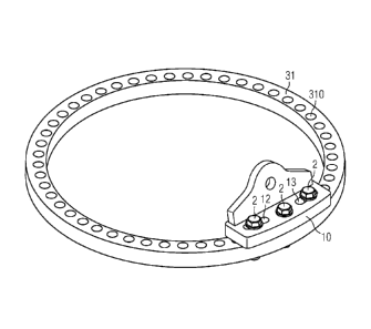
Fig. 3, the lifting fitting 10 is shown connected to an as-
sembly means 31 or flange 31 of a circular tower section. For
the sake of simplicity, only the flange 31 is shown. A series
of holes 310 is arranged around the flange 31 for the bolts
which will connect this tower section to a neighbouring sec-
tion. Six of these holes will be used to attach two lifting
fittings 10 so that the tower section can be raised by a
lifting apparatus onto a foundation or onto another previ-
ously positioned tower section. The diagram shows a single
lifting fitting 10 already in place. Three bolts 2 are used
to connect the lifting fitting 10 to the flange 31. As the
diagram clearly illustrates, no other adapting parts are re-
quired. The bolts can be fastened on the underside of the
flange in the usual manner using appropriate nuts (not shown
in the diagram). The favourable arrangement of the slotted
holes 11, 12, 13 with respect to each other is sufficient to
allow enough 'play' for the bolts to be inserted into the ap-
propriate flange holes 310.
Fig. 4 shows that a single lifting fitting 10, without re-
quiring any additional adjusting parts, can be used for a
wide range of flange sizes. The larger flange 31 (correspond-
ing to a lower tower section) has a radius R1 of 2.5 m and an
arrangement of holes 310 spaced apart by a distance d1 of 15
cm. A smaller flange 39 (corresponding to an upper tower sec-
tion) has a radius R9 of 1.25 m and an arrangement of holes
390 spaced apart by a distance d9 of 14 cm. Obviously, the
curvature of the smaller flange 39 is more pronounced and the
holes 390 are spaced closer together. The lifting fitting 10
can accommodate these differences on account of the favour-
able arrangement of the slotted holes 11, 12, 13. For the
larger flange 31, the bolts 2 are inserted into three
neighbouring holes 310, as indicated on the left-hand side of
AMENDED SHEET
PCT/EP 2009/067 714 - 27-09-2010
' 2009P12810W0 CA 02768786 2012-01-20
- 13
_ .
the flange 31 for the placement of a diametrically opposite
second lifting fitting 10. For the smaller flange 39, the
bolts 2 are inserted through alternate holes 390, as indi-
cated on the left-hand side of the flange 39 for the place-
ment of a second lifting fitting for the small flange 39. As
can be seen in the diagram, even though the lifting fitting
is relatively small compared to the large flange 31 and
relatively large compared to the size of the small flange 39,
the favourable placement of the slotted holes in the base
10 plate of the lifting fitting 10 allow this to be easily and
securely connected to the different sized flanges 31, 39.
Fig. 5 illustrates the degrees of freedom in placement of the
lifting fitting 10. Here, the fitting 10 is viewed from be-
low, and three bolts 2 are shown to be inserted through the
slotted holes 11, 12, 13. The bolt 2 in the central slotted
hole 11 is free to move in the direction DR, which corre-
sponds to a radial direction, i.e. to a radius of the circu-
lar part to which this fitting 10 can be connected. The bolts
2 in the outer slotted holes 12, 13 are free to move in the
directions DTI, DT2 respectively, i.e. tangentially to a cir-
cumference or perimeter of the circular part. The diagram
also shows that the bolts 2 in the outer slotted holes 12, 13
need not be placed symmetrically, i.e. one bolt 2 can be
placed towards the centre of the fitting 10, while the other
bolt 2 is placed further outward. Obviously, any combination
of positions for the bolts 2 in the three holes 11, 12, 13 is
permissible, and the actual arrangement will depend only on
the dimensions (radius, hole separation) of the part to be
lifted. The range in hole spacings which can be dealt with by
this lifting fitting 10 is bounded by the smallest distance
and the largest distance between two bolts inserted into two
of the slotted holes 11, 12, 13. In this embodiment, there-
fore, the smallest conceivable distance is given by Drain, when
one bolt is placed into the central slotted hole 11, and a
second bolt is placed in one of the outer slotted holes 12,
13 at the end closest to the central slotted hole 11. The
largest conceivable distance is given by Na., when two bolts
AMENDED SHEET
CA 02768786 2014-06-27
54106-1002
14
are placed into the outermost ends of the outer slotted holes
12, 13. Depending on the weight of the element to be lifted,
these distances Dmint Dmax can effectively be doubled by plac-
ing bolts into the inner corners of the outer slotted holes
12, 13 only, or into the outer corners of the outer slotted
holes 12, 13 respectively. Whether this latter arrangement
would be used would depend very much on the weight of the ob-
ject being lifted. Another important aspect of the lifting
fitting 10 is shown here, namely
that the slotted holes 11, 12, 13 need only be marginally
wider that the diameter of the bolts 2. This ensures the nec-
essary structural strength of the lifting fitting 10. Fur-
thermore, since the exposed length of the bolt 2 is favoura-
bly small, the neck of the bolt 2 is not subject to high
shear forces during lifting, as may be the case with the
bolts used in the prior art fitting.
Fig. 6 shows another view of the lifting fitting 10, and
shows a shackle 4 connected through the hole in the side wall
15. A steel cable 41 of suitable thickness can be connected
through the shackle 42 for lifting the tower element 3 as
shown in Fig. 7, which is a very simplified illustration of a
tower section 3 being lifted by a crane 4. Here, two lifting
. fittings 10 have been connected to the flanges of the tower
section, and a cable 41 has been attached through the shack-
les 42 of the lifting fittings 10. The crane 4 hoists the
tower section 3 onto a lower part, which is either a founda-
tion or a previous (slightly larger) tower section (these
lower parts are not shown in the diagram, but it will be
clear to the skilled person what is meant). Construction
workers then connect this tower section 3 to the part under-
neath it by fastening bolts in the flange holes. Once the
tower section is correctly fastened to the part underneath,
the lifting fittings 10 can be disconnected and used for the
next element to be lifted.
Fig. 8 shows a second embodiment of the lifting fitting 20
according to the invention. Here, the lifting fitting 20 is
CA 02768786 2014-06-27
54106-1002
further strengthened by stiffening plates 18 around the cen-
tral slotted hole 11. Such stiffening plates 18 may be de-
sired when the lifting fitting 20 is used to lift very large
or heavy elements. Alternatively, the presence of the stiff-
5 ening plates 18 can mean that the base-plate 18 and side wall
15 of the lifting fitting 20 need not be as thick as in the
first embodiment described above. The stiffening plates 17
can be welded into place. In the arrangement shown, if the
stiffening plates 18 are placed close enough to each other,
10 these can act as a type of retainer for the bolthead, and the
bolt 2 in the central slotted hole can be tightened by turn-
ing the nut on the underside of the flange (not shown). Al-
ternatively, the stiffening plates 18 could be placed further
apart to allow access to the bolthead in order to apply a
15 tool during tightening.
Fig. 9 shows a third embodiment of the lifting fitting 30 ac-
cording to the invention. Here, the lifting fitting 30 has
two central slotted holes 11, and this pair of central slot-
ted holes 11 is flanked on both sides by a pair of outer
slotted holes 12, 13. This arrangement of slotted holes 11,
12, 13 may allow a greater range of differences in the sizes
of the elements to be lifted by the lifting fitting 30, or
may allow the lifting fitting 30 to be used with elements
having assembly means with widely varying or even irregular
hole spacings.
Although the present invention has been disclosed in the form
of preferred embodiments and variations thereon, it will be
understood that numerous additional modifications and varia-
tions could be made thereto without departing from the scope
of the invention. While the assembly of wind turbine towers
made of steel tower sections was used as a basis for the de-
scription, the lifting fitting described herein may
be used to good effect in assembling constructions other than
steel towers. For example, prefabricated concrete tower sec-
tions could also be assembled using a lifting fitting
described herein, for example pillars for a cable-car,
CA 02768786 2014-06-27
54106-1002
16
piers for a bridge, etc. Also, the lifting fitting
described herein is not limited to vertical constructions,
but could also be used in the assembly of horizontal con-
structions such as pipelines, sewage pipes, etc.
For the sake of clarity, it is to be understood that the use
of "a" or "an" throughout this application does not exclude a
plurality, and "comprising" does not exclude other steps or
elements. A "unit" or "module" can comprise a number of units
or modules, unless otherwise stated.