Sélection de la langue

Search

Sommaire du brevet 2771163 

Énoncé de désistement de responsabilité concernant l'information provenant de tiers

Une partie des informations de ce site Web a été fournie par des sources externes. Le gouvernement du Canada n'assume aucune responsabilité concernant la précision, l'actualité ou la fiabilité des informations fournies par les sources externes. Les utilisateurs qui désirent employer cette information devraient consulter directement la source des informations. Le contenu fourni par les sources externes n'est pas assujetti aux exigences sur les langues officielles, la protection des renseignements personnels et l'accessibilité.

Disponibilité de l'Abrégé et des Revendications

L'apparition de différences dans le texte et l'image des Revendications et de l'Abrégé dépend du moment auquel le document est publié. Les textes des Revendications et de l'Abrégé sont affichés :

  • lorsque la demande peut être examinée par le public;
  • lorsque le brevet est émis (délivrance).
(12) Brevet: (11) CA 2771163
(54) Titre français: EMBALLAGE DE CANETTE EN PLASTIQUE
(54) Titre anglais: PLASTIC CAN PACKAGE
Statut: Octroyé
Données bibliographiques
(51) Classification internationale des brevets (CIB):
  • B65D 1/16 (2006.01)
  • B65D 23/10 (2006.01)
  • B65D 25/28 (2006.01)
  • B65D 51/18 (2006.01)
  • B65D 53/04 (2006.01)
(72) Inventeurs :
  • THIERJUNG, GEORGE A. (Etats-Unis d'Amérique)
  • GRATKE, JAMES C. (Etats-Unis d'Amérique)
(73) Titulaires :
  • AMCOR RIGID PLASTICS USA, INC. (Etats-Unis d'Amérique)
(71) Demandeurs :
  • AMCOR RIGID PLASTICS USA, INC. (Etats-Unis d'Amérique)
(74) Agent: BERESKIN & PARR LLP/S.E.N.C.R.L.,S.R.L.
(74) Co-agent:
(45) Délivré: 2015-11-03
(86) Date de dépôt PCT: 2010-09-28
(87) Mise à la disponibilité du public: 2011-04-14
Requête d'examen: 2013-01-14
Licence disponible: S.O.
(25) Langue des documents déposés: Anglais

Traité de coopération en matière de brevets (PCT): Oui
(86) Numéro de la demande PCT: PCT/US2010/050498
(87) Numéro de publication internationale PCT: WO2011/043956
(85) Entrée nationale: 2012-02-14

(30) Données de priorité de la demande:
Numéro de la demande Pays / territoire Date
12/573,338 Etats-Unis d'Amérique 2009-10-05

Abrégés

Abrégé français

L'invention concerne un emballage comprenant un contenant ayant une partie inférieure fermée, une partie supérieure ouverte comportant une collerette s'étendant vers l'extérieur, et un corps ayant un périmètre incorporé généralement cylindrique entourant un axe longitudinal entre la partie inférieure et la partie supérieure. Un opercule peut être scellé à la collerette s'étendant vers l'extérieur pour fermer la partie supérieure ouverte et un bouchon peut être placé sur l'opercule et relié de manière amovible à la collerette s'étendant vers l'extérieur afin de protéger l'opercule, la partie inférieure, la partie supérieure fermée hermétiquement par l'opercule, et le corps définissant ensemble un volume intérieur. Le corps peut comprendre une paire opposée de saillies intérieures s'étendant longitudinalement et formant une poignée saisissable divisant le corps en une surface antérieure d'étiquette occupant au moins 180° du corps et une surface postérieure d'étiquette plus petite que la surface antérieure d'étiquette. Chaque saillie intérieure peut comprendre une pluralité de crêtes longitudinales sur une surface tournée vers l'avant afin de faciliter la saisie de l'emballage avec une seule main. Une pluralité de nervures périphériques peut être située entre l'extrémité supérieure des saillies intérieures et la collerette s'étendant vers l'extérieur pour préserver la forme de l'emballage durant le stockage sur des éléments de rayonnage de produits alimentaires du commerce.


Abrégé anglais

A package includes a container having a closed bottom, an open top having an outwardly extending flange, and a body having an enclosed generally cylindrical perimeter surrounding a longitudinal axis between the bottom and the top. A foil can sealed to the outwardly extending flange to close the open top and a cap positioned over the foil and removably connected to the outwardly extending flange to protect the foil, the bottom, foil sealed top, and body together defining an interior volume. The body can include an opposed pair of longitudinally extending inward protrusions forming a graspable handle dividing the body into a front label surface occupying at least 180° of the body and a back label surface smaller than the front label surface. Each inward protrusion can include a plurality of longitudinal ridges on a forwardly facing surface to facilitate single handed grasping of the package. A plurality of circumferential ribs can be situated between an upper end of the inward protrusions and the outwardly extending flange to preserve the package shape during storage on commercial food storage racks.

Revendications

Note : Les revendications sont présentées dans la langue officielle dans laquelle elles ont été soumises.


Claims
1. A package comprising a container having a closed bottom, an open top
having
an outwardly extending flange, and a body having an enclosed generally
cylindrical
perimeter surrounding a longitudinal axis between the bottom and the top, a
foil sealed
to the outwardly extending flange to close the open top and a cap positioned
over the
foil and removably connected to the outwardly extending flange to protect the
foil, the
bottom, foil sealed top, and body together defining an interior volume; the
body
including an opposed pair of longitudinally extending inward protrusions
forming a
graspable handle and dividing the body into a front label surface occupying at
least 180
of the body and a back label surface smaller than the front label surface,
each inward
protrusion including a plurality of longitudinal ridges on a forwardly facing
surface, a
plurality of circumferential ribs situated between an upper end of the inward
protrusions
and the outwardly extending flange, a heel having a cylindrical upper portion
connected
to the perimeter of the body, an arcuate lower portion connecting the closed
bottom to a
lower edge of the cylindrical upper portion, and a lug defined by a chordal
wall parallel
to the longitudinal axis coupled to a horizontal surface adjoining the
cylindrical upper
portion of the heel under the back label surface, wherein the plurality of
circumferential
ribs includes a plurality of outermost surfaces and a set of indentations
vertically
separating each rib from any adjacent rib, the outermost surfaces having a
diameter
that is the same as the cylindrical upper portion of the heel, and wherein the
set of
indentations have an innermost diameter that is the same as the cylindrical
perimeter
portion of the body.
2. The package of claim 1, further comprising a neck portion separating the
plurality
of circumferential ribs from the outwardly extending flange, the neck portion
having a
diameter less than the innermost diameter of the set of indentations.
7


3. The package of claim 1 or 2, wherein the forwardly facing surface of
each inward
protrusion lies in part in a plane defined by a radius through the
longitudinal axis.
4. The package of any one of claims 1 to 3, wherein the forwardly facing
surface of
each inward protrusion is angularly displaced from a plane passing vertically
through
the back label surface center by an angle of between 30° and
40°.
5. The package of any one of claims 1 to 4, wherein a rearwardly facing
surface of
each inward protrusion is inclined at an angle of between 70° and
80° from a plane
passing vertically through the back label surface center and the front label
surface
center.
6. The package of any one of claims 1 to 5, wherein the minimum distance
separating the innermost surfaces of the inward protrusions is between 40% and
45% of
the diameter of the cylindrical perimeter of the body.
7. The package of any one of claims 1 to 6, wherein the maximum distance
separating rearward edges of the inward protrusions is between 50% and 55% of
the
diameter of the cylindrical perimeter of the body.
8. The package of any one of claims 1 to 7, wherein the heel has a
cylindrical upper
portion connected to a bottom edge of the cylindrical perimeter of the body
and a
plurality of circumferential ribs connected to a top edge of the cylindrical
perimeter.
9. The package of claim 8, wherein the plurality of circumferential ribs
includes a
plurality of outermost surfaces and a set of indentations vertically
separating each rib
from any adjacent rib, the outermost surfaces having a diameter that is the
same as the
cylindrical upper portion of the heel.
10. The package of claim 8 or 9, wherein the forwardly facing surface of
each inward
protrusion is angularly displaced from a plane passing vertically through the
back label
surface center by an angle of between 30° and 40°.
8


11. The package of claim 10, wherein the forwardly facing surface of each
inward
protrusion lies in part in a plane defined by a radius through the
longitudinal axis.
12. The package of claim 10 or 11, wherein a rearwardly facing surface of
each
inward protrusion is inclined at an angle of between 70° and 80°
from the plane passing
vertically through the back label surface center and the front label surface
center.
13. The package of any one of claims 8 to 12, wherein the minimum distance
separating the innermost surfaces of the inward protrusions is between 40% and
45% of
the diameter of the cylindrical perimeter of the body.
14. The package of any one of claims 8 to 13, wherein the maximum distance
separating rearward edges of the inward protrusions is between 50% and 55% of
the
diameter of the cylindrical perimeter of the body.
15. A package of claim 1 wherein the top and bottom are separated by a
distance of
about 7 inches and the cylindrical perimeter having a diameter of about 6.3
inches,and
wherein the the bottom, foil sealed top, and body together define an interior
volume
approximately equal to a standard #10 can.
16. The package of claim 15 wherein the container is formed by a process of
blow-
molding an extruded parison having a mass not greater than 135 grams within a
mold
having a vent to permit radial completion in the region outwardly extending
flange.
9

Description

Note : Les descriptions sont présentées dans la langue officielle dans laquelle elles ont été soumises.

CA 02771163 2012-02-14
WO 2011/043956 PCT/US2010/050498
PLASTIC CAN PACKAGE
BACKGROUND
[0001] The present disclosure is directed to plastic containers, and
particularly to containers including a grip feature for ease of handling and
suitable
for use with and a bonded metal or foil seal and a replaceable snap on cap.
The
present disclosure features a package that can be substituted for a standard
#10
size can commonly used in restaurants and industrial kitchens.
[0002] In restaurants and institutions such as hospitals and
dormitories,
large inventories of food must be kept on hand for use in preparing meals. The
food often is preserved as canned goods, most typically in a #10 can. The
standard dimensions of a #10 size can are 7 inches high by a diameter of 63/16

inches, and contain about 100 oz. The cans are typically stored on their side
a
standard vertical storage rack that has been developed for use throughout the
food services industry to provide a first in ¨ first out handling of the food
inventory
to ensure freshness. The standard rack is a metal unit comprising a number of
inclined tracks disposed in vertical columns with three to four columns
across.
The tracks of a typical unit are formed by pairs of angle guides attached to
the
frame. Each track can accommodate at least six #10 size cans, which constitute
one case. As the cans are dispensed from a track the remaining cans roll down
the inclined track to the front of the rack. Depending on the design of the
rack,
the canned goods may be loaded on the storage rack from the front or back of
the rack.
[0003] The wide use of such racks for the storage of preserved foods
mandates that newly developed containers for foods to be used in the food
services industry be suitable for handling on the same racks. Due to their
size,
such cans are rather awkward to handle requiring one to use both hands. There
is therefore a need for a container having the same general dimensions of a
#10
1

CA 02771163 2012-02-14
WO 2011/043956 PCT/US2010/050498
size can that can be more easily handled yet will withstand the rigors of
typical
treatment in the food services industry.
SUMMARY
[0004] A plastic container can have a base and an open top having an
outwardly extending flange. The plastic container can have a body with an
enclosed generally cylindrical perimeter surrounding a longitudinal axis
between
the bottom and the top. A metal foil or sheet or other closure can be secured
to
the outwardly extending flange to seal the open top. An over cap can be
positioned over the closure and removably connected to the outwardly extending
flange to protect the closure and form a completed package. The bottom, sealed
top, and body together define an interior volume that can be sized to that of
a
#10 size can. The body can include an opposed pair of longitudinally extending
inward protrusions forming a graspable handle. The inward protrusions can
divide the body into a generally larger front label surface and a back label
surface
smaller than the front label surface. Each inward protrusion can include a
plurality of longitudinal ridges on a forwardly facing surface. A plurality of

circumferential ribs can be situated between an upper end of the inward
protrusions and the outwardly extending flange.
[0005] Features of such a plastic container and package can include a
front label surface occupying at least 1800 of the body and a back label
surface
that is suitable for incorporation of a trademark design or logo reflecting
the
source of the package or contents. Another feature of such a plastic container

can be a heel having a cylindrical upper portion connected to the perimeter of
the
body. An arcuate lower portion of the heel can connect the closed bottom to a
lower edge of the cylindrical upper portion. The heel can include a lug
defined by
a chordal wall parallel to the longitudinal axis joining an essentially
horizontal
surface to the cylindrical upper portion of the heel. The lug can be located
under
the back label surface to control label placement on the plastic container.
2

CA 02771163 2014-09-30
WO 2011/043956 PCT/US2010/050498
[0006] Another feature of the container is the plurality of
circumferential ribs
which can include a plurality of outermost surfaces and a set of indentations
vertically separating each rib from any adjacent rib. The outermost surfaces
can
have a diameter that is the same as the cylindrical upper portion of the heel.
The
set of indentations can have an innermost diameter that is the same as the
cylindrical perimeter portion of the body. The plurality of circumferential
ribs can
provide sufficient rigidity to the top perimeter of the container to ensure
the ability
of the container top to stay "round" through transportation and dispensing of
the
package through the standard can racks in a commercial kitchen.
[0007] Another feature of the container can be the shape and dimensions
of the inward protrusions to provide a grip to allow for ease of use by
kitchen
staff. The forwardly facing surface of each inward protrusion can lie in part
in a
plane defined by a radius through the longitudinal axis. The forwardly facing
surface of each inward protrusion can be angularly displaced from a plane
passing vertically through the center of the back label surface by an angle of
between about 30 and 40 . The rearward facing surface of each inward
protrusion can be inclined at an angle of between about 70 and 80 from a
plane
passing vertically through the center of the back label surface and the center
of
the front label surface. The minimum distance separating the innermost
surfaces
of the inward protrusions can be between about 40% and 45% of the diameter of
the cylindrical perimeter of the body. The maximum distance separating the
rearward edges of the inward protrusions can be between 50% and 55% of the
diameter of the cylindrical perimeter of the body.
[0008] Another feature of the container is size and shape of the
outwardly
extending flange that facilitates the use of a conventional snap cap can cover
to
re-seal open containers that are only partially emptied. The outwardly
extending
flange can be formed in an extrusion blow mold having the venting features
disclosed in U.S. Patent No. 7,931,464.
3

CA 02771163 2012-02-14
WO 2011/043956 PCT/US2010/050498
[0009] Other features of the present container and the corresponding
advantages of those features will become apparent from the following
discussion
of the preferred embodiments of the present container, exemplifying the best
mode of practice, which is illustrated in the accompanying drawings. The
components in the figures are not necessarily to scale, emphasis instead being
placed upon illustrating the principles of the features. Moreover, in the
figures,
like referenced numerals designate corresponding parts throughout the
different
views.
Brief Description of the Drawings
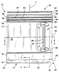
[0010] Fig 1 is a side elevation of a container.
[0011] Fig 2 is a rear elevation of the container as seen from the
right
side of Fig 1.
[0012] Fig 3 is a bottom plan view of the container shown in Fig
1.
[0013] Fig 4 is a partial sectional view taken along line 4 ¨4 of Fig I.
[0014] Fig 5 is a sectional view taken along line 5 ¨ 5 of Fig 1.
[0015] Fig 6 is a detail view of the outward extending flange of
the
container shown in Fig 1 with a sectional view of a foil closure and snap cap.
Description of a Preferred Embodiment
[0016] A container 10 is shown in Fig 1 and the other Figs that
has a
generally cylindrical body 12 surrounding a longitudinal axis Y and a closed
bottom 14. A heel portion 16 can surround the closed bottom 14. The closed
bottom 14 can include a seam 15, as shown in Figs 3 and 4, which is the
product
of the extrusion-blow molding process that can be used to produce such a
container 10. The container can be formed by blow-molding an extruded parison
having a mass that is desirably not greater than 135 grams. The heel portion
16
can include a cylindrical upper portion 18 connected to the perimeter of the
body 12. An arcuate lower portion 20 can connect the closed bottom 14 to a
4

CA 02771163 2012-02-14
WO 2011/043956 PCT/US2010/050498
lower edge 22 of the cylindrical upper portion 18. A lug 24 is defined by a
chordal wall 26 parallel to the longitudinal axis Y and an adjoining
horizontal
surface 28. The chordal wall 26 can connect the closed bottom 12 to the
adjoining horizontal surface 28. The horizontal surface 28 can join the
chordal
wall 26 to the cylindrical upper portion 18 of the heel 16 under a back label
surface 30. The back label surface 30 is separated from a front label surface
32
by an opposed pair of longitudinally extending inward protrusions 34 forming a

graspable handle. As best seen in Fig 5, the front label surface 32 can occupy
at
least 180 of the body 12 while the back label surface 30 is generally smaller
than the front label surface 32. Each inward protrusion 34 can include a
plurality
of longitudinal ridges 36 on a forwardly facing surface 38 of the inward
protrusion 34. A preferred location for the longitudinal ridges 36 is
illustrated in
Fig 5.
[0017] The container 10 can also include an open top 40 having an
outwardly extending flange 42. A foil 44 can be sealed to the outwardly
extending flange 42 as shown in Fig 6 to close the open top 40. The foil 44
can
comprise a metal layer 43 and a thermoplastic layer 45. A cap 46 can be
positioned over the foil 44 that can be removably connected to the outwardly
extending flange 42 by a downwardly extending peripheral edge 47. When the
foil is present, the cap 46 acts to protect the foil 44. Once the foil 44 is
removed
from the container 10, cap 46 can be used to close the open top 40 and inhibit

access to the interior volume if the body 12. A plurality of circumferential
ribs 48
can be situated between an upper end 50 of the inward protrusions 34 and the
outwardly extending flange 42 that can assist the container10 to retain its
cylindrical shape while being stored in a standard food inventory storage
rack.
The plurality of circumferential ribs 48 can include a plurality of outermost
surfaces 52 and a set of indentations 54 vertically separating each rib 48
from
any adjacent rib. The outermost surfaces 52 of the ribs 48 can have a diameter

that is the same as the cylindrical upper portion 18 of the heel 16. The set
of
5

CA 02771163 2014-09-30
WO 2011/043956 PCT/US2010/050498
indentations 54 can have an innermost diameter that is the same as the
cylindrical perimeter portion of the body 12. The container 10 can also have a

neck portion 56 separating the plurality of circumferential ribs 48 from the
outwardly extending flange 40. The neck portion 56 can have a diameter less
than the innermost diameter of the set of indentations 54.
[0018] As best seen in Fig 5, the forwardly facing surface 38 of
each
inward protrusion 34 can lie in part in a plane defined by a radius R through
the
longitudinal axis Y. The forwardly facing surface 38 of each inward protrusion
34
can be angularly displaced from a plane S passing vertically through the back
label surface center by an angle a of between 300 and 40 . A rearwardly facing
surface 58 of each inward protrusion 34 can be inclined at an angle f3 of
between
70 and 80 from a plane T passing vertically through the center of the back
label
surface 30 and the center of the front label surface 32. To provide a
convenient
grip for the container 10, the minimum distance D1 separating the innermost
surfaces of the inward protrusions 34 can be between 40% and 45% of the
diameter D of the cylindrical perimeter of the body 12, while the maximum
distance 02 separating rearward edges of the inward protrusions can be between

50% and 55% of the diameter D of the cylindrical perimeter of the body 12.
[0019] While these features have been disclosed in connection with
the
illustrated preferred embodiment, other embodiments of the invention will be
apparent to those skilled in the art as defined in the following claims.
6

Dessin représentatif
Une figure unique qui représente un dessin illustrant l'invention.
États administratifs

Pour une meilleure compréhension de l'état de la demande ou brevet qui figure sur cette page, la rubrique Mise en garde , et les descriptions de Brevet , États administratifs , Taxes périodiques et Historique des paiements devraient être consultées.

États administratifs

Titre Date
Date de délivrance prévu 2015-11-03
(86) Date de dépôt PCT 2010-09-28
(87) Date de publication PCT 2011-04-14
(85) Entrée nationale 2012-02-14
Requête d'examen 2013-01-14
(45) Délivré 2015-11-03

Historique d'abandonnement

Il n'y a pas d'historique d'abandonnement

Taxes périodiques

Dernier paiement au montant de 263,14 $ a été reçu le 2023-08-09


 Montants des taxes pour le maintien en état à venir

Description Date Montant
Prochain paiement si taxe générale 2024-09-30 347,00 $
Prochain paiement si taxe applicable aux petites entités 2024-09-30 125,00 $

Avis : Si le paiement en totalité n'a pas été reçu au plus tard à la date indiquée, une taxe supplémentaire peut être imposée, soit une des taxes suivantes :

  • taxe de rétablissement ;
  • taxe pour paiement en souffrance ; ou
  • taxe additionnelle pour le renversement d'une péremption réputée.

Les taxes sur les brevets sont ajustées au 1er janvier de chaque année. Les montants ci-dessus sont les montants actuels s'ils sont reçus au plus tard le 31 décembre de l'année en cours.
Veuillez vous référer à la page web des taxes sur les brevets de l'OPIC pour voir tous les montants actuels des taxes.

Historique des paiements

Type de taxes Anniversaire Échéance Montant payé Date payée
Le dépôt d'une demande de brevet 400,00 $ 2012-02-14
Taxe de maintien en état - Demande - nouvelle loi 2 2012-09-28 100,00 $ 2012-02-14
Enregistrement de documents 100,00 $ 2012-04-17
Requête d'examen 800,00 $ 2013-01-14
Taxe de maintien en état - Demande - nouvelle loi 3 2013-09-30 100,00 $ 2013-09-06
Taxe de maintien en état - Demande - nouvelle loi 4 2014-09-29 100,00 $ 2014-09-03
Taxe finale 300,00 $ 2015-07-03
Taxe de maintien en état - Demande - nouvelle loi 5 2015-09-28 200,00 $ 2015-08-31
Taxe de maintien en état - brevet - nouvelle loi 6 2016-09-28 200,00 $ 2016-09-08
Taxe de maintien en état - brevet - nouvelle loi 7 2017-09-28 200,00 $ 2017-09-06
Taxe de maintien en état - brevet - nouvelle loi 8 2018-09-28 200,00 $ 2018-09-05
Taxe de maintien en état - brevet - nouvelle loi 9 2019-09-30 200,00 $ 2019-09-04
Taxe de maintien en état - brevet - nouvelle loi 10 2020-09-28 250,00 $ 2020-09-02
Taxe de maintien en état - brevet - nouvelle loi 11 2021-09-28 255,00 $ 2021-09-08
Taxe de maintien en état - brevet - nouvelle loi 12 2022-09-28 254,49 $ 2022-08-10
Taxe de maintien en état - brevet - nouvelle loi 13 2023-09-28 263,14 $ 2023-08-09
Titulaires au dossier

Les titulaires actuels et antérieures au dossier sont affichés en ordre alphabétique.

Titulaires actuels au dossier
AMCOR RIGID PLASTICS USA, INC.
Titulaires antérieures au dossier
S.O.
Les propriétaires antérieurs qui ne figurent pas dans la liste des « Propriétaires au dossier » apparaîtront dans d'autres documents au dossier.
Documents

Pour visionner les fichiers sélectionnés, entrer le code reCAPTCHA :


Pour visualiser une image, cliquer sur un lien dans la colonne description du document. Pour télécharger l'image (les images), cliquer l'une ou plusieurs cases à cocher dans la première colonne et ensuite cliquer sur le bouton "Télécharger sélection en format PDF (archive Zip)" ou le bouton "Télécharger sélection (en un fichier PDF fusionné)".

Liste des documents de brevet publiés et non publiés sur la BDBC .

Si vous avez des difficultés à accéder au contenu, veuillez communiquer avec le Centre de services à la clientèle au 1-866-997-1936, ou envoyer un courriel au Centre de service à la clientèle de l'OPIC.


Description du
Document 
Date
(yyyy-mm-dd) 
Nombre de pages   Taille de l'image (Ko) 
Abrégé 2012-02-14 1 74
Revendications 2012-02-14 5 196
Dessins 2012-02-14 6 84
Description 2012-02-14 6 280
Dessins représentatifs 2012-03-28 1 8
Page couverture 2012-04-24 2 52
Description 2014-09-30 6 291
Revendications 2014-09-30 3 125
Dessins représentatifs 2015-10-16 1 8
Page couverture 2015-10-16 2 52
PCT 2012-02-14 2 91
Cession 2012-02-14 5 109
Cession 2012-04-17 13 627
Poursuite-Amendment 2013-01-14 2 45
Poursuite-Amendment 2013-04-22 1 31
Taxes 2013-09-06 1 33
Poursuite-Amendment 2014-03-31 2 88
Poursuite-Amendment 2014-09-30 11 476
Taxe finale 2015-07-03 1 46