Sélection de la langue

Search

Sommaire du brevet 2776772 

Énoncé de désistement de responsabilité concernant l'information provenant de tiers

Une partie des informations de ce site Web a été fournie par des sources externes. Le gouvernement du Canada n'assume aucune responsabilité concernant la précision, l'actualité ou la fiabilité des informations fournies par les sources externes. Les utilisateurs qui désirent employer cette information devraient consulter directement la source des informations. Le contenu fourni par les sources externes n'est pas assujetti aux exigences sur les langues officielles, la protection des renseignements personnels et l'accessibilité.

Disponibilité de l'Abrégé et des Revendications

L'apparition de différences dans le texte et l'image des Revendications et de l'Abrégé dépend du moment auquel le document est publié. Les textes des Revendications et de l'Abrégé sont affichés :

  • lorsque la demande peut être examinée par le public;
  • lorsque le brevet est émis (délivrance).
(12) Brevet: (11) CA 2776772
(54) Titre français: RAIDISSEUR DE GAINE
(54) Titre anglais: DUCTWORK STIFFENER
Statut: Octroyé
Données bibliographiques
(51) Classification internationale des brevets (CIB):
  • F16L 55/00 (2006.01)
  • F16L 9/04 (2006.01)
  • F24F 13/02 (2006.01)
(72) Inventeurs :
  • MURCHIE, PHILLIP W. (Etats-Unis d'Amérique)
(73) Titulaires :
  • MURCHIE, PHILLIP W. (Etats-Unis d'Amérique)
(71) Demandeurs :
  • MURCHIE, PHILLIP W. (Etats-Unis d'Amérique)
(74) Agent: MOFFAT & CO.
(74) Co-agent:
(45) Délivré: 2014-10-28
(22) Date de dépôt: 2012-05-14
(41) Mise à la disponibilité du public: 2013-03-26
Requête d'examen: 2012-05-14
Licence disponible: S.O.
(25) Langue des documents déposés: Anglais

Traité de coopération en matière de brevets (PCT): Non

(30) Données de priorité de la demande:
Numéro de la demande Pays / territoire Date
13/245,404 Etats-Unis d'Amérique 2011-09-26

Abrégés

Abrégé français

La gaine utilisée dans des systèmes de chauffage et de conditionnement dair est dotée de barres transversales internes fixées aux parois de la gaine pour empêcher la flexion vers lintérieur ou lextérieur en réaction à une pression différentielle qui pourrait autrement faire seffondrer les parois, soit vers lintérieur, soit vers lextérieur, et causer léchec du système. Les barres transversales sont espacées le long de la gaine et les extrémités opposées de chaque barre transversale sont accueillies dans les cavités correspondantes, en plus dy être fixées, qui sont disposées de façon interne sur les parois opposées de la gaine.


Abrégé anglais

The ductwork utilized in heating and air conditioning systems is provided with internal crossbars secured to the sides of the duct to prevent inward or outward flexing in response to a pressure differential that could otherwise cause collapse of the sides, either inward or outward, and failure of system. The crossbars are spaced along the run of the duct with the opposed ends of each crossbar received within and secured to corresponding sockets mounted internally on opposite walls of the duct.

Revendications

Note : Les revendications sont présentées dans la langue officielle dans laquelle elles ont été soumises.


-6-
CLAIMS
Having thus described the invention, what is claimed as new and desiredd to be

secured by Letters Patent is as follows:
1. In an air duct having opposed sides, a stiffener comprising:
a crossbar in the duct having a pair of opposed ends,
a pair of inwardly projecting, opposed receptacles secured to respective
opposite sides of
the duct from the inside of the duct with two or more fasteners extending
through the
duct, said fasteners capable of engaging said duct independently of any
predrilled
holes in the duct, each of said pair of inwardly projecting, opposed
receptacles
having a recess therein receiving a corresponding end of said crossbar to
prevent
displacement thereof, and
a cross-screw extending through a side of each of said receptacles and into
said
corresponding received end securing said received end of said crossbar thereto
to
prevent withdrawal of said crossbar from said receptacles when the air duct is

pressurized to preclude inward or outward flexing of said sides of the duct in

response to a pressure differential.
2. The stiffener as claimed in claim 1, wherein a plurality of said crossbars
and
receptacles are spaced along said duct.
3. The stiffener as claimed in claim 2, wherein said plurality of said pairs
of
crossbars and receptacles are spaced along said length of the duct with the
crossbars disposed at
approximately a right angle to each other, whereby to provide additional
resistance to flexing of
the sides of the duct in response to a pressure differential.
4. The stiffener as claimed in any one of claims 1 to 3, further comprising a
neoprene pad between each of said opposed receptacles and said respective
opposite sides of the
air duct.

Description

Note : Les descriptions sont présentées dans la langue officielle dans laquelle elles ont été soumises.


CA 02776772 2012-05-14
DUCTWORK STIFFENER
FIELD OF THE INVENTION
[0001] This
invention relates to ductwork utilized in heating and air conditioning
systems to convey forced air from a heating or an air conditioning system to
outlets that
supply heated, ambient or refrigerated air to a home, building or other
enclosed structure and,
more particularly, to an improvement in such systems which minimizes the
likelihood of
distortion of the walls of the ductwork in response to a pressure
differential, i.e., outward
distortion and collapse of the walls in response to an increase in internal
pressure, or inward
distortion of the walls in response to a decrease in internal pressure.
BACKGROUND OF THE INVENTION
[0002] Forced air
heating and air conditioning systems employ runs of ductwork
from the heating/cooling source to the rooms or other interior spaces of a
home, commercial
building or other structure. Heated or chilled air is supplied via conduits to
various rooms of
a home, occupied spaces of commercial buildings, schools and hospitals, and
other structures
that may be occupied by people or utilized for industrial or storage purposes.
Typically, runs
of ductwork extend from the heat source to the various outlet ducts and are
temperature
controlled by a thermostat. Failure of these systems may occur from time to
time, however,
and a common cause of such failure in large installations in particular is a
collapse of the
ductwork that carries the heat or air conditioning load. In particular, excess
internal or
external pressure is a common cause of the damage to ductwork resulting in
distortion or
collapse of the walls of the ductwork in response to the pressure imbalance.
In addition to
excess pressure, inadequate support of the ductwork may also cause distortion
or collapse of
the ducts and undesired sound due to pressure differential that may annoy
occupants of the
building.

= CA 02776772 2014-03-19
-2-
SUMMARY OF THE INVENTION
[0003] In an embodiment of the present invention the aforementioned
problem is
addressed by providing, in one aspect of the present invention, a crossbar in
the duct
having a pair of opposed ends received by receptacles secured to opposite
sides of the duct
to prevent flexing of the sides of the duct and ultimate failure in response
to a pressure
differential.
[0004] In another aspect of the invention, pairs of inwardly
projecting, opposed
receptacles are secured to opposite sides of the duct and each have a recess
therein
receiving a corresponding end of a crossbar to thereby prevent flexing of the
sides of the
duct and failure thereof in response to a pressure differential.
[0005] In another aspect of the invention, the crossbars are
employed in pairs
spaced along the length of the duct with the crossbars of each pair disposed
at
approximately a right angle to each other, thus providing additional
resistance to flexing of
the sides of the duct in response to a pressure differential.
[0006] A further aspect of the present invention is the utilization
of opposed
sockets within the ductwork that project thereinto and receive the
corresponding ends of
the installed crossbar, wherein the ends in the sockets are held against
withdrawal by a
cross-screw engaging the socket and the crossbar to secure the received end of
the crossbar
to the socket.
[0007] According to another aspect, the present invention is
directed to, in an air
duct having opposed sides, a stiffener comprising a crossbar in the duct
having a pair of
opposed ends, a pair of inwardly projecting, opposed receptacles secured to
respective
opposite sides of the duct from the inside of the duct with two or more
fasteners extending

= CA 02776772 2014-03-19
-2a-
through the duct, said fasteners capable of engaging said duct independently
of any
predrilled holes in the duct, each of said pair of inwardly projecting,
opposed receptacles
having a recess therein receiving a corresponding end of said crossbar to
prevent
displacement thereof, and a cross-screw extending through a side of each of
said
receptacles and into said corresponding received end securing said received
end of said
crossbar thereto to prevent withdrawal of said crossbar from said receptacles
when the air
duct is pressurized to preclude inward or outward flexing of said sides of the
duct in
response to a pressure differential
10007a]
Other advantages of this invention will become apparent from the following
description taken in connection with the accompanying drawings, wherein is set
forth by
way of illustration and example, an embodiment of the present invention.

CA 02776772 2012-05-14
-3-
BRIEF DESCRIPTION OF THE DRAWINGS
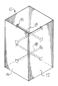
[0008] Fig. I is a perspective view of a short stretch of a heating and
air conditioning
duct showing the addition thereto of the internal components of the present
invention.
[0009] Fig. 2 is a top plan view of the duct of Fig. 1 showing two
crossbars spanning
opposed sides of the rectangular duct and fastened at their ends to the
respective walls
utilizing inwardly projecting, opposed receptacles of the present invention.
[0010] Fig. 3 is a plan view of one of the sockets that receives and holds
the end of a
crossbar.
[0011] Fig. 4 is a side view of one of the sockets on the same scale as
Fig. 3 showing
attachment of the socket to the duct, and a cross-screw that secures the
socket to an end of a
crossbar (shown in broken lines).
[0012] Fig. 5 is a partial section of the socket at a right angle from the
view of Fig. 4.
[0013] Fig. 6 is a perspective view showing one end of a installed
crossbar and
socket.

CA 02776772 2012-05-14
-4-
DETAILED DESCRIPTION
[0014] Referring initially to Figs. 1 and 2, a relatively short segment
of ductwork 10
is shown for illustrative purposes, it being appreciated that in an actual
installation in a home,
building or other structure, the duct will extend a considerable length to
provide heating and
air conditioning to the various rooms or areas of the home or building. The
particular duct 10
illustrated is square in cross section but may be of other geometric shapes as
dictated by
design. The diameter of crossbars is selected depending on the size of the
duct and the
pressure applied.
[0015] Opposed sides 12 and 14 of the duct 10 present a square cross-
sectional
configuration in the illustrated example. A first pair of inwardly projecting,
opposed
receptacles 15 present aligned sockets 16 that receive and secure the
respective ends of a
crossbar 18 as best shown in Figs. 4 and 6 where one of the opposed ends of
the crossbar 18
is shown inserted into socket 16 and held by cross screw 20. Successive pairs
of opposed
sockets 16 secure pairs of crossbars 18 to opposed walls of the duct 10 as
illustrated in Fig. 1
where two spaced pairs of crossbars 18 are illustrated. Although each of the
sockets 16
shown presents a circular opening for receiving the end of a crossbar, other
opening
configurations (square for example) would be employed as required to mate with
the end of
the supported crossbar. In a complete duct system the spaced pairs of
crossbars 18 would be
installed along the entire length of the ductwork from the heating/air
conditioning source to
the duct outlets.
[0016] Figs. 4, 5 and 6 further show the manner of attachment of each of
the
crossbars 18 to the associated sockets 16. Each socket 16 projects from a
mounting plate 22
(which may be square as illustrated) secured to the associated side or wall 12
or 14 of the

CA 02776772 2012-05-14
4
-5-
duct 10 by two or more spaced sheet metal screws 24 or other suitable
attachment means.
Preferably, a precut neoprene pad 25 underlies each of the plates 22 to assure
proper seating.
Each screw 24 may be inserted from within the duct (Fig. 4) or, more
typically, from outside
the duct 10 as illustrated in Figs. 5 and 6 which shows one screw 24a
projecting into the duct.
As illustrated, each of the sockets 16 has four recesses 26 presenting
quadrants, each of
which has a central opening 27 for receiving the cross-screw 20 that extends
into the socket
and into an opening 30 in the associated crossbar to fasten it to the socket.
Typically, two
screws 24 inserted at diagonally opposite corners of each plate 22 adequately
secure each
socket 16 to the wall of the air duct 10, but four screws 24 (not illustrated)
may be used if
desired. To assure proper alignment, a centering notch 32 (Figs. 3 and 8) is
provided in each
edge of each plate 22.
[0017] It should be understood while certain forms of this invention have
been
illustrated and described, it is not limited thereto except insofar as such
limitations are
included in the following claims.

Dessin représentatif
Une figure unique qui représente un dessin illustrant l'invention.
États administratifs

Pour une meilleure compréhension de l'état de la demande ou brevet qui figure sur cette page, la rubrique Mise en garde , et les descriptions de Brevet , États administratifs , Taxes périodiques et Historique des paiements devraient être consultées.

États administratifs

Titre Date
Date de délivrance prévu 2014-10-28
(22) Dépôt 2012-05-14
Requête d'examen 2012-05-14
(41) Mise à la disponibilité du public 2013-03-26
(45) Délivré 2014-10-28

Historique d'abandonnement

Il n'y a pas d'historique d'abandonnement

Taxes périodiques

Dernier paiement au montant de 125,00 $ a été reçu le 2024-05-10


 Montants des taxes pour le maintien en état à venir

Description Date Montant
Prochain paiement si taxe générale 2025-05-14 347,00 $
Prochain paiement si taxe applicable aux petites entités 2025-05-14 125,00 $

Avis : Si le paiement en totalité n'a pas été reçu au plus tard à la date indiquée, une taxe supplémentaire peut être imposée, soit une des taxes suivantes :

  • taxe de rétablissement ;
  • taxe pour paiement en souffrance ; ou
  • taxe additionnelle pour le renversement d'une péremption réputée.

Les taxes sur les brevets sont ajustées au 1er janvier de chaque année. Les montants ci-dessus sont les montants actuels s'ils sont reçus au plus tard le 31 décembre de l'année en cours.
Veuillez vous référer à la page web des taxes sur les brevets de l'OPIC pour voir tous les montants actuels des taxes.

Historique des paiements

Type de taxes Anniversaire Échéance Montant payé Date payée
Requête d'examen 400,00 $ 2012-05-14
Le dépôt d'une demande de brevet 200,00 $ 2012-05-14
Taxe de maintien en état - Demande - nouvelle loi 2 2014-05-14 50,00 $ 2014-05-13
Taxe finale 150,00 $ 2014-08-15
Taxe de maintien en état - brevet - nouvelle loi 3 2015-05-14 50,00 $ 2015-05-13
Taxe de maintien en état - brevet - nouvelle loi 4 2016-05-16 50,00 $ 2016-05-12
Taxe de maintien en état - brevet - nouvelle loi 5 2017-05-15 100,00 $ 2017-05-12
Taxe de maintien en état - brevet - nouvelle loi 6 2018-05-14 100,00 $ 2018-03-14
Taxe de maintien en état - brevet - nouvelle loi 7 2019-05-14 100,00 $ 2019-03-14
Taxe de maintien en état - brevet - nouvelle loi 8 2020-05-14 100,00 $ 2020-03-04
Taxe de maintien en état - brevet - nouvelle loi 9 2021-05-14 100,00 $ 2021-04-12
Taxe de maintien en état - brevet - nouvelle loi 10 2022-05-16 125,00 $ 2022-04-20
Taxe de maintien en état - brevet - nouvelle loi 11 2023-05-15 125,00 $ 2023-03-13
Taxe de maintien en état - brevet - nouvelle loi 12 2024-05-14 125,00 $ 2024-05-10
Titulaires au dossier

Les titulaires actuels et antérieures au dossier sont affichés en ordre alphabétique.

Titulaires actuels au dossier
MURCHIE, PHILLIP W.
Titulaires antérieures au dossier
S.O.
Les propriétaires antérieurs qui ne figurent pas dans la liste des « Propriétaires au dossier » apparaîtront dans d'autres documents au dossier.
Documents

Pour visionner les fichiers sélectionnés, entrer le code reCAPTCHA :


Pour visualiser une image, cliquer sur un lien dans la colonne description du document. Pour télécharger l'image (les images), cliquer l'une ou plusieurs cases à cocher dans la première colonne et ensuite cliquer sur le bouton "Télécharger sélection en format PDF (archive Zip)" ou le bouton "Télécharger sélection (en un fichier PDF fusionné)".

Liste des documents de brevet publiés et non publiés sur la BDBC .

Si vous avez des difficultés à accéder au contenu, veuillez communiquer avec le Centre de services à la clientèle au 1-866-997-1936, ou envoyer un courriel au Centre de service à la clientèle de l'OPIC.


Description du
Document 
Date
(yyyy-mm-dd) 
Nombre de pages   Taille de l'image (Ko) 
Paiement de taxe périodique 2020-03-04 1 66
Paiement de taxe périodique 2021-04-12 1 33
Paiement de taxe périodique 2022-04-20 1 33
Paiement de taxe périodique 2023-03-13 1 33
Abrégé 2012-05-14 1 12
Description 2012-05-14 5 155
Revendications 2012-05-14 2 37
Dessins 2012-05-14 2 52
Dessins représentatifs 2013-02-07 1 10
Page couverture 2013-03-18 1 36
Revendications 2014-03-19 1 41
Description 2014-03-19 6 186
Page couverture 2014-10-01 1 37
Paiement de taxe périodique 2017-05-12 1 60
Paiement de taxe périodique 2018-03-14 1 59
Paiement de taxe périodique 2019-03-14 1 57
Cession 2012-05-14 2 76
Poursuite-Amendment 2013-09-19 2 93
Poursuite-Amendment 2014-03-19 9 371
Taxes 2014-05-13 1 53
Correspondance 2014-08-15 1 40
Paiement de taxe périodique 2024-05-10 1 33
Taxes 2015-05-13 1 59
Paiement de taxe périodique 2016-05-12 1 54