Note : Les descriptions sont présentées dans la langue officielle dans laquelle elles ont été soumises.
CA 02777667 2012-04-13
Lateral wall for a roller press
The invention relates to a lateral wall arrangement for
laterally bounding the roller gap of a roller press
having rolls supported in a machine frame, driven in
opposite directions and forming a roller gap,
comprising a lateral wall, an assembly device and a
suspension for the lateral wall, wherein the lateral
wall is supported in a spring-loaded manner by the
suspension.
In roller presses for the high-pressure comminution of
material to be ground, the material to be comminuted is
discharged uniformly onto the roller gap of two rolls
rotating in opposite directions, the material to be
ground being drawn into the roller gap by the rolls and
compacted there. If the compaction is very high, the
material structure of the material to be comminuted
fractures and forms briquette-like flakes, which leave
the roller gap on the side opposite the feed side.
These flakes can then be de-agglomerated with the
comparatively low expenditure of energy, by which means
a comminuted material to be ground can be obtained. As
mentioned at the beginning, it is important for the
high-pressure comminution to charge the roller gap
uniformly with material to be ground, in order that the
roller press does not operate as a breaker and
therefore exhibit a lower comminution performance. In
order to charge the roller gap uniformly with material
to be ground, the material is distributed uniformly
over the length of the roller gap by a discharge
device. It is necessary to devise a boundary in each
case at the ends of the rolls in order that the
material to be ground does not fall out of the roller
press at these points and this thus leads to a non-
uniform discharge of material over the length of the
roller gap. Such a boundary can in the simplest case
= = CA 02777667 2012-04-13
- 2 -
be a lateral wall in each case, which each bear closely
on the rotating ends of the rolls in the roller press.
However, if one or both rolls of the roller press is
movable as a loose roll, in order to be able to carry
out deflection movements in the event of a non-uniform
discharge of material to be ground, the lateral walls
must be able to follow this mobility. Furthermore, the
lateral walls interfere during the regular maintenance
and the cyclic changing of the rolls, which are
stressed highly by wear, since the lateral walls
firstly have to be dismantled and each individual
dismantling step during a roll change leads to an
undesired prolongation of the stoppage time.
German Laid-open Specification DE 3705051 Al discloses
a roller press in which the lateral walls are fixed by
a link to the lateral walls of the material discharge
device located above the latter and are supported
against the ends of the rolls by an outrigger via
compression springs received in clamping screws.
Because of the compression springs, the lateral walls
suspended on the link are capable of following
deflection movements of the rolls. This type of
suspension has proven worthwhile in operation but is
complicated to dismantle during the regular roll
change.
In German Patent DE 102007032177 B3, a lateral wall for
a roller press is disclosed which is received in a
slotted guide. The slotted guide permits the lateral
wall to carry out a movement during the dismantling of
the rolls in which the lateral wall is moved away from
the end of a roll. Between the lateral wall and the
slotted guide, a lever connected to the lateral wall in
the manner of a rotary joint ensures that the lateral
wall is locked in its operating position. However,
this locking prevents the lateral wall from deflecting
- 3 -
during operation, which means that the lateral wall can be damaged and in the
extreme case can be destroyed.
The invention is therefore based on the object of providing a lateral wall
arrangement for a roller press mentioned at the beginning which is both simple
to dismantle and is also capable of following deflection movements of the
rolls.
According to the invention, a link is proposed as a suspension for the lateral
wall in the simplest case, the link being received in an assembly device. In
order to dismantle it, the entire lateral wall arrangement is separated from
the
machine frame of the roller press, in that the assembly device which carries
the entire lateral wall arrangement is detached from the machine frame. Unlike
the aforementioned prior art, the lateral wall arrangement forms a module of a
roller press, this module permitting the spring-loaded suspension of a lateral
wall.
The invention and further features and advantages thereof will be explained in
more detail by using the exemplary embodiments illustrated schematically in
the figures, in which:
fig. 1 shows the lateral wall arrangement according to the invention in
a side view,
fig. 2 shows the lateral wall arrangement according to figure 1 in a
rear
view,
fig. 3 shows the lateral wall arrangement according to figure 1 in a
front view.
CA 2777667 2017-06-16
CA 02777667 2012-04-13
- 4 -
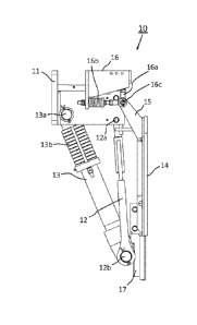
Figure 1 shows a lateral wall arrangement 10 according
to the invention in a side view, in which the three
important constituent parts, namely the assembly device
11, link 12 and lateral wall 14, can be seen clearly.
In the embodiment of the invention illustrated in
concrete terms here, the suspension comprises a three-
joint lever mechanism having two levers coupled to each
other in the manner of a rotary joint via a common
joint 12b, link 12 and spring leg 13 and having
different axes of rotation 12a, 13a, a first lever,
link 12, having an adjustable length and a second lever
comprising a spring leg 13.
In this side view, the lateral wall 14 can be seen only
by way of a narrow profile, the lateral wall 14 being
mounted in the manner of a rotary joint via a lug 15 in
a bearing device 16 with rotary bearing 16c. The
bearing device 16 is in turn fixed to the assembly
device 11 and has two bearing receivers 16a and 16b for
a rotary bearing 16c, via which the rotary bearing 16c
located in the bearing receivers 16a and 16b can move
slightly with two degrees of freedom for the purpose of
fine adjustment. Apart from the
three constituent
parts comprising assembly device 11, link 12 and
lateral wall 14, a compression rod in the form of a
spring leg 13 is also provided, through which the
lateral wall 14 experiences a pressing force of about
20,000 N to the right in this view, the spring leg 13
optionally also having a damping system. The
aforementioned pressing force is generated in spring
leg 13 by a preloaded spring 13b, wherein the spring
13b can comprise a spiral spring or else a disk spring
pack. In operation, the preloaded spring 13b stresses
the spring leg 13, so that the latter experiences a
lengthening force but the preloaded spring 13b is
provided with a stop, so that the spring leg 13 has
reached the maximum length in this view. If a roll
located on the right of the lateral wall 14 in this
CA 02777667 2012-04-13
- 5 -
view and not shown here carries out a deflection
movement and, in the process, swings out slightly to
the left, the lateral wall 14 is forced to the left.
Link 12 follows this movement by means of a rotational
movement of a few degrees oriented in a clockwise
direction. During this rotational movement in a joint
or a rotary bearing about the axis of rotation 12a, the
spring leg 13 is compressed counter to the force of the
preloaded spring 13b with an axis of rotation 13a
offset to the left with respect to axis of rotation
12a, and as a result of this compression, the link 12
experiences a tensile force, for which reason this link
12 can also be designated a tie rod. As a result of
this concerted movement of link 12 and spring leg 13,
the lateral wall 14 deflects to the left, the lateral
wall 14 moving by a short distance in a linear bearing
17 suspended in the manner of a rotary joint, in the
simplest case a dovetail slide. As compared with the
link 12 and the spring leg 13, the lateral wall 14 has
a third axis in rotary bearing 16c, the position of
which is determined by the finely adjusted position of
the bearing receivers 16a and 16b.
When installed in a roller press, the lateral wall
arrangement 10 is fixed to a machine frame of the
roller press via the assembly device 11 at the top left
in figure 1. For the purpose of
dismantling, it is
sufficient for the assembly device 11 to be detached
from the machine frame, it being possible for the
entire lateral wall arrangement 10 to be removed from
the machine frame, not shown here. If appropriate,
before dismantling the lateral wall 10 from a roller
press, it is necessary to displace the bearing device
16, fixed to the assembly device 11 in slots, in the
direction of the machine frame and to lengthen the link
12 by means of a corresponding length adjustment, which
is explained in more detail below. As a result, the
lateral wall 14 is displaced in a parallel manner to
CA 02777667 2012-04-13
- 6 -
the left in figure 1 and removed from a roll not
illustrated in figure 1 but adjoining on the right, and
also from a lateral wall of a discharge device for
material to be ground arranged above the lateral wall
14.
After the lateral wall arrangement 10 has been
reassembled following a roll change, the alignment of
lateral wall 14 can be adjusted finely by adjusting on
the bearing receiver 16a such that the lateral wall 14
has a vertical alignment. In order to adjust
the
lateral wall 14 in its horizontal position, provision
is made to lengthen or to shorten the link 12 by means
of a length adjustment, in the simplest case by
rotating a double nut with left-hand and right-hand
internal thread on a link part in each case having a
left-hand and right-hand external thread, by which
means the position of the connection between link 12
and spring leg 13 by the joint 12b can be changed not
only in the vertical position but also in the
horizontal position. The change in the length of the
link 12 does not change the vertical position of the
lateral wall 14, since it is accommodated in a linear
bearing 17 suspended in the manner of a rotary joint
but, during the change to the length of the link 12,
the horizontal position of the latter is displaced,
since the connection between link 12 and spring leg 13
by means of joint 12b takes the horizontal position of
the lateral wall 14 with it as a result of an
approximately rotational movement in the clockwise
direction. In order to align
the lateral wall 14
finely in the vertical position, provision is made to
adjust the latter by means of an adjustment of the
bearing receiver 16b.
Figure 2 shows the lateral wall arrangement 10
according to figure 1 in a rear view. To be seen
clearly is a flange lla, which is part of the assembly
CA 02777667 2012-04-13
- 7 -
device 11 and via which the entire lateral wall
arrangement 10 is fixed to the machine frame of a
roller press with the aid of the drilled holes lib and
11c.
In this view, it is also possible to see that the link
12 has two limbs 12c and 12d, which enclose the spring
leg 13 symmetrically from two sides. In the
background, it is finally possible to see the lateral
wall 14, which has the shape of a triangle standing on
its point, with two concave sides and a rectilinear
base located at the top.
Figure 3, finally, shows the lateral wall arrangement
according to figure 1 in a front view, which is
dominated by the shape of the lateral wall 14. It can
be seen in this case that, at the lower point, where
the lateral wall 14 comes into contact with the
compaction zone of the roller gap, the lateral wall 14
is equipped with an anti-wear layer 14b, since at this
point the abrasive forces of the material to be ground
which is drawn through the roller gap act most
intensely.
CA 02777667 2012-04-13
- 8 -
LIST OF DESIGNATIONS
Lateral wall 13a Axis of rotation
arrangement 13b Spring
11 Assembly device 14 Lateral wall
ha Flange 14b Anti-wear layer
lib Drilled hole 15 Lug
11c Drilled hole 16 Bearing device
12 Link 16a Bearing receiver
12a Axis of rotation 16b Bearing receiver
12b Joint 16c Rotary bearing
12c Limb 17 Linear bearing
12d Limb
13 Spring leg