Note : Les descriptions sont présentées dans la langue officielle dans laquelle elles ont été soumises.
CA 02784641 2012-06-14
WO 2011/079255 PCT/US2010/061985
ANNULAR BAR GRAPH AND MULTI-SEGMENT DISPLAY
BACKGROUND OF THE INVENTION
Field of the Invention
[0001] The present invention relates to display devices, and more
particularly to illuminated displays that convey information both graphically
and
through text.
Description of Related Art
[0002] Display devices can be formed using multiple light-emitting diodes
(LEDs). For example, bar graphs can be created by arranging LEDs in a line and
selectively activating the LEDs. LEDs can also be used to create letters
and/or
numbers (i.e., alphanumeric information) by appropriately arranging the LEDs
into a
multi-segment display (e.g., a seven-segment display).
BRIEF SUMMARY OF THE INVENTION
[0003] In accordance with one aspect of the present invention, provided is a
display comprising a first plurality of light-emitting elements forming an
annular bar
graph, and a numerical display within the annular bar graph. The annular bar
graph
displays information graphically, and the numerical display simultaneously
displays
the same information numerically.
[0004] In accordance with another aspect of the present invention, provided
is a packaged display device comprising a first plurality of light-emitting
elements
forming an annular bar graph, and a second plurality of light-emitting
elements
forming a multi-segment display within the annular bar graph. The display
device
includes a common housing for the first plurality of light-emitting elements
and the
second plurality of light-emitting elements.
[0005] In accordance with another aspect of the present invention, provided
is a user interface comprising a substrate. An annular touch-sensitive input
is
located on the substrate. A first plurality of light-emitting elements form an
annular
CA 02784641 2012-06-14
WO 2011/079255 PCT/US2010/061985
bar graph. A numerical display is located within both of the annular touch-
sensitive
input and the annular bar graph.
BRIEF DESCRIPTION OF THE DRAWINGS
[0006] FIG. 1 is a plan view of a display device;
[0007] FIG. 2 is a schematic electrical diagram of the display device in FIG.
1;
[0008] FIG. 3 is a partial plan view of a user interface including the display
device of FIG. 1; and
[0009] FIG. 4. is a plan view of a cooktop.
DETAILED DESCRIPTION OF THE INVENTION
[0010] The present invention will now be described with reference to the
drawings, wherein like reference numerals are used to refer to like elements
throughout. In the following description, for purposes of explanation,
numerous
specific details are set forth in order to provide a thorough understanding of
the
present invention. It may be evident, however, that the present invention can
be
practiced without these specific details. Additionally, other embodiments of
the
invention are possible and the invention is capable of being practiced and
carried out
in ways other than as described. The terminology and phraseology used in
describing the invention is employed for the purpose of promoting an
understanding
of the invention and should not be taken as limiting.
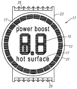
[0011] Figure 1 shows a packaged display device 11 for conveying
information both graphically and alphanumerically. The display device 11
includes
an annular bar graph 13 and a multi-segment display 15 located centrally of
(e.g.,
within) the annular bar graph. The multi-segment display 15 is a numerical
display
(e.g., capable of displaying numbers and optionally letters and/or
characters). In an
embodiment, the multi-segment display 15 can display variable alphanumeric
information. The display device 11 can also include fixed text elements 17
located
centrally of the annular bar graph and adjacent to the multi-segment display,
for
selectively displaying fixed strings of text.
2
CA 02784641 2012-06-14
WO 2011/079255 PCT/US2010/061985
[0012] The annular bar graph 13, multi-segment display 15 and fixed text
elements 17 have light-emitting elements 19 (see FIG. 2) associated therewith
for
creating the displayed information through selective activation of the light-
emitting
elements 19. Example light-emitting elements include LEDs, vacuum fluorescent
displays and liquid crystal displays.
[0013] The light-emitting elements 19 are mounted within a common housing
21 to form the packaged display device 11. The light-emitting elements 19 can
be
mounted within a cylindrical portion of the common housing 21. The common
housing 21 can include a printed circuit board 23, for example, for connecting
the
light-emitting elements to another circuit. The printed circuit board 23 can
include a
plurality of terminals 25 that are capable of being connected to, e.g.,
soldered to, a
substrate such as another printed circuit board. In an embodiment, the display
device is adapted for surface mounting to the substrate. The display device
can be
further adapted for automated assembly to the substrate using known techniques
for
automated assembly of printed circuit boards.
[0014] As shown in FIG. 2, in an embodiment that includes LEDs, the LEDs
can be arranged electrically as a matrix of rows and columns. Selected LEDs
can be
activated by switching the appropriate row and column terminals to form a
completed
electrical circuit. The row and column terminals correspond to respective
terminals
25 on the printed circuit board 23 of the display device 11. In the embodiment
shown in FIG. 2, the display device 11 includes forty-nine (49) LEDs allocated
among seven (7) rows and nine (9) columns. It is to be appreciated that the
display
device can include more or fewer than 49 LEDs, which can be allocated to
various
rows and columns as desired.
[0015] The annular bar graph 13 is formed by a plurality of light-emitting
elements arranged in a circle. Each light-emitting element forms a small
segment of
the annular bar graph 13. In an embodiment, each small segment is an arcuate
segment. In an embodiment, the annular bar graph 13 comprises twenty-five (25)
light-emitting elements. It is to be appreciated that the annular bar graph 13
can
include more or fewer than 25 light-emitting elements.
[0016] Via selective activation of the light-emitting elements, various
display
effects can be created using the annular bar graph 13. For example, a single
light-
3
CA 02784641 2012-06-14
WO 2011/079255 PCT/US2010/061985
emitting element can be activated to provide a small light segment. The small
light
segment can be made to move clockwise or counterclockwise around the annular
bar graph 13 by appropriately activating and deactivating light-emitting
elements in
sequence. The small light segment can be lengthened in a clockwise and/or
counterclockwise direction by activating adjacent light-emitting elements. The
lengthened light segment can be made to move around the annular bar graph 13
and can also be contracted or shortened into a smaller light segment. Further,
multiple light segments can be displayed and made to move around the annular
bar
graph 13 or lengthened/shortened simultaneously.
[0017] As noted above, the multi-segment display 15 can display variable
alphanumeric information. The variable alphanumeric information can be related
to
information displayed graphically by the annular bar graph 13. For example, a
light
segment displayed by the annular bar graph 13 can graphically represent a
level
(e.g., a power level). The same level can simultaneously be displayed as a
number
on the multi-segment display 15. As the light segment moves or is
lengthened/contracted on the annular bar graph 13, the number displayed by the
multi-segment display 15 can change correspondingly.
[0018] The annular bar graph 13 and multi-segment display 15 can also
display different information. For example, the multi-segment display 15 can
display
a level setting set by a user while the annular bar graph 13 displays a
monitored
condition, such as a temperature.
[0019] As noted above, the display device 11 can include fixed text elements
17 for selectively displaying fixed strings of text within the annular bar
graph 13. The
fixed text elements 17 are displayed by activating one or more light-emitting
elements associated with the text elements 17. In FIG. 1, the example text
elements
"power boost" and "hot surface" can be displayed by simultaneously activating
several light-emitting elements that are respectively associated with one of
the text
elements.
For example, each text element 17 can have four (4) associated light-emitting
elements, which are activated simultaneously to display the corresponding text
element.
4
CA 02784641 2012-06-14
WO 2011/079255 PCT/US2010/061985
[0020] The display device 11 can be associated with an input device to form
a user interface. A controller can monitor the input device and display
corresponding
information using the display device 11. The information can be simultaneously
displayed both graphically using the annular bar graph 13 and numerically
using the
multi-segment display 15. An example input device is a potentiometer or rotary
encoder having a control knob. As the control knob is rotated clockwise, for
example, a light segment displayed by the annular bar graph 13 can be
lengthened
while the number displayed on the multi-segment display 15 is increased. As
the
control knob is subsequently rotated counterclockwise, the light segment can
be
contracted or shortened while the displayed number is decreased. It is to be
appreciated that the light segment can be moved circumferentially around the
annular bar graph 13 as the control knob is rotated.
[0021] Turning to FIG. 3, the user input device associated with the display
device can be an annular touch-sensitive input 27. The annular touch-sensitive
input
27 includes a plurality of electrodes 29 mounted to a substrate 31, such as a
printed
circuit board. The electrodes 29 are arranged annularly around the display
device.
Touch sensor circuitry, which may be part of a controller for the user
interface 33,
monitors the electrodes 29 for capacitance changes that are indicative of
touch
events. The controller for the user interface controls operations of the
annular bar
graph 13 and the multi-segment display 15 in accordance with touch events
(e.g.,
rotational inputs) received through the annular touch-sensitive input 27. An
example
controller incorporating touch sensor circuitry for use in a user interface is
model
CY8C24894 from Cypress Semiconductor Corp.
[0022] The substrate 31 can include a through-hole 47 or aperture for the
display device located centrally of the annular touch-sensitive input 27. The
annular
touch-sensitive input 27 surrounds the through-hole 47 and the display device.
The
display device is aligned with the through-hole 47 and mounted to the
substrate 31.
The annular bar graph 13 is located concentrically within the annular touch-
sensitive
input 27. The annular touch-sensitive input 27 has an inner circumference at
generally the same location as the circumference of the through-hole 47, and
the
annular bar graph 13 is located entirely within the inner circumference of the
annular
touch-sensitive input 27. In other embodiments, the annular bar graph 13 can
be
located outside of the inner circumference of the annular touch-sensitive
input 27.
CA 02784641 2012-06-14
WO 2011/079255 PCT/US2010/061985
For example, the annular bar graph 13 can be located behind the annular touch-
sensitive input 27, i.e., between the inner circumference and an outer
circumference
of the annular touch-sensitive input 27, or completely outside of the annular
touch-
sensitive input 27.
[0023] In an embodiment, the display device has a generally flat, circular
upper surface that is mounted flush with an upper surface 35 of the substrate
31
through the through-hole 47, to form a generally smooth, continuous surface of
the
user interface 33. The terminals 25 of the display device 11 (see FIG. 1) can
be
soldered to the lower surface (not shown) of the substrate 31 to secure the
display
device to the substrate.
[0024] The substrate 31 and display device 11 assembly can in turn be
mounted to a touch surface substrate that a user touches to activate the
annular
touch-sensitive input 27. Example touch surface substrates include glass and
plastic
panels. The touch surface substrate can be part of a control panel for a
domestic
appliance and the user interface 33 can control operations of the appliance.
As
shown in FIG. 4, the domestic appliance can be a cooktop 37 having a plurality
of
heating elements 39 (e.g., electrical resistance or induction heating
elements), and
the user interface can control operations of the heating elements according to
user
touches on the cooktop. In FIG. 4, the cooktop 37 is the touch surface
substrate and
the user interface is attached (e.g., fastened or adhered) to the underside of
the
cooktop 37. For example, the substrate 31 can be glued to the underside of the
cooktop. The substrate 31 can have a plurality (e.g., 2, 3, 4 or more) of
annular
touch-sensitive inputs 27 and display devices mounted to the substrate. The
cooktop 37 has a touch control area 49 in register with the user interface 33,
which is
mounted directly beneath the touch control area 49. The touch control area 49
includes graphics 51 to inform the user of the location of the annular touch-
sensitive
inputs.
[0025] The touch surface substrate (e.g., the cooktop 37) can be translucent
or light-diffusing so that the annular bar graph, multi-segment display and
fixed text
elements are not visible when their corresponding light-emitting elements are
deactivated.
6
CA 02784641 2012-06-14
WO 2011/079255 PCT/US2010/061985
[0026] User operation of the annular touch-sensitive input 27 and
corresponding operations of the display device 11 are described below in the
context
of setting a power level for a heating element 39 in a cooktop 37. It is to be
appreciated that the disclosed user interface 33 can be applied to other
appliances
(e.g., dishwashers, washing machines, clothes dryers, refrigerators, freezers,
stoves,
microwave ovens, etc.) and devices requiring a level or magnitude setting from
a
user.
[0027] Referring to FIG. 3, a user can slide a finger 41 in a circular motion
43 clockwise or counterclockwise along the annular touch-sensitive input 27.
Sliding
the finger 41 in a first direction, e.g., clockwise, increases the power level
setting for
the corresponding heating element. Sliding the finger 41 in a second
direction, e.g.,
counterclockwise, decreases the power level setting for the corresponding
heating
element.
[0028] The magnitude of the power level setting is displayed to the user by
the annular bar graph 13 and the multi-segment display 15. As the user slides
the
finger 41 to increase the power level, a rotational light display is generated
by the
annular bar graph 13. For example, a light segment 45 displayed by the annular
bar
graph can be made to lengthen as the power level is increased, or a small
light
segment can be made to move with the finger 41 as power level is increased. As
the
power level is decreased, the light segment 45 can be made to contract or a
small
light segment can be made to move with the finger 41.
[0029] It is to be appreciated that the annular bar graph 13 imitates an
analog gauge and graphically displays information to the user in an analog-
type
format. While the annular bar graph 13 displays the power level information
graphically, the multi-segment display 15 displays the power level information
numerically or alphanumerically. For example, the multi-segment display 15 can
display a decimal number to indicate the power level (e.g. "7.3"), or text
such as "HI"
or "LO" to indicate the power level. The display device 11, therefore, can
display
information both graphically and through text.
[0030] An example power-setting operation can include sliding the finger 41
from a 6:00 position on the annular touch-sensitive input 27 to a 12:00
position, to
establish a "medium" power level setting. As the finger 41 is moved to the
12:00
7
CA 02784641 2012-06-14
WO 2011/079255 PCT/US2010/061985
position, a light segment can lengthen into a semicircle or move with the
finger, and
the multi-segment display 15 can display appropriate text (e.g., "5.0").
Subsequently, the finger can be slid from 12:00 position to the 9:00 position
to
reduce the power level setting. As the finger 41 is moved to the 9:00
position, the
light segment can shorten into a quarter circle or move with the finger, and
the multi-
segment display 15 can display appropriate text (e.g., "2.5").
[0031] Rather than sliding the finger 41 along the annular touch-sensitive
input 27 to increase or decrease a setting, a user can directly touch portions
of the
annular touch-sensitive input to change the setting. For example, the finger
41 can
be slid from the 6:00 position to the 12:00 position to establish an initial
setting.
Subsequently, the 3:00 position can be directly touched once, twice etc., to
increase
the setting to that position, rather than sliding the finger 41 from the 12:00
position to
the 3:00 position.
[0032] It is to be appreciated that the annular bar graph 13 and the multi-
segment display 15 can be provided as separate components, rather than housed
in
the common housing 21.
[0033] It should be evident that this disclosure is by way of example and that
various changes may be made by adding, modifying or eliminating details
without
departing from the fair scope of the teaching contained in this disclosure.
The
invention is therefore not limited to particular details of this disclosure
except to the
extent that the following claims are necessarily so limited.
8