Note : Les descriptions sont présentées dans la langue officielle dans laquelle elles ont été soumises.
CA 02787457 2012-07-18
WO 2011/120787 PCT/EP2011/053787
1
Description
CUTTERBAR SUPPORT FOR A CROP HARVESTING HEADER
Technical Field
[0001] The present invention relates generally to crop harvesting headers for
use
with crop harvesting devices. It relates more particularly to a system for
supporting a cutterbar of a crop harvesting header.
Background Art
[0002] The cutting assemblies of the known large headers of plant-cutting
machines (e.g., combine, windrower) are typically driven by an oscillating
drive, which can include, but is not limited to, an eccentric shaft on a
rotating hub, a wobble drive, or a similar well-known
commercially-available device. A cutting assembly is typically supported
by a flexible cutterbar that spans the width of the opening of the crop
harvesting header. The cutterbar is typically supported by arms that
extend transverse to the cutterbar. Unfortunately, the weight of cutting
assembly is not uniformly distributed across the cutting width of the
harvesting header, possibly causing bowing of the cutter bar, and the
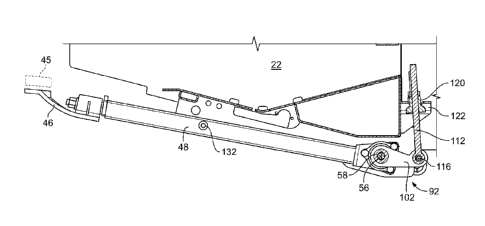
cutting assembly, resulting in uneven cutting height of the plant, as well as
other undesirable results.
[0003] What is needed is a system that provides substantially uniform support
along the length of the cutting assembly by permitting selective adjustment
of the forces the arms provide to the cutter bar.
Disclosure of Invention
[0004] The present invention relates to a system for supporting a cutterbar of
a
crop harvesting header as set forth in claim 1 of the appended claims.
[0005] According to a second aspect of the present invention, there is further
provided a system for supporting a cutterbar of a crop harvesting header
comprising: a first arm pivotably secured to the header, the first arm
including a first portion configured to support the cutterbar, the first arm
including a second portion including a torsion device connected to an
adjustment assembly and configured to be pivotably rotatable about an
axis substantially parallel to the cutterbar to selectably increase or
decrease a force appliable to the first portion in order to raise or lower the
CA 02787457 2012-07-18
WO 2011/120787 PCT/EP2011/053787
2
first portion with respect to the header; the adjustment assembly including
a second arm interconnecting the torsion device and a first adjustment
device having a first segment, the first adjustment device configured to
movably receive a second adjustment device; wherein the first segment of
the first adjustment device is configured to follow a predetermined path in
a first direction with respect to the axis in response to movement of the
second adjustment device in a first tendency with respect to the first
adjustment device; wherein further movement of the second adjustment
device in the first tendency with respect to the first adjustment device
increases an amount of torsional force applied to the first portion of the
first arm with respect to the header, resulting in a decrease of the force
applied to the first portion in order to raise the first portion with respect
to
the header; wherein the first segment of the first adjustment device is
configured to follow a predetermined path in a second direction with
respect to the axis in response to movement of the second adjustment
device in a second tendency opposite the first tendency with respect to the
first adjustment device; and wherein further movement of the second
adjustment device in the second tendency with respect to the first
adjustment device decreases an amount of torsional force applied to the
first portion of the first arm with respect to the header, resulting in an
increase of the force appliable to the first portion and order to raise the
first
portion with respect to the header.
[0006] Additionally the second adjustment device in either aspect of the
invention
may be moved in either of the first tendency or the second tendency
without removing the second adjustment device from the first adjustment
device.
[0007] An advantage of the present invention is the application of a
substantially
uniform support force for the cutterbar, resulting in improved crop
harvesting.
[0008] Other features and advantages of the present invention will be apparent
from the following more detailed description of the preferred embodiment,
taken in conjunction with the accompanying drawings which illustrate, by
way of example, the principles of the invention.
CA 02787457 2012-07-18
WO 2011/120787 PCT/EP2011/053787
3
Brief Description of Drawings
[0009] FIG. 1 is a front view of an embodiment of a crop harvesting device and
harvesting header of the present invention.
[0010] FIG. 2 is a top perspective view of the crop harvesting device of FIG.
1 of
the present invention.
[0011] FIG. 3 is a cross section taken along line 3-3 of the present
invention.
[0012] FIG. 4 is an exploded view of a cutterbar support arm of the present
invention.
[0013] FIG. 5 is a forward-looking end view of an adjustment device of the
present invention.
[0014] FIG. 6 is an enlarged end view of a torsion device of the present
invention.
[0015] FIG. 7 is a cross section taken along line 7-7 from FIG. 6 of the
present
invention.
[0016] FIGS. 8-9 are enlarged top perspective views of the adjustment device
of
FIG. 5 shown in different rotational positions of the present invention.
[0017] FIG. 10 a cross section taken along line 10-10 of the adjustment device
of
FIG. 5 of the present invention.
[0018] FIGS. 11-12 are embodiments of a second adjustment device of the
present invention.
[0019] Wherever possible, the same reference numbers will be used throughout
the drawings to refer to the same or like parts.
Mode(s) for Carrying Out the Invention
[0020] A combine 20, which is a well-known agricultural cutting and harvesting
machine, is shown in FIG. 1. Combine 20 includes a header 22, which is
configured to cut or sever crops, including (without limitation) small grains
e.g., wheat, soybeans), and to induct the cut or severed crops into a
feeder 26. Both functions can be performed as combine 20 moves forward
over a crop field.
[0021] Header 22 is attached to a forward end 24 of combine 20 and includes a
pan or floor 28 that is supported in desired proximity to the surface of a
crop field. Header 22 includes an elongated sidewardly extending sickle 30
along a forward edge portion 32 (see FIG. 2) of floor 28. A cutter or sickle
30 is configured to cut or sever crops, in preparation for induction into a
CA 02787457 2012-07-18
WO 2011/120787 PCT/EP2011/053787
4
feeder 26. Additionally, header 22 may include an elongate, sidewardly
extending reel 34 disposed above sickle 30. Reel 34 is rotatable in a
direction suitable for facilitating the induction of cut or severed crops into
feeder 26. Header 22 further includes an elongate, rotatable auger 36,
which extends in close proximity to a top surface 38 of floor 28 and has
helical flights therearound. Auger 36 is configured to cooperate with reel
34 in conveying cut or severed crops to feeder 26, which is configured to
convey the cut or severed crops into combine 20 for threshing and
cleaning. Alternatively, instead of rotatable auger 36, header 22 may
include a draper header or other crop harvesting/gathering header.
[0022] Sickle 30 extends along a forward edge 40 of floor 28, and generally is
bounded by a first side edge 42 and an opposing second side edge 44,
both of floor 28. Sickle 30 is supported by a cutterbar 45 (see FIG. 3)
which is likewise supported by a first portion 46 of an elongated member
or first arm 48 that will be discussed in further detail below. During
operation, sickle 30 reciprocates rapidly to effect a cutting or severing
action that cuts or severs plant stems, stalks or other material present
between the blades of the sickle. As denoted by arrow 50, the sickle
blades can reciprocate sideways.
[0023] As shown in FIGS. 3-5, a C-bracket or second portion 52 of member or
first arm 48 is pivotably secured to header 22 about an axis 56 by a rod 58
having a non-circular periphery, such as a hexagonal periphery. Rod 58
further extends through openings formed in plates 94, 96 that are secured
to header 22 and laterally surround second portion 52. In other words, rod
58 extends through each of plates 94, 96, apertures 98 formed in second
portion 52 and torsion device 90. That is, fasteners 104 are first inserted
through respective aligned openings 106 in second portion 52 and
apertures formed in torsion device 90 to secure the torsion device to the
second portion (assembling the exploded view of FIG. 4). Once the torsion
device 90 is assembled to the second portion 52, aperture 98 of second
portion 52 is positioned between and aligned with openings (not shown)
formed in plates 94, 96 and their respective bushings 100, rod 58 may
then be inserted through plates 94, 96, bushings 100, second portion 52
CA 02787457 2012-07-18
WO 2011/120787 PCT/EP2011/053787
and torsion device 90 (see FIG. 5). After insertion of rod 58, the outer
periphery of rod 58 and an inside surface 80 (see FIG. 4) of torsion device
90 are placed in a non-rotating relationship, i.e., they become mated
surfaces. Finally, opening 108 (see FIG. 8) of second arm 102 is aligned
and slid over rod 58, with opening 108 and rod 58 defining mating surfaces
and fastener 110 installed in rod 58 to secure rod 58 in its installed
position. Although second arm 102 forms part of adjustment assembly 92,
adjustment assembly 92 will be discussed in further detail below. At this
point, in response to first arm 48 being urged into rotational movement
about axis 56, by virtue of the mating surfaces between rod 58 and inside
surface 80 of torsion device 90 and between opening 108 of second arm
102 and rod 58, rod 58 and second arm 102 would each be urged into
rotation about axis 56.
[0024] Figures 6-7 show a side view and a cross section, respectively, of
torsion
device 90. Torsion device 90 includes a housing 60 includes a plurality of
lobes 64 having corresponding apertures 62 formed in the lobes,
permitting the housing to be secured to other structure, such as plate 94,
96 (FIG. 5) by mechanical fasteners 104 extending through the other
structure and apertures 62. Housing 60 includes an inside surface 66 that
may include a tapered surface, such as shown in Figure 7. A member 68,
which includes an inside surface 70 and an outside surface 72, is
composed of a resilient material and is inserted inside of housing 60. In
one embodiment, member 68 is composed of a non-metal, such as a
rubber material. Inside surface 66 of housing 60 is configured to receive
outside surface 72 of member 68 and define a substantially non-rotational
contact therebetween. Stated another way, subsequent to insertion of
member 68 inside of housing 60, in response to a rotational movement 86
applied in a clockwise direction about axis 56 to housing 60 and an
opposed rotational movement 88 applied in a counter clockwise direction
about axis 56 to member 68, inside surface 66 and outside surface 72
should not rotatably move with respect to each other. Such non-rotational
contact may be established by application of adhesives, interference-fit
(due to the periphery of inside surface 66 being larger than the periphery
CA 02787457 2012-07-18
WO 2011/120787 PCT/EP2011/053787
6
of outside surface 72), mating surface features, such as splines, or the
like.
[0025] As further shown in FIGS. 6-7, inside surface 70 of member 68 is
configured to receive a sleeve 76 having an outside surface 78 and inside
surface 80. Housing 60 and sleeve 76 are composed of substantially rigid
materials, such as metals. When member 68 and sleeve 76 are
assembled together, inside surface 70 of the member and outside surface
78 of the sleeve define a substantially non-rotational contact
therebetween, as discussed above. Inside surface 80 of sleeve 76 defines
a geometric shape that is configured to receive an object, such as a shaft,
in a substantially non-rotational contact. As shown in FIG. 6, inside surface
80 defines a hexagonal profile, although other profiles may be used. In a
further embodiment, sleeve 76 may not be used, if inside surface 70 of
member 68 defines a hexagonal profile, for example.
[0026] As shown in FIG. 7, member 68 includes recessed ends 74. In one
embodiment, recessed ends 74 may be created during the normal cooling
process of member 68, which may be composed of rubber or another
suitable resilient material. That is, member 68 may be heated to a liquid
state and then installed while in the liquid state, such as by pouring or
injection molding, into housing 60 between inside surface 70 and outside
surface 72. During cooling, member 68 bonds to each of inside surface 70
and outside surface 72. In an alternate embodiment, member 68 may be
press-fit between inside surface 70 and outside surface 72. In yet another
embodiment, member 68 may be secured between inside surface 70 and
outside surface 72 by use of an adhesive.
[0027] In summary, by virtue of the collective substantially non-rotational
contacts
established between corresponding surfaces of housing 60, member 68,
sleeve 76 and a shaft received by the sleeve, in response to a rotational
movement 86 about axis 56 applied by a shaft 58, and a counter rotational
movement 88 about axis 56 applied to oppose the rotational movement
applied by the shaft, the member is subjected to a torsional force, which is
the basis for the equalizing torsional force provided by the support system.
[0028] It is to be understood that irrespective the utilization or inclusion
of a
CA 02787457 2012-07-18
WO 2011/120787 PCT/EP2011/053787
7
sleeve as part of the stabilization system of the present invention, resilient
member 68 is considered to have been placed in a substantially
non-rotational contact with the inside surface of the member with that of
the object being inserted inside the sleeve. For example, the sleeve could
be associated with either the frame of the header or the frame of the crop
harvesting device, depending upon the application and or installation of
the stabilization system.
[0029] Referring to FIGS. 3, 5, and 8-10, adjustment assembly 92 is now
discussed. Adjustment assembly 92 includes second arm 102 having an
aperture 114 located distantly from opening 108 that is pivotably
connected, such as by fastener 118 to a first segment 116 of a first
adjustment device 112. In one embodiment, first segment 116 includes an
eyelet (see FIG. 3) formed in first adjustment device 112, with the first
adjustment device being a threaded rod. First adjustment device 112 is
movably connected with a second adjustment device 120. In one
embodiment, the second adjustment device is a threaded nut configured to
mate with the first adjustment device. After assembly, second adjustment
device 120 is placed in abutting contact with the portion of header 22. In
one embodiment, the portion of header 22 is a bracket 122, in which the
abutting contact occurs between a portion of the exterior surface of second
adjustment device 120 and at least a portion of a surface of an aperture
124. In one embodiment, at least a portion of second adjustment device
120 includes a tapered surface 126. In one embodiment, tapered surface
126 is curved. Tapered surface 126 is configured to increase the amount
of surface area of the abutting contact between the surface of aperture
124 of bracket 122, thereby reducing the amount of resistance required to
move second adjustment device 120 with respect to bracket 122. In a
further embodiment, the abutting contact surfaces between tapered
surface 126 and aperture 124 define conformal surfaces. That is, the
abutting contact surfaces substantially conform with each other to
maximize the amount of shared surface area to reduce the amount of
resistance between the contact surfaces in response to a given force
directed perpendicular to the contact surfaces. To urge rotational
CA 02787457 2012-07-18
WO 2011/120787 PCT/EP2011/053787
8
movement of second adjustment device 120 with respect to bracket 122, a
region 128 is provided to receive a tool, such as a wrench, or in another
embodiment, the region defines an opening to receive a lever arm.
[0030] By virtue of adjustment assembly 92, such as shown in the FIG. 3, first
portion 46 of first arm 48 can be selectively raised or lowered. In other
words, in response to a rotational movement in a first rotational direction or
a first tendency of second adjustment device 120, second adjustment
device 120 is placed in abutting contact with bracket 122 such that the
length of first adjustment device 112 between bracket 122 and eyelet 116
is increased, urging second arm 102 to rotate about axis 56. When
sufficient rotation of second arm 102 has occurred, and has applied a
sufficient torsional force to torsion device 90, first portion 46 of first arm
48
is raised with respect to header 22 subject to the header encountering a
stop 132 extending from the first arm. Stop 132 may also be employed to
limit the lowest position of first portion 46 with respect to header 22.
Conversely, in response to a rotational movement in a second rotational
direction or a second tendency of second adjustment device 120, second
adjustment device 120 is placed in abutting contact with bracket 122 such
that the length of first adjustment device 112 between bracket 122 and
eyelet 116 is decreased, urging second arm 102 to rotate about axis 56.
When sufficient rotation of second arm 102 has occurred, and has applied
a sufficient torsional force to torsion device 90, first portion 46 of first
arm
48 is lowered with respect to header 22. Depending upon the application,
multiple first arms 48 may be used to provide support for the cutter bar.
[0031] It is also to be understood that while adjustment assembly 92 may be
used
to selectively raise or lower first portion 46 of first arm 48, the same
techniques and interaction between components previously discussed
may also be used to selectively increase or decrease a force that may be
applied to first portion 46 of first arm 48 in order to raise or lower first
portion with respect to header 22. That is, for example, stop 132 extending
from first arm 46 may be in abutting contact (not shown) with header 22
such that first arm 46 cannot be further lowered with respect to header 22.
For purposes of discussion only, and not intending to be limiting, a force of
CA 02787457 2012-07-18
WO 2011/120787 PCT/EP2011/053787
9
X pounds may be required to raise first portion 46 with respect to header
22. By moving second adjustment device 120 in a first tendency, without
raising/lowering first portion 46 with respect to header 22, a force of Y
pounds (Y<X) may then be required to raise first portion 46 with respect to
header 22. Conversely, by moving second adjustment device 120 in a
second tendency, instead of a first tendency, also without raising/lowering
first portion 46 with respect to header 22, a force of Z pounds (Z>X) may
then be required to raise first portion 46 with respect to header 22. In other
words, for purposes of comparison only, X, Y and Z correspond to
magnitudes of forces each being applied in the same direction with respect
to the header in order to raise or lower the header. In one embodiment, the
magnitude of force required to raise or lower the first portion of each first
arm would be the same.
[0032] By virtue of the arrangement of adjustment assembly 92, due to first
adjustment device 112 being located between second arm 102 and
second adjustment device 120, during operation of the adjustment
assembly, first segment or eyelet 116 of first adjustment device 112 is
configured to follow a predetermined path with respect to axis 56. In the
exemplary embodiment as shown in FIG. 10, a predetermined path of first
segment or eyelet 116 corresponds to the radius defined by axis 56 and
aperture 114 of second arm 102. As a result of this arrangement, over the
operating range of adjustment assembly 92, bending forces that could
otherwise be applied to first adjustment device and cause damage to the
first adjustment device are virtually eliminated. That is, by virtue of the
movable abutting contact between tapered surface 126 and the surface of
aperture 124 of bracket 122 over the operating range of angular
movement of second arm 102 about axis 56, including different positions
as shown in respective FIGS. 8 and 9 and as shown in FIG. 10 by a
centerline representation 130 of first adjustment device 112, first
adjustment device 112 can pivot with virtually no lateral forces associated
with the abutting contact.
[0033] Referring to FIGS. 11 and 12, alternative embodiments of second
adjustment device 220, 320 are shown, in which opposed tapered
CA 02787457 2012-07-18
WO 2011/120787 PCT/EP2011/053787
surfaces are combined into a single component. For second adjustment
device 220, the larger ends of the tapered surfaces face each other, which
would normally require removal of the second adjustment device from the
mating first adjustment device if the rotational direction or tendency were
to be reverse. For second adjustment device 320, the smaller ends of the
tapered surfaces face each other, which should not require removal of the
second adjustment device from the mating first adjustment device if the
rotational direction or tendency were to be reversed. However, the
aperture 124 of bracket 122 would need to be "opened up" to form a slot in
order to receive second adjustment bracket 320. Adjustment regions 128
configured to receive tools could be located as shown or in other locations.