Note : Les descriptions sont présentées dans la langue officielle dans laquelle elles ont été soumises.
CA 02789395 2012-08-09
True translation of PCT/EP2011/051419 as filed on February 01, 2011
SP10085US(PCT)
Anchor system of a concrete wall formwork
The invention relates to an anchor system of a concrete wall formwork
with at least one locking device for an anchor bar of the anchor system,
wherein the locking device has a threaded nut element for threading the
anchor bar through a threaded nut thread of the threaded nut element.
Such anchor systems are used in formwork for steel-reinforced concrete
structures. Concrete formwork elements, or formwork elements for short,
of concrete wall formworks are made up of a formwork facing and
supporting elements, for example, longitudinal girders and tie beams.
The two sides of a wall are each formed from one concrete formwork
element, that is, a half-formwork, which are held together by anchor
bars. The anchor bars are inserted through holes in the formwork facing
and fixed at their ends to the elements supporting the formwork facing in
such a way that the tensile force exerted on the anchor bars during
concrete casting is contained. Normally, the two ends of the anchor bars
have threads onto which threaded nuts are threaded as anchor
fastenings. This determines the effective length of the anchor bar and
therefore the thickness of the concrete wall. At the same time, the
pressure exerted during concrete casting by the liquid concrete on the
formwork facing is redirected via the threaded nuts onto the anchor bars.
The anchor bars are subject to tensile stress during this operation.
Between the formwork facings, spacer elements are included in the
volume of the concrete wall to be cast that can absorb the compressive
forces that occur during concrete casting and mounting of the anchor
bars, it being ensured that these compressive forces do not influence the
wall thickness in an unwanted way, that is, reduce it.
CA 02789395 2012-08-09
2
With the known anchor systems, there are problems with inserting the
anchor bar when the concrete wall formwork is erected, if the anchor
insertion holes of the formwork elements with their formwork facings
facing each other and forming the concrete wall are not sufficiently well-
aligned opposite each other.
Because the anchor bar is always inserted from the outside, as seen from
the rear of a first formwork element, through the already erected
formwork elements, the formwork erector who is positioning the anchor
bar cannot see the anchor insertion hole of the second formwork
element. The latter anchor insertion hole is found relatively easily but,
with poorly aligned anchor insertion holes, the anchor bar extends
obliquely with respect to the formwork facing of the formwork elements,
making it very difficult to locate the thread of a locking device on the rear
of the second formwork element. Moreover, if the anchor bar is oblique in
this way, the locking devices cannot lie flat against the formwork
elements around their entire circumference, which results in the forces
that occur during concrete casting being transmitted to the locking
devices concentrated at one point only, which places a heavy load on the
locking devices.
A solution to this problem is proposed in DE 10 2007 004 226 Al. Here,
too, a concrete wall formwork with a first and a second formwork
element, each having a formwork facing, and with an anchor system with
an anchor bar and locking devices is disclosed, wherein the formwork
elements are disposed opposite each other with the front faces of their
formwork facings. Each anchor bar is inserted through a separate anchor
penetration hole in the formwork elements. Furthermore, annular sealing
elements are provided for sealing the anchor penetration hole in the
formwork facings. Each of the locking devices for the anchor bar of the
anchor system of the concrete wall formwork has a threaded nut element
CA 02789395 2012-08-09
3
for threading the anchor bar through a threaded nut thread of the
threaded nut element, and a cap plate. The cap plate is fastened to a
rear face of one of the formwork elements of the concrete wall formwork.
The cap plate has a spherically designed plate region having an opening
in which the threaded nut element is disposed having radial clearance,
wherein the threaded nut element comprises a groove-like radial
circumferential receptacle in which the edges of the opening in the
spherical plate region are received. One threaded nut element of each
anchor system that is disposed on the side of anchor bar tip, has a
tubular guiding device flush with the threaded nut thread of the threaded
nut element provided on the end located at the concrete formwork side,
which is used to more easily locate the thread opening of the threaded
nut head when threading in the anchor bar. Here, however, the problem
arises that due to the oblique position of the anchor bar, excessive strain
is exerted on the sealing element so that during concrete casting, liquid
concrete can escape through the unsealed sections of the anchor
penetration holes.
The object of the invention is to provide a locking device for an anchor
system and a concrete wall formwork that avoids the disadvantages of
prior art, wherein sealing of the anchor penetration holes, through which
obliquely positioned anchor bars are inserted, is improved.
This object is solved by the devices of the independent claims. The
dependent claims are preferred embodiments of the invention.
An inventive locking device is suitable for fastening an anchor bar of an
anchor system of a concrete wall formwork to a formwork element
having a formwork facing. The locking device has an annular sealing
element for sealing an anchor penetration hole in the formwork facing, a
threaded nut element to thread the anchor bar into a threaded nut
CA 02789395 2012-08-09
4
thread of the threaded nut element, and a cap plate. The cap plate can
be fastened to a rear face of the formwork elements of the concrete wall
formwork and has a spherically designed plate region having an opening
in which the threaded nut element is disposed having radial clearance.
Therein, the threaded nut element has a groove-like radially
circumferential receptacle, which accommodates the edges of the
opening in the spherical plate region. A tubular guidance device flush
with the threaded nut thread of the threaded nut element is provided at
the end of the threaded nut element to be located at the concrete
formwork side. According to the invention, the sealing element has an
inner sealing ring exhibiting rubber elasticity or viscoelasticity and the
free end of the guiding device to be located at the formwork element side
protrudes sealingly into the inner sealing ring.
When an inventive locking device is used, essentially no liquid concrete
can escape through the anchor penetration hole between the anchor bar
and the sealing element. Furthermore, the likelihood of damage to the
sealing ring when inserting the anchor bar into the guiding device is
reduced. Additionally, the asymmetrical pressure load exerted on the
rubber-elastic inner sealing ring if the anchor penetration holes are not
entirely aligned is reduced, because a distribution of the load exerted by
the forces generated by pressure load is made possible because the
guiding device makes sealing contact with the inner sealing ring. The
anchor bar itself does not fit closely against the inner sealing ring.
Advantages are optimally provided when the free end of the guiding
device to be located at the formwork element side is terminated by an
outside edge of the inner sealing ring to be disposed on the formwork
facing side or protrudes beyond the outside edge on the formwork facing
side. This also permits use of a particularly thin inner sealing ring, that
is,
CA 02789395 2012-08-09
of an inner sealing ring of low material thickness, giving the sealing ring
a high overall degree of elasticity.
The sealing element especially preferably has a metal sleeve, wherein the
inner sealing ring is sealingly disposed in the metal sleeve. The metal
sleeve prevents damage to the inner sealing ring and protects the inner
sealing ring in anchor penetration holes.
The metal sleeve very advantageously has a radial circumferential
widening on the formwork facing side extending toward the outside,
wherein an end stop for the defined positioning of the sealing element is
constituted in an anchor penetration hole.
The sealing element can have an outer ring preferably made of rigid
plastic, wherein the outer ring is plugged or threaded onto the metal
sleeve. This also permits sealing of the rear face of the formwork facing
into the anchor penetration hole of which the sealing element is inserted.
Moreover, the outer sealing ring can also be used for thread tightening
on the rear.
The free end of the guiding device located at the formwork element side
can especially preferably rest against a radial circumferential and
widened sealing lip of the inner sealing ring. In this case, the free end of
the guiding device can serve as an end stop for an anchor bar to be
threaded in.
Particularly large deflections of the threaded nut element are made
possible when the spherically designed plate region forms a spherical cup
region with a sphere point on the formwork element side, wherein
surface regions of the circumferential receptacle of the threaded nut
element, which rest on the spherically designed plate region, are
CA 02789395 2012-08-09
6
constituted such that they are complementarily shaped with respect to
the spherically designed plate region.
An anti-rotation lock is preferably provided on the threaded nut element.
This anti-rotation lock can, for example, be achieved by constituting the
surfaces of the threaded nut element lying one upon ,the other and the
cap plate with great anti-rotation friction, for example, by means of a
studded surface. If such a locking device is used, the anchor bar, which,
for example, can be threaded from the rear of the first formwork element
into the locking device, which is fastened on the rear of the second
formwork element, can be threaded in without a formwork erector on the
rear of the second formwork element having to operate the locking
device during threading to prevent the threaded nut element from
rotating with the anchor bar. Such a locking device is therefore suitable,
for example, for use in inaccessible regions of the concrete formwork.
The anti-rotation lock preferably has a stop element, wherein the stop
element prevents rotation of the threaded nut element by stopping on a
stop preferably constituted by the fastening elements. This ensures
especially simple and reliable securement against rotation. If the stop
element is constituted as a wing, a stop located further away from the
threaded nut element can also prevent rotation. A stop element is
described, for example, in DE 10 2007 004 226 B3.
A further inventive embodiment of the locking devices for fastening to
the formwork element to be erected first could be to attach the locking
device permanently to the formwork elements. This would have the
advantage of obviating pre-assembly on the formwork element to be
erected first.
An inventive concrete wall formwork has a first and a second formwork
element each of which have a formwork element with a formwork facing
CA 02789395 2012-08-09
7
and an anchor system with an anchor bar and an inventive locking
device, wherein the formwork elements are disposed opposite each other
with the front faces of their formwork facings. The locking device is
disposed on the rear face in the region of an anchor penetration hole in
the formwork facing of the second formwork element, preferably using
fastening means, and the sealing element of the locking device is used to
seal the anchor penetration hole in the formwork facing of the second
formwork element. In this way, the anchor bar is inserted from the rear
face of the formwork facing of the first formwork element through an
anchor penetration hole in the formwork facing of the first formwork
element and through the sealing element and can be or is threaded into
the threaded nut thread of the threaded nut element of the inventive
locking device. Here, the free end of the guiding device is constituted on
the formwork element side and sealingly inserted with the inner sealing
ring into the sealing element so that the free end of the guiding device is
positioned in a way defined by the sealing element on the formwork
facing.
The anchor bar preferably has a rounded anchor bar tip, which makes it
easier to find the thread opening on the free end of the guiding device.
The anchor bar advantageously has a first thread in the end region of the
anchor bar facing away from the anchor bar tip and a second thread in
the end region of the anchor bar near to the anchor bar tip. In the
intermediate region, the anchor bar advantageously has a smooth
surface, which makes it more difficult for the concrete to become
attached.
The anchor rod very advantageously conically tapers between the first
and the second thread, which facilitates removal of the anchor bar after a
cast concrete wall has set. The thread shape of the first thread can differ
from the thread shape of the second thread so that the thread near to
CA 02789395 2012-08-09
8
the anchor point can be constituted very coarsely, which makes it easier
to locate the threaded nut thread of the threaded nut element. The
inventive anchor bar has a stop in the region of the point, which, when
threaded into the guiding device, fits closely in the free end of the
guiding device. Prescribed wall thicknesses are easier to set and
imprecise thicknesses of the wall that is to be cast in concrete are
avoided.
The free end of the guiding device of the locking device located at the
formwork element side is very advantageously aligned with the outside
edge of the inner sealing ring located at the formwork element side or
projects beyond the outside edge on the formwork element side. In this
case, the outside edge of the inner sealing ring of the sealing element
located at the formwork element side is essentially aligned with the front
side of the formwork facing of the second formwork element. In this way,
the edges of the anchor penetration hole are protected and any
asymmetrical forces that are exerted on the inner sealing ring are
optimally distributed across the width of the inner sealing ring. Here, only
the guiding device fits closely in the inner sealing ring.
A further sealing element is especially preferably provided that is
identical to the sealing element of the locking device, in particular, a
sealing element with an identical inner diameter for sealing the anchor
penetration hole in the formwork facing of the first formwork element. In
this case, the anchor bar is inserted through the further sealing element.
The shape of a conically tapering anchor bar is designed such that the
largest diameter of the conical region is adapted to the sealing element
to such that it can be inserted into the further sealing element to
constitute a seal.
CA 02789395 2012-08-09
9
The inventive embodiment of the anchor system has the additional
advantage that the same sealing elements can be used on both sides of
the formwork elements. This is because the anchor bar on one side and
the guiding element on the other side have almost the same outside
diameter in the region of the sealing element.
The invention is explained in more detail below based on an embodiment
and referring to the drawings.
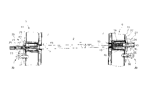
Figure 1 shows an inventive concrete wall formwork in
cross-section in the region where anchor holes are
disposed opposite each other and not aligned.
Figures 2a and 2b each show an inventive concrete wall formwork in
various cross-sections as a detail of Figure 1,
fixed in a position on the rear side of a concrete
formwork element, wherein Figure 2b shows an
enlarged detail of Figure 2a.
Figure 3 shows an enlarged detail of the locking device
shown on the left in Figure 1.
The figures of the drawings show the inventive object highly
schematically and are not scale drawings. The individual parts of the
inventive object are shown in such a way that their structure is clearly
visible.
Figures 2a, 2b and 3 each show detail views of the inventive concrete
wall formwork shown in Figure 1, wherein each figure shows a cross-
section at the level of the longitudinal axis of an anchor bar of the
inventive anchor system, which connects a first and a second formwork
CA 02789395 2012-08-09
element 5,6 of the concrete wall formwork. The formwork elements 5,6
each have a formwork facing 7 and longitudinal beams. Any tie beams
that may exist are not shown due to the detail selected. The formwork
facing 7 is usually mounted on longitudinal beams and tie beams, in
particular, riveted on. The anchor bar 2 is aligned obliquely at an angle a
with respect to the surfaces of the formwork facings 7.
In each case, the sectional representation in Fig. 1 extends through a
longitudinal beam so that each longitudinal beam is only represented by
the wall 11 of the steel section from which the beam is made. The front
sides of the formwork facings 7 of the formwork elements 5,6 are
disposed opposite each other to form a wall to be cast in concrete. One
anchor penetration hole 13 is provided in the region of each longitudinal
beam in the formwork facings 7. The anchor bar 2 is inserted from the
rear of the first formwork element 5 through the anchor penetration
holes 13 and the longitudinal beam, in whose region the anchor
penetration holes 13 are disposed. Annular sealing elements 15 are
disposed and/or inserted in the anchor penetration holes 13 that extend
around the anchor bar 2 in such a way that during concrete casting
essentially no liquid concrete can exit through the anchor penetration
holes 13. On the rear of each of the formwork elements 5,6, one locking
device 20,21 is positioned in the anchor penetration holes 13. The locking
devices 20,21 each have a threaded nut element 23,24 with a threaded
nut thread, that is, a hole with an internal thread, through which the
anchor bar 2 is threaded. The locking devices 20,21 also each have a cap
plate 26,27 with fastening elements 30 for fastening the cap plate 26,27
and therefore the locking device 20,21 on the rear of each one of the
formwork elements 5,6. The fastening elements 30 are constituted by a
hole in the edge region of the cap plate 26,27, through which a threaded
bolt 32 can be or is threaded into a threaded hole 34 on each longitudinal
beam. Clamps, bayonet connectors, and similar fixtures are also
CA 02789395 2012-08-09
11
conceivable as technically equivalent fastening elements 30. The cap
plate 26,27 is made of a steel plate. It has a spherically designed plate
region, that is, a plate region constituted as a spherical cup region, in
which an opening is provided. Each spherical cup region constitutes a
sphere center on the side of the formwork element. That is, the curvature
of the spherical cup region is oriented in such a way that the center is
located in the region of the formwork element 5,6 to which the
associated locking device 20,21 is fastened. This center is preferably
located in the formwork facing plane.
The concave surface of the cap plate 26,27 is disposed with radial
clearance around its entire circumference toward the formwork facing 7
of each formwork element 5,6. The threaded nut element 23,24 of each
locking device 20,21 is positioned in the opening. A radial groove around
the entire circumference is provided on each threaded nut element 23,24
that constitutes a holder 40 in which the edges of the opening in the
spherical plate region of the associated cap plate 26,27 are held. The
holder 40 has a shape corresponding to the spherical plate region so
that, within the radial clearance, deflection of the threaded nut element
23,24 is possible around the entire circumference on the cap plate 26,27,
guided by the cap plate 26,27. The groove can, for example, be
constituted by plugging or threading a ring 41 (Fig. 2a) constituting the
groove wall on the concrete formwork side onto a tubular region of a part
of the threaded nut element 23,24 formed as a domed cap nut.
A tubular guidance device 45 flush with the threaded nut thread of
threaded nut element 24 is provided on the inventive locking device 21
positioned on the second formwork element 6, at the end of the threaded
nut element 24 located at the concrete formwork side. This is, for
example, a sleeve-like extension, which is constituted on the threaded
nut element 24. The thread of the threaded nut element 24 can extend
CA 02789395 2012-08-09
12
fully or partially inside the extension. In this case, the threaded nut
element 24 is constituted as two pieces. It is comprised of the sleeve-like
extension, which is constituted integrally together with the guiding device
45 and in which the threaded nut thread is located, and an anti-rotation
lock 60 that is threaded or plugged thereon and secured with a splint.
The anti-rotation 60 has wing elements that stand radially away from the
threaded nut element, so that even a stop that is located further away
from the threaded nut element 24 can prevent the threaded nut element
24 from turning with the anchor bar 2 when the latter is threaded in.
As can be seen clearly, in particular, in the detail of Figure 2b, the sealing
elements 15 have a rubber-elastic inner sealing ring 46 with a widened
sealing lip 46' and a metal sleeve 47, wherein the inner sealing ring 46 is
sealingly disposed in the metal sleeve 47. The free end of the guiding
device 45 located at the formwork element side is sealingly inserted with
the inner sealing ring 46 into the sealing element 15, which is disposed in
the anchor penetration hole 13 of formwork facing 7 to which the
inventive locking device 21 is fastened. The metal sleeve 47 is provided
with a widened section 49, which is disposed radially on the formwork
facing side and extends outward and which as a positioning aid defines
the slot-in depth of the sealing elements 15 into the anchor penetration
holes 13 and forms edge protection. The guiding device 45 is inserted so
far into the associated sealing element 15 that it extends slightly beyond
the outside surface of the formwork facing 7 and beyond an outside edge
of the inner sealing ring 46 that widens in a bulging manner and is
disposed on the formwork facing side. The protruding, projecting region
is constituted as a free end 51 of the guiding device 45. Likewise, the
free end 51 of the guiding device 45 and the widening 49 of the metal
sleeve 47 slightly project beyond the outside surface of the formwork
facing 7. The sealing elements 15 have an outside ring 48 made of rigid
plastic, which is threaded onto the metal sleeve 47 from the rear of the
CA 02789395 2012-08-09
13
formwork facing 7, wherein, in addition to additional rear sealing of the
anchor penetration hole 13, the sealing elements 15 are fixed in position.
The anchor bar 2, which is inserted through the sealing element by
means of its tip 50, is inserted directly into the guiding device 45, which
is fastened to the anti-rotation lock 60. The anti-rotation lock 60 is
constituted as a cap nut. The pivot point (circle center), around which the
cap nut 45 (guiding device 45, anti-rotation lock 60) can be swiveled,
deflected, or displaced when an anchor bar 2 is inserted, is therefore
located in the region of the plane of the formwork facing 7.
Furthermore, one anti-rotation lock 60 is provided on each of the
threaded nut elements 24 of the locking devices 21, which are on the
rear of the second formwork elements 6, that is, those formwork
elements 6, through which the anchor bars 2 are inserted from the front,
i.e., from the formwork facing 7. These anti-rotation locks 60 are
constituted such that an outer region of the threaded nut elements 24,
during rotation of each threaded nut element 24, can hit a stop
constituted, for example, by the fastening elements 30 of the associated
cap plate 27, so that the threaded nut element 24 cannot turn further.
The anchor bar 2 is completely threaded-in in the figures. The threaded
nut thread 70 of the anchor bar 2 therefore has, in the region of the tip
50 of the anchor bar 2, a smaller diameter than the remaining anchor bar
2, thus forming a thread stop 52 at the transition of the threaded nut
thread 70 to the rest of the anchor bar 2. With this thread stop 52, the
fully threaded-in anchor bar 2 abuts against the free end 51 of the
guiding device 45. This determines the thread-in depth of the threaded
nut thread 70 in the region of the tip 50 of the anchor bar 2 into the
threaded nut element 24 of the associated locking device 21. The
CA 02789395 2012-08-09
14
diameter of the anchor bar 2 in the region of the thread 70 is constant
along the length of the thread (cylindrical thread section).
The threaded nut thread of the locking device 20 positioned on the rear
of the first formwork element 5, receives an anchor bar with a larger
diameter than the threaded nut head of the locking device 21 on the rear
of the second formwork element 6. The illustrated anchor bars 2 also
have, on their end regions facing away from the tip 50 of each anchor
bar, onto which the locking devices 20 fastened on the rear of the first
formwork element 5 are threaded, splint holes 75 for inserting locking
splints. The wall thickness of the concrete wall to be cast can be defined
by positioning these splint holes 75. The anchor bars 2 are shaped
conically along their entire length, with the exception of the thread
sections constituted on each end.
To permit the anchor system to also absorb the tilting forces exerted on
the formwork elements 5,6 during concrete casting, which would cause a
reduction in the wall thickness of the concrete wall to be cast, in Figure 1
a further fastening of the cap plates 26,27 is provided on the rear faces
of the formwork elements 5,6. The latter fastening is provided in the
figures by means of threaded bolts 32 with molded-on rings. The anchor
bar 2 has, in its region to be positioned between the formwork facings 7,
a shape that conically tapers toward the relevant anchor tip 50, making
the anchor bar 2, in particular, if it has been treated or oiled before
application in the concrete wall formwork, easier to remove after the cast
concrete wall has set.
The anchor penetration holes 13 of the formwork elements 5,6 of the
concrete wall form shown are not disposed opposite each other in such a
way that they are aligned. The threaded nut elements 23,24 of the
locking devices 20,21 are therefore not disposed centered in the
CA 02789395 2012-08-09
openings of the spherical plate regions of the associated cap plates. The
threaded nut elements 23,24 are instead deflected radially over the
surfaces of the spherical regions of the cap plates guided by the
associated cap plates, so that the anchor bar 2 does not have to be
aligned perpendicularly to the formwork facings 7 of the formwork
elements 5,6. Obliquely extending anchors can be used permanently and
multiply with the inventive locking device and also operated from one
side only. The anchor position facing away from the operator side can be
securely sealed, wherein the anchor bar itself no longer presses onto the
sealing lip of the sealing element. In its final position, the anchor bar is
disposed above the thread stop at the free end of the guiding device. The
inner sealing ring of the sealing element seals the guiding device.
The invention relates to a locking device 21 for an anchor bar 2 of an
anchor system of a concrete wall formwork, having a formwork element
6 comprising a formwork facing 7, having
- an annular sealing element 15 for sealing off an anchor penetration hole
13 in the formwork facing 7,
- a threaded nut element 24 for threading the anchor bar 2 into a
threaded nut thread of the threaded nut element 24, and
- a cap plate 27 that can be fastened by means of fastening means 30 to
a rear face of the formwork element 6 of the concrete wall formwork and
comprises a spherically designed plate region having an opening in which
the threaded nut element 24 is disposed having radial clearance, wherein
the threaded nut element 24 comprises a groove-like radially
circumferential receptacle 40 in which the edges of the opening in the
spherical plate region are received, and wherein a tubular guiding device
45 flush with the threaded nut thread of the threaded nut element 24 is
provided on the end of the threaded nut element 24 to be located at the
concrete formwork side. The sealing element 15 comprises a rubber-
elastic inner sealing ring 46 and the free end 51 of the guiding device 45
CA 02789395 2012-08-09
16
to be located at the formwork element side is sealingly inserted with the
inner sealing ring 46 into the sealing element 15.
The invention is not restricted to the embodiments described above. A
number of variations are conceivable that make use of the characteristics
of the invention in embodiments implemented in fundamentally different
ways.