Note : Les descriptions sont présentées dans la langue officielle dans laquelle elles ont été soumises.
CA 02791808 2012-08-31
WO 2011/107168 PCT/EP2010/059399
Description
Method of attaching a magnet to a rotor or a stator of an
electrical machine
The invention describes a method of attaching a magnet to a
rotor or a stator of an electrical machine. The invention
further describes a magnet mounting arrangement, a generator,
and a wind turbine.
An electrical machine such as a generator can have a large
field (usually the rotor), to which a corresponding large
number of permanent magnets or poles is attached. During
manufacture, each magnet must be firmly attached to the rotor
so that it cannot come loose during operation. For a rotor
with a diameter in the range of 2 - 6 m, a magnet can typi-
cally be 1 - 3 cm in height and 10 - 20 cm wide. A permanent
magnet usually comprises a number of magnet pieces, each with
a weight in the region of 10 - 15 kg. Prior art methods of
mounting magnets usually involve attaching each magnet to a
steel base of the same width as the magnet, for instance us-
ing an adhesive layer, and attaching this unit to the rotor
by covering it with a U-shaped steel housing and soldering
each housing along its lower edges onto the rotor. The hous-
ings ensure that the magnets are protected from corrosion and
from mechanical impact. However, this approach is inflexible
and expensive, since it requires a steel base for each mag-
net, a closely-fitting housing for each magnet, and a time-
consuming soldering step. Another disadvantage is the addi-
tional weight contribution on account of the steel bars.
In an alternative approach, the magnets can be attached to
the rotor by gluing them into place, and then wrapping the
rotor and magnet arrangement in a fibreglass bandage or enve-
lope. While this solution is considerably more economical
than the other prior art technique, it does not provide sat-
isfactory protection against corrosion or mechanical impact.
CA 02791808 2012-08-31
WO 2011/107168 PCT/EP2010/059399
2
It is therefore an object of the invention to provide an im-
proved method of attaching magnets to the field of an elec-
trical machine.
The object of the invention is achieved by the method of
claim 1 of attaching a magnet to a rotor or a stator of an
electrical machine, by the magnet mounting arrangement of
claim 10, by the generator of claim 13, the wind turbine of
claim 14, and by the use of such a method according to claim
14 in mounting a plurality of magnets to the rotor of a gen-
erator of a wind turbine.
According to the invention, the method of attaching a magnet
to a rotor or a stator of an electrical machine comprises the
steps of arranging a magnet along a surface of the rotor; ar-
ranging a pair of retainers one on each side of the magnet;
enclosing the rotor, magnet and retainers in a vacuum bag;
and performing vacuum evacuation to consolidate the magnet to
the retainers by means of an adhesive.
An obvious advantage of the invention is that, because a pair
of retainers is used for the fixation of a magnet, these can
be manufactured in a much more straightforward manner than
the single prior art U-shaped housing, which must be shaped
precisely to fit over the magnet while not leaving too much
leeway. Furthermore, the retainers according to the invention
need not be soldered into place. Instead, the vacuum consoli-
dation step ensures they are effectively glued to the magnet
and to the rotor/stator.
According to the invention, the magnet mounting arrangement
for a rotor or a stator of an electrical machine comprises a
magnet arranged along an outside surface of the rotor or sta-
tor; a pair of retainers arranged one on each side of the
magnet; and an adhesive layer bonding the retainers to the
magnet.
CA 02791808 2012-08-31
WO 2011/107168 PCT/EP2010/059399
3
According to the invention, the generator comprises a rotor
and a stator, wherein the rotor comprises such a magnet
mounting arrangement.
According to the invention, the wind turbine comprises such a
generator.
Particularly advantageous embodiments and features of the in-
vention are given by the dependent claims, as revealed in the
following description. Features of the different embodiments
can be combined as appropriate to give further embodiments.
The field of an electrical machine can be the rotor or the
stator, depending on the way in which the electric machine -
for example a generator - is constructed. Usually, however,
particularly in large generators, the rotor is the field and
bears the magnets, while the stator is the armature and car-
ries the coil windings. Therefore, in the following but with-
out restricting the invention in any way, it is assumed that
the electrical machine is a generator and that the magnets
are mounted on the rotor, although the method according to
the invention for determining a magnet arrangement would be
equally applicable to a realisation in which the magnets are
mounted on the stator. Here, the term 'surface of the rotor'
is to mean the appropriate surface of the rotor to which the
magnets are attached. For an electrical machine with the ro-
tor on the outside, enclosing the stator, the magnets will
generally be mounted on the interior surface of the rotor to
face the stator across an air gap. For an electrical machine
with the rotor on the inside and the stator on the outside,
the magnets will generally be mounted on the exterior surface
of the rotor to face the stator across the air gap. Magnets
(or 'poles') are generally rectangular in shape and are at-
tached along their length on the surface of the rotor in a
direction parallel to the rotational axis of the rotor. In
the following, the term 'upper face of a magnet' is to be un-
derstood to mean the face of the magnet opposite to the mag-
net face that is attached to the rotor/stator. A 'side face'
CA 02791808 2012-08-31
WO 2011/107168 PCT/EP2010/059399
4
of a magnet is to be understood to mean a face that is essen-
tially perpendicular to the rotor/stator.
The two retainers used to hold a magnet in place may be re-
ferred to in the following as a 'retainer arrangement'. In a
particularly preferred embodiment of the invention, a re-
tainer is made of sheet metal, whereby the retainer can be
manufactured using any suitable process such as deep drawing
or pressing. Preferably, the sheet metal is chosen to be eas-
ily formed and to maintain its finished shape. For example,
steel would be a favourable choice of metal.
The retainers of a retainer arrangement are preferably formed
to fit closely along the magnet on at least one face of the
magnet. For example, one retainer could be formed by bending
a strip of sheet metal lengthwise to give a 90 fold, so that
the retainer, when put into place, lies along one vertical
face of the magnet. The other retainer could then comprise a
complementary part formed by bending a strip of sheet metal
lengthwise twice to give two opposite 90 folds. This comple-
mentary retainer is preferably shaped so that a central re-
gion lies along the opposite vertical face of the magnet, and
one side region lies along the upper horizontal face of the
magnet so that the outer edge of this retainer meets the
outer edge of the other retainer along an upper edge of the
magnet. However, the cutting and bending of these two differ-
ently-shaped retainers requires some precision in order that
they fit satisfactorily, since the part of the second re-
tainer that lies on top of the magnet should, for obvious
reasons, not be any larger than the upper magnet face. There-
fore, in a particularly preferred embodiment of the inven-
tion, a retainer is shaped to essentially cover a side face
and at least part of the upper face of the magnet.
In particularly preferred embodiment of the invention, a re-
taining arrangement comprises a pair of Z-profile retainers,
wherein each Z-profile retainer is arranged alone one long
side of the magnet. In this preferred embodiment, each re-
CA 02791808 2012-08-31
WO 2011/107168 PCT/EP2010/059399
tamer is formed by bending a strip of sheet metal lengthwise
twice to give a Z-profile. The part of the retainer that is
to lie on top of the magnet is preferably at least half the
magnet width and at most as wide as the magnet, and the width
5 of this part of the retainer can be anywhere in between these
bounds.
In a further particularly preferred embodiment of the inven-
tion, therefore, the retainers of a pair are dimensioned to
overlap on the upper face of the magnet. In this way, the
magnet can be optimally held in place, but the retainers can
be manufactured in a fairly straightforward way.
The magnets of a magnet arrangement should preferably be held
in place so that they cannot be displaced laterally. There-
fore, in a preferred embodiment of the invention, a retainer
is shaped to partially lie on the surface of the rotor. After
vacuum consolidation, this part of the retainer can be af-
fixed by adhesive to the surface of the rotor. In this case,
the part of the retainer that makes contact with the rotor
surface can comprise a narrow strip of the retainer material.
Alternatively, for adjacent retainers of a pair of neighbour-
ing magnets, the retainers can be dimensioned to meet essen-
tially halfway between the magnets. The part or strip of the
retainer that lies on the surface of the rotor can be de-
signed for economy, for example by punching out regions of
this strip, or by cutting the strip in a toothed or comb-like
manner. In this way, sufficient retainer surface remains to
ensure a good contact with the rotor, but only a minimum
amount of metal is actually used.
There are a number of ways in which to carry out the steps of
arranging the magnets and performing vacuum consolidation.
Initially, the retainer and magnet arrangement must be se-
cured in some way to prevent the arrangement from slipping
before the vacuum extraction step can be carried out. For ex-
ample, the retainers could be screwed or bolted into place.
However, this is time-consuming and cost-intensive, requiring
CA 02791808 2012-08-31
WO 2011/107168 PCT/EP2010/059399
6
many small parts and threaded openings. In a particularly
simple approach, a magnetic attraction between the magnet and
the rotor may be sufficient to hold the magnet in place until
it is consolidated to the rotor. If the retainers are also
magnetised, the force of magnetic attraction may be suffi-
cient to hold them in place until after consolidation. How-
ever, this approach may be insufficient owing to the curved
shaped of the rotor and the considerable weight of the mag-
nets, particularly in the case of a large generator.
Therefore, in a preferred embodiment of the invention, the
magnets and retainers can be provisionally attached to the
rotor and/or to each other. Preferably, the method according
to the invention comprises the step of applying an adhesive
between the magnet and the retainers. For example, a pair of
sheet metal Z-profile retainers can be glued onto a magnet
such that the retainers overlap on the upper face of the mag-
net. In order to ensure that the magnet and retainer arrange-
ment does not slide along the rotor before the curing process
can be completed, the method according to the invention pref-
erably also comprises the step of applying an adhesive be-
tween the magnet and the rotor.
The step of applying an adhesive can comprise coating the in-
ner surfaces of the retainers sparingly or generously with
adhesive, depending on the wetting qualities and the strength
of the adhesive used. The lower surface of the magnet (or the
corresponding surface of the rotor) can similarly be coated
with a layer of adhesive. The entire rotor/magnet/retainer
arrangement can then be enclosed in the vacuum bag and any
air can be extracted. Atmospheric pressure then acts to press
the retainers onto the magnet and to press the magnet onto
the rotor, thereby causing the adhesive to spread and fill
any spaces. Heat may also be applied to cure the adhesive.
In another approach, the magnets can be provisionally at-
tached to the rotor by spot gluing, i.e. by applying only
small amounts of glue to the rotor before putting the magnets
CA 02791808 2012-08-31
WO 2011/107168 PCT/EP2010/059399
7
in place. Similarly, the retainers can be provisionally at-
tached to the magnet and/or the rotor by spot gluing. Again,
this entire rotor/magnet/retainer arrangement can then be en-
closed in the vacuum bag and any air can be extracted.
As long as the adhesive is not hardened, the magnets and/or
retainers should preferably be prevented from slipping from
their desired positions. Therefore, in a preferred embodiment
of the method according to the invention, once the magnets
and retainers are all in place and before this arrangement is
enclosed in the vacuum bag, the method comprises the step of
placing inserts between adjacent magnets of the arrangement
prior to the vacuum evacuation step. The inserts can be made
of any suitable material, for example a light solid material
that can be easily cut to shape. Alternatively, the inserts
can be made of a thermoplastic material that expands during
the vacuum extraction step to fill the space between adjacent
magnets. In this way, the inserts effectively prevent the
magnets from being displaced until the adhesive has cured or
hardened.
Preferably, the vacuum evacuation step comprises a vacuum-
assisted resin transfer (VART) step in which an adhesive or
resin such as an epoxy resin is pumped into the vacuum bag
and drawn or sucked by negative pressure into any spaces be-
tween magnet and rotor or between magnet and retainer. As
long as the vacuum is applied to the vacuum bag and its con-
tents, atmospheric pressure acts to press the retainers onto
the magnet and to press the magnet onto the rotor. Heat may
also be applied at this stage to cure the adhesive resin. In
this way, the retainers, the magnet and the rotor are con-
solidated by means of the adhesive during the vacuum evacua-
tion step.
After the curing step, the vacuum bag may be removed. If in-
serts have been used, these may also be removed. Of course,
if the inserts are firmly consolidated between the magnets,
CA 02791808 2012-08-31
WO 2011/107168 PCT/EP2010/059399
8
and if they do not obstruct the rotor during operation of the
electrical machine, they may simply be left in place.
The performance of an electrical machine can be less than
ideal, owing to deviations from the ideal in the geometry of
the components, the available material, losses in the cir-
cuitry, etc. For example, a motor or generator is subject to
some amount of cogging and ripple torque. Some approaches to
reducing these unwanted forces involve specific arrangements
of the rotor magnets. For example, the magnets can be ar-
ranged at different distances to each other ('pole-pitching')
on the rotor, a magnet can comprise a plurality of staggered
magnet elements, etc. In such an arrangement, for a rotor
with a diameter in the range of 2 - 6 m, a magnet can com-
prise up to about ten magnet pieces or magnet elements, each
with a weight of 10 - 15 kg. In a preferred embodiment of the
invention, therefore, the magnet mounting arrangement com-
prises a number of magnet elements arranged in a staggered
manner, and the retainers are dimensioned to overlap on the
outer faces of each of the magnet elements of the magnet. In
other words, the retainer arrangement is realised to accommo-
date such magnet arrangements. For example, for such a stag-
gered magnet, the parts of the retainers that are to lie
along the upper magnet surfaces are preferably wide enough so
that they still overlap, even when the magnet elements are
staggered on both sides.
Other objects and features of the present invention will be-
come apparent from the following detailed descriptions con-
sidered in conjunction with the accompanying drawings. It is
to be understood, however, that the drawings are designed
solely for the purposes of illustration and not as a defini-
tion of the limits of the invention.
Fig. 1 shows a prior art magnet mounting arrangement;
CA 02791808 2012-08-31
WO 2011/107168 PCT/EP2010/059399
9
Fig. 2 illustrates steps of the inventive method of mounting
a magnet to a rotor according to a first embodiment;
Fig. 3 illustrates steps of the inventive method of mounting
a magnet to a rotor according to a second embodiment;
Fig. 4 illustrates a magnet mounting arrangement according to
an embodiment of the invention.
In the drawings, like reference numbers refer to like objects
throughout. Objects in the diagrams are not necessarily drawn
to scale.
Fig. 1 shows a prior art magnet mounting arrangement 9 for a
magnet 1 and a rotor 2. Many such magnets 1 may be attached
to the rotor 2, but only one is shown here for the sake of
clarity. The magnet 1 is shown in cross-section, and it will
be understood that, for a rotor 2 with a diameter in the re-
gion of 2 - 6 m, such a magnet 1 can typically have a cross-
sectional area in the region of 10 - 60 cm2. In this prior
art approach, the magnet 1 is first glued to a steel base 90
by means of an adhesive layer 91. The combined base and mag-
net unit is then covered by a fitted steel housing 92, which
in turn is soldered along its outer edges to the rotor 2.
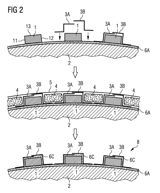
Fig. 2 illustrates steps of the inventive method of mounting
a magnet 1 to a rotor 2. In a first stage, as shown in the
top of the diagram, an adhesive layer 6A is applied to the
surface of the rotor 2, and the magnets 1 are positioned as
appropriate. Then, a pair of retainers 3A, 3B are put into
place, one on each side of the magnet 1, such that a first
retainer 3A lies alongside a first side face 11 of the magnet
1, and the second retainer 3B lies alongside the opposite
side face 12. The retainers 3A, 3B are dimensioned so that
they overlap on the upper side face 13 of the magnet 1.
Once all the magnets 1 have been covered by retainer pairs
3A, 3B, inserts 4 of thermoplastic material are placed be-
CA 02791808 2012-08-31
WO 2011/107168 PCT/EP2010/059399
tween adjacent magnets 1, as shown in the next stage. Then,
the entire arrangement of rotor 2, magnets 1, retainers 3A,
3B and inserts 4 is enclosed in a vacuum bag 5. During a vac-
uum extraction step, the adhesive 6A can be drawn into the
5 spaces between magnet 1 and retainer 3A, 3B. Additionally, an
epoxy resin adhesive 6C can be pumped into the vacuum bag by
means of a suitable nozzle (not shown in the diagram) and
distributed by negative pressure into any gaps and spaces be-
tween the magnets 1, the rotor 2 and the retainers 3A, 3B.
10 Heat may be applied to the entire assembly - for example in-
frared or UV radiation - to cure the adhesive 6A, 6C. Once
the adhesive 6A, 6C has hardened, the magnets 1, retainers
3A, 3B and rotor 2 are consolidated in a magnet mounting ar-
rangement 8, as shown in the lower part of the diagram. In
this way, the magnets 1 are protected from corrosion and me-
chanical impact b the retainers 3A, 3B, while also being
fixed firmly in place by the adhesive bond between retainers
3A, 3B and rotor 2.
Fig. 3 illustrates the steps of an alternative method accord-
ing to the invention. Here, the magnets 1 are spot-glued to
the rotor 2 using small amounts of adhesive 6B. Similarly,
retainer pairs 3A, 3B are spot-glued to the corresponding
magnet 1 and/or the rotor 2 as shown in the upper part of the
diagram. In this way, the magnets 1 and retainers 3A, 3B are
provisionally held in place. Inserts 4 of thermoplastic mate-
rial can then be laid into place between adjacent magnets 1,
and the entire assembly - magnets 1, retainers 3A, 3B, in-
serts 4 and rotor 2 - can be enclosed in a vacuum bag 5, as
shown in the next stage. Again, a vacuum extraction step is
then performed, in which an adhesive resin 6C is drawn into
any spaces between magnets 1, rotor 2 and retainers 3A, 3B in
a VART process. After the resin 6C has cured, the vacuum bag
5 and inserts 4 are removed to expose the consolidated magnet
mounting arrangement 8, as shown in the lower part of the
diagram, in which the magnets 1 are securely fastened to the
rotor 2 and protected from corrosion by the retainers 3A, 3B.
CA 02791808 2012-08-31
WO 2011/107168 PCT/EP2010/059399
11
Fig. 4 illustrates part of a magnet mounting arrangement ac-
cording to an embodiment of the invention. Here, a magnet 1
comprises several magnet elements 7, arranged in a staggered
manner on the basis of an optimisation of the performance of
the electrical machine of which the magnet 1 is a part. For
example, the staggered magnets 7 may serve to reduce the cog-
ging torque of the machine. The staggered arrangement of mag-
net elements 7 results in a wider overall width of the magnet
1. Therefore, retainers 3A, 3B are dimensioned accordingly so
that they overlap to cover the upper surfaces of all the mag-
net elements 7 parallel to the axis of rotation of the rotor
2, as shown in the plan view on the upper right of the dia-
gram. The vacuum extraction step is performed in the same way
as described above, with the use of inserts between the mag-
nets 1 if required, and any spaces between the magnet ele-
ments 7 and the retainers 3A, 3B can be filled with epoxy 6C
during the VART process. In this way, even such a complex ar-
rangement of magnet elements 7 can be easily and securely af-
fixed to the rotor 2 in a particularly straightforward and
economical manner.
Although the present invention has been disclosed in the form
of preferred embodiments and variations thereon, it will be
understood that numerous additional modifications and varia-
tions could be made thereto without departing from the scope
of the invention.
For the sake of clarity, it is to be understood that the use
of "a" or "an" throughout this application does not exclude a
plurality, and "comprising" does not exclude other steps or
elements.