Note : Les descriptions sont présentées dans la langue officielle dans laquelle elles ont été soumises.
81567522
1
DESCRIPTION
Semi-mounted reversible plow with rotary amplifier
The invention relates to a semi-mounted reversible plow.
Such a semi-mounted reversible plow can be taken from the European
patent specification EP 1 549 124. For this semi-mounted reversible plow there
is an
hydraulic cylinder placed between the attachment device and the plow frame.
This
hydraulic cylinder should contribute to improving the traction of the tractor.
If the front
axis of the tractor is to come under additional load, then a pressing force is
generated
via the hydraulic cylinder in the upper link of the tractor. If the rear axle
of the tractor
is to be put under load, EP 1 549 124 teaches that a tractive force must be
generated
in the upper link of the tractor. This prior art has the disadvantage that a
high torque
must be generated by the slewing gear during turning of the plow frame. The
slewing
gear must be designed to be appropriately extensive and heavy and is therefore
also
expensive. Also all neighboring components must be designed according to the
forces arising there, which also has a negative effect on the manufacturing
costs.
One further comparable semi-mounted reversible plow can be taken from EP 2 033
503. There is also an hydraulic cylinder provided here, as for the semi-
mounted
reversible plow according to EP 1 549 124, with which the tractive force in
the upper
link must be generated if the traction of the rear axle of the tractor should
be
increased through transfer of weight from the semi-mounted plow to the
tractor. This
is where the disadvantages occur, described above, concerning the high
rotational
energy required to a high degree since this design of semi-mounted reversible
plow
with just one wheel as the travel gear on the side on the frame requires a
significantly
higher rotational energy.
The object of the invention is to create an apparatus which reduces the
required rotational energy for turning the plow frame which holds the cost of
the
slewing gear within reasonable limits, which also increases the static
stability of the
=
CA 2798073 2017-07-20
81567522
2
tractor during the turning process and which also improves the traction of the
tractor
through transfer of weight from the semi-mounted plow to the tractor.
According to an aspect of the present invention, there is provided a
semi-mounted reversible plow comprising an attachment frame, wherein the
attachment frame has a plurality of link points wherein the link points have
an upper
link and lower links to attach the attachment frame to a tractor, a vertical
axis
connected to the attachment frame, an intermediate frame attached to the
vertical
axis and a plow frame pivotally attached to the intermediate frame, the plow
frame
carrying a plurality of plow bodies, wherein the plow frame is supported via a
travel
gear with at least one wheel, wherein the plow frame is turned into a
respective
operating position via a slewing gear having a rotational axis, a turning arm,
and a
cross-member, wherein the slewing gear is connected pivotably with the
intermediate
frame, and the intermediate frame is pivot-mounted in a horizontal direction
around
the upright standing axis and is overall rotationally freely connected for
trailing the
tractor and the attachment frame with the lower links, wherein a transverse
axis is
provided between the plow frame and the intermediate frame, and a hydraulic
cylinder is arranged above the transverse axis and is connected to the cross-
member
and to the intermediate frame, wherein weight of the semi-mounted reversible
plow
can be transferred to the tractor by the cross member, the hydraulic cylinder,
the
intermediate frame and the attachment frame, wherein a torque is applied onto
the
plow frame around the rotational axis, wherein the rotational axis of the
slewing gear
or an imaginary extension of the rotational axis is arranged to cross the plow
frame in
the operating position on a furrow side from the center of gravity of the plow
frame.
Another aspect provides a semi-mounted reversible plow with an
attachment frame with a plurality of link points for attachment to the upper
and lower
link of a tractor as well as a plow frame carrying a plurality of plow bodies
which is
supported via a travel gear with at least one wheel and is turned via the
slewing gear
with a rotational axis and turning arm into the respective operating position
and is
connected pivotably via an intermediate frame with the attachment frame pivot-
CA 2798073 2017-07-20
81567522
3
mounted in a horizontal direction, wherein a transverse axis is provided
between the
plow frame and the attachment frame which is arranged around the plow frame,
pivot-mounted in a vertical direction, and an hydraulic cylinder arranged at
some
distance from the transverse axis between the plow frame and attachment frame
with
which the weight of the semi-mounted reversible plow can be transferred to the
tractor, characterized in that the rotational axis of the slewing gear or the
imaginary
extension of the rotational axis is arranged to cross the plow frame in the
operating
position on the furrow side at some distance from the center of gravity of the
plow
frame.
Since the rotational axis or the imaginary extension of the rotational axis
crosses the plow frame in the operating position on the furrow side, at some
distance
from the center of gravity of the plow frame, the center of gravity of the
plow frame
lies between the rotational axis or the imaginary extension of the rotational
axis and
the rotational joint of the travel gear or wheel. Upon actuation of the
hydraulic cylinder
the weight of the semi-mounted reversible plow is transferred to the tractor
and
therefore a torque is applied onto the plow frame around the rotational axis.
Since the
center of gravity of the plow frame is arranged to the side of the rotational
axis or the
imaginary extension of the rotational axis between the wheel and the
rotational axis
or the imaginary extension of the rotational axis, actuation of the hydraulic
cylinder
causes turning of the plow frame if the tractive force in the hydraulic
cylinder is made
appropriately large. An appropriately low tractive force in the hydraulic
cylinder does,
on the other hand, only cause a reduction in the required torque which must be
delivered by the slewing gear. The magnitude of the reduction in the required
torque
depends on the distance between the center of gravity of the plow frame and
the
imaginary extension of the rotational axis and the part of the weight taken on
by the
hydraulic cylinder. The required torque from the slewing gear and therefore
also the
size of the hydraulic cylinder of the slewing gear can then be reduced and the
stability
of the tractor during the turning process increased by this magnitude of the
reduction
in the required torque. In this way, on the one hand, a weight is transferred
from the
CA 2798073 2017-07-20
81567522
4
device to the tractor to obtain better traction and the torque from the
slewing gear
required for the turning process of the plow frame is reduced significantly.
In some embodiments, the rotational axis or the imaginary extension of
the rotational axis is arranged to cross the plow frame in the front area in
the
operating position. Since the rotational axis or the imaginary extension of
the
rotational axis crosses the plow frame in the front area, the distance to the
center of
gravity of the plow frame is relatively large and therefore also the effective
lever arm
which, together with the lifting force of the hydraulic cylinder, causes
reduction of the
required torque of the slewing gear for the turning process of the plow frame.
In some embodiments, an enlargement of the lever arm is achieved in
such a way that the slewing gear or the imaginary extension of the rotational
axis is
arranged so as to cross the plow frame in the operating position in the area
between
the first plow body and the third plow body. The reduction in the required
torque
which must be delivered by the slewing gear for turning the plow frame is
increased
even further in this way.
In some embodiments, a draw frame is connected with the attachment
frame or with the intermediate frame which is connected in the rear area of
the plow
frame indirectly or directly with the plow frame or the travel gear. The plow
frame with
the bodies arranged on it is therefore pulled over the connecting point of the
turning
arm of the slewing gear with the plow frame and the connecting point of the
draw
frame with the plow frame or the travel gear. This effects a favorable
introduction of
the tractive forces into the plow frame.
In some embodiments, the draw frame is connected cardanically with
the attachment frame or with the intermediate frame and the travel gear and is
designed to serve as a torsion resistant stabilizer for fixing the upright
position of the
wheel. In cases where the travel gear just consists of one wheel then the
wheel can
be fixed and guided in its upright position using the known method.
CA 2798073 2017-07-20
81567522
According to another aspect of the present invention, there is provided
a semi-mounted reversible plow comprising an attachment frame, wherein the
attachment frame has a plurality of link points having upper and lower links
to attach
a tractor, a vertical axis connected to the attachment frame, and an
intermediate
5 frame connected to the a vertical axis, a plow frame connected to the
intermediate
frame, the plow frame carrying a plurality of plow bodies, wherein the plow
frame is
supported via a travel gear with at least one wheel, wherein the plow frame is
turned
via a slewing gear with a rotational axis and turning arm into an operating
position of
the plow frame, and wherein the plow frame is connected pivotably with the
intermediate frame and is pivot-mounted in a horizontal direction, wherein the
rotational axis of the slewing gear or an imaginary extension of the
rotational axis is
arranged to cross the plow frame in the operating position on a furrow side
from a
center of gravity of the plow frame and the plow bodies, and wherein the upper
link is
a hydraulic cylinder with which weight of the semi-mounted reversible plow can
be
transferred to the tractor by a lifting torque applied to the attachment
frame.
Another aspect provides a semi-mounted reversible plow with an
attachment frame with a plurality of link points for attachment to the upper
and lower
link of a tractor as well as a plow frame carrying a plurality of plow bodies,
which
frame is supported via a travel gear with at least one wheel and is turned
over the
slewing gear with a rotational axis and turning arm into the respective
operating
position and is connected pivot-mounted with the attachment frame in a
horizontal
direction, for which the rotational axis of the slewing gear or the imaginary
extension
of the rotational axis crosses the plow frame in the operating position on the
furrow
side at some distance from the center of gravity of the plow frame and for
which the
upper link is designed as an hydraulic cylinder. For this solution, transfer
of weight of
the semi-mounted reversible plow to the tractor is not via an hydraulic
cylinder
integrated on the semi-mounted reversible plow but rather via an hydraulic
cylinder
designed as an upper link which is arranged between the attachment frame and
the
tractor. This solution somewhat simplifies the structure of the plow and also
offers the
option to achieve a comparable effect using less effort overall, as with the
version
CA 2798073 2017-07-20
81567522
5a
with the hydraulic cylinder integrated in the semi-mounted reversible plow
according
to the first aspect of the invention and embodiments thereof described above.
It is
also possible for this solution to have the position of the rotational axis or
the position
of the imaginary extension of the rotational axis similarly arranged on the
furrow side
to cross the plow frame at some distance from the center of gravity of the
plow frame.
Further details and advantages of the subject of some embodiments of
the invention emerge from the following description and the relevant drawings,
which
show two exemplary embodiments with the necessary details and single parts.
Figure 1 shows a side view of the semi-mounted reversible plow in its
operating position,
Figure 2 shows a view from above of the semi-mounted reversible plow
in its operating position,
Figure 3 shows a cut-out of the side view of the front part of the semi-
mounted reversible plow according to Figure 1, and
Figure 4 shows a side view of the semi-mounted reversible plow in its
operating position with an hydraulic cylinder functioning as the upper link.
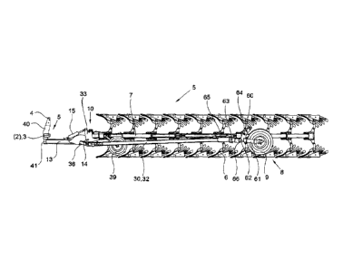
Figure 1 shows a side view of the semi-mounted reversible plow 1 in its
operating position. The semi-mounted reversible plow 1 comprises the main
components attachment frame 5, slewing gear 10, travel gear 8, draw frame 30
and
plow frame 7 with the plow bodies 6. The semi-mounted reversible plow 1 is
connected with the three-point rod of a tractor via the attachment frame 5.
The upper
link pivot 4 and the lower link pivots 2 and 3 are provided for this on the
attachment
frame 5. The attachment frame 5 with its attachment tower 40 has the upright
standing axis 41 with which the plow frame 7 and the travel gear 8 are
connected
pivotably via the intermediate frame 13. The transverse axis 14 is provided on
the
intermediate frame 13 on the end-side via which the slewing gear 10 is
connected
pivotably with its cross-member 33. The hydraulic cylinder 15 is connected at
some
CA 2798073 2017-07-20
81567522
5b
distance from the transverse axis 14 with the cross-member 33 and the
intermediate
frame 13. Upon actuation the hydraulic cylinder 15 transfers the weight of the
plow
frame 7 to the attachment frame 5 and therefore to the rear axle of the
tractor (not
shown). To this effect, the hydraulic cylinder 15 is fitted with one or a
multiplicity of
hydraulic accumulators (not shown here) which allow adaptation to the ground
of the
plow frame 7 with the plow bodies 6 while
CA 2798073 2017-07-20
CA 02798073 2012-11-01
6
maintaining the transfer of weight of the plow frame to the tractor. The plow
bodies
6 are led at operating depth, at the front, by means of the tracing wheel 39
and, at
the rear, by means of the travel gear 8 with wheel 9. The cross-member 33
receives the rotational axis 11 and the turning arm 12 which can be seen
particularly clearly in Figure 2. The travel gear 8 is in connection via the
draw
frame 30 with the attachment frame 5. The draw frame 30 serves in this case as
a
torsion resistant stabilizer 32 which is connected cardanically via the
intermediate
link 36 and the intermediate frame 13 with the attachment frame 5. The draw
frame 30 or the stabilizer 32 are connected cardanically in the rear area 31
of the
semi-mounted reversible plow 1 via the rear transverse axis 62 and the upright
axis 63 with the wheel carrier 60, which is pivoted via the hydraulic cylinder
64
around the rear transverse axis 62, wherein the operating depth of the plow
bodies
6, amongst other things, can also be changed. The range of swivel of the wheel
carrier 60 around the rear transverse axis 62 is limited by a dead stop 66 to
secure
clearance above the ground. The length of the draw frame 30 and therefore also
the front furrow width of the semi-mounted reversible plow 1 can be altered by
means of the actuator 65 in the normally known manner. The wheel carrier 60
has
the wheel fork 61 in which the wheel 9 is mounted.
Figure 2 shows a view from above of the semi-mounted reversible plow 1 in
its operating position. The semi-mounted reversible plow 1 is overall freely
connected around the upright standing axis 41 trailing with the tractor via
the
attachment frame 5 and the upper link pivot 4 and the lower link pivots 2, 3.
The
intermediate frame 13 is connected with the upright standing axis 41 which
receives the cross-member 33 of the slewing gear 10 with the rotational axis
11
and the turning arm 12. Owing to the particular arrangement of the slewing
gear
10, the rotational axis 11 is in a position which ensures that the imaginary
extension 16 of the rotational axis 11 crosses the plow frame 7 on the furrow
side
at some distance 17 from the center of gravity 18 as seen in the direction of
the
extension 16 of the rotational axis 11. In order to achieve the effect of
reducing the
required rotational energy, the imaginary extension 16 of the rotatiorrafaxis
11
must cross the plow frame 7 in the front area 20. In the example according to
CA 02798073 2012-11-01
7
Figure 2 the imaginary extension 16 of the rotational axis 11 crosses the plow
frame 7 in the area 21, between the first plow body 22 and the third plow body
23.
The semi-mounted reversible plow 1 is a semi-mounted reversible plow 1 with a
variable operating width adjustment plow body 6. Actuation of the hydraulic
cylinder 42 causes the operating width of the individual plow bodies 6 to be
altered
via the control gear 59. Here, also the wheel arm 57 with the pivot bearing 58
and
therefore also the travel gear 8 are adjusted with the wheel 9 in a direction
parallel
to the direction of operation. The wheel arm 57 with the pivot bearing 58 is
connected at the rear of the plow frame 7 with the plow frame 7 via the
console 55.
Actuation of the hydraulic cylinder 42 causes both the position of the plow
frame 7
and the position of the draw frame 30 and the intermediate frame 13 to change.
This change in the position of the intermediate frame 13 also causes a change
in
the position of the imaginary extension 16 of the rotational axis 11 and
therefore
also the distance 17 of the imaginary extension 16 of the rotational axis 11
to the
center of gravity 18. One ensures that the imaginary extension 16 of the
rotational
axis 11 is always on the furrow side some distance 17 from the center of
gravity 18
in every operating width setting. The reduction in the required rotational
energy for
the slewing gear 10 is optimal if the distance 17 is very large and the
lifting force of
the hydraulic cylinder 15 is also very large. Conversely, the reduction in the
required rotational energy for turning the slewing gear 10 is lower if the
lifting force
of the hydraulic cylinder 15 is reduced and the distance 17 is smaller. A
reduction
in the required rotational energy is not possible if the lifting force of the
hydraulic
cylinder 15 is zero or if the imaginary extension 16 of the rotational axis 11
runs
through the center of gravity 18 or on the land side of the center of gravity
18. On
the land side means the area 43 which is in the right turning plow position of
the
semi-mounted reversible plow 1 on the left of the center of gravity 18 of plow
frame 7.
Figure 3 shows a cut out of a side view of the front part of the semi-
mounted reversible plow 1. The hydraulic cylinder 15 is, on the one hand,
connected to the mounting point 35 of the cross-member 33 and, on the other
hand, with the mounting point 34 of the intermediate frame 13. The hydraulic
CA 02798073 2012-11-01
8
cylinder 15 is arranged here at some distance from the transverse axis 14. The
greater the distance apart, the more the weight can be transferred from the
plow
frame 7 to the tractor for the same lifting force or tractive force of the
hydraulic
cylinder 15. Figure 3 also clearly illustrates the arrangement of the
intermediate
link 36 which connects the draw frame 30 or the stabilizer 32 cardanically
with the
intermediate frame 13. To this effect, the intermediate link 36 has the
vertical axis
of traction 37 and the horizontal axis of traction 38.
Figure 4 shows an alternative solution, without the hydraulic cylinder 15
according to Figure 1. A trailing arm 52 is used here instead of the hydraulic
cylinder 15 which blocks a movement around the axis 14 of the intermediate
frame
13 to the cross-member 33. The intermediate frame 13 and the cross-member 33
can also form a unit permanently attached to each other so that the transverse
axis 14 and the trailing arm 52 are not needed. Then, the transfer of the
weight of
the plow frame 7 to the tractor takes place via the upper link which, in this
case, is
designed as an hydraulic cylinder 50. The lower links 51 are integral parts of
the
tractor. The hydraulic cylinder 50 is an integral part of the plow. Movability
of the
hydraulic cylinder 50 can be achieved via the hydraulic accumulators (not
shown
here), wherein an adaptation to the ground can be secured between the tractor
and the semi-mounted reversible plow 1 while maintaining the tractive force in
the
hydraulic cylinder 50.
The lifting force or the tractive force of the hydraulic cylinders 15 or 50,
both
for the design according to Figure 1 to 3 and also the design according to
Figure 4,
can be controlled using a control apparatus, for example dependent on the slip
of
the drive wheels on the tractor or with a pre-set regulating variable for the
tractive
force or the lifting force of the respective hydraulic cylinder 15 or 50.