Note : Les descriptions sont présentées dans la langue officielle dans laquelle elles ont été soumises.
1
TRUCK BED EXTENSION
This invention is in the field of devices for extending the cargo bed of a
truck.
BACKGROUND
A modern pickup truck typically has either a six foot or an eight foot bed. In
sonic cases, it is desirable to have a longer bed length to transport certain
loads that do
not fit within the bed length. There are a number of truck bed extenders known
that
allow a user to extend the capacity of his or her truck bed. Typically, these
truck bed
extenders operate by having the user fold down the tailgate on his or her
truck and then
providing some sort of structure that surrounds the tailgate so that the
tailgate of the truck
becomes part of the cargo bed.
However, a truck tailgate is not very strong and is not designed to handle as
much
weight as the bed of the truck. The tailgate is typically hinged on the bottom
so that it
can pivot between an open position, where the tailgate lies flat so that the
bed of the truck
can be loaded, and a closed position, where it closes the back of the bed of
the truck.
When the tailgate is in the closed position, it is secured in an upright
position by the
hinges and latches that mate with the sides of the bed. However, when the
tailgate is
lying flat in the open position, it is only secured in place by the two hinges
and typically a
relatively thin steel cord to keep it from pivoting any further around the
hinges. Because
of the configuration of the tailgate, the tailgate is substantially weaker
than the bed of the
truck. When a load is placed on a tailgate that is in the open position, the
cord and hinges
are all that is supporting the load. This can create problems with bed
extending structures
that use the tailgate to extend the bed length.
Additionally, it has become common to carry all terrain vehicles (ATVs) and
other personal recreational vehicles in the bed of trucks. These personal
recreational
vehicles can be quite heavy. Not only can they place substantial weight on the
tailgate of
a truck when the tailgate is left in an open position to support a portion of
the recreational
CA 2804270 2017-11-02
2
vehicle, but they can also place substantial weight on the tailgate when a
ramp is used to
load the vehicle into the bed of a truck. Often, a ramp is used to load these
vehicles or
other loads into the bed of the truck, with the ramp being positioned with one
end on the
lowered tailgate and the other end of the ramp on the ground. As the
recreational vehicle
is being driven up the ramp, the weight of the vehicle forces the ends of the
ramp against
the open tailgate transferring the weight of the load to the tailgate, which
in turn is only
supported by a thin steel cord.
SUMMARY OF THE INVENTION
In one aspect, an apparatus for extending a bed of a truck is provided. The
apparatus comprises a load platform extending substantially outwards from a
bed of the
truck when the load platform is in position, the load platform having a
proximal end and
a distal end; and a hitch assembly having a connection arm for insertion into
a hitch
receiver on the truck and a support ann extending upwards to support at least
some of the
weight of the load platform.
In another aspect, a method of installing a bed extender on a truck is
provided.
The method comprises: removing a tailgate of truck; inserting a hitch assembly
into a
hitch receiver on the truck; and positioning a load platform connected to the
hitch
assembly so that the load platform extends from the bed of the truck.
In another aspect, a drawbar can be provided on the hitch assembly to allow a
trailer to be connected to the hitch assembly.
CA 2804270 2017-11-02
3
DESCRIPTION OF THE DRAWINGS
While the invention is claimed in the concluding portions hereof, preferred
embodiments are provided in the accompanying detailed description which may be
best
understood in conjunction with the accompanying diagrams where like parts in
each of
the several diagrams are labeled with like numbers, and where:
Fig. 1 is a perspective view of a bed extender;
Fig. 2 is a side view of the bed extender of Fig. 1;
Fig. 3 is a side view of the bed extender of Fig. 1 with a tailgate enclosure
pivoted
into an open position;
Fig. 4 is a perspective view of an alternative version of a hitch receiver;
Fig. 5 is a perspective view of the bed extender with ramps attached;
Fig. 6 is a side view of a bed extender with supports for the tailgate
enclosure;
Fig. 7 is a side view of the bed extender of Fig. 6 with support holding the
enclosure tailgate in position;
Fig. 8 is a side view of the bed extender with the tailgate enclosure held in
place
with braces; and
Fig. 9 is a partial view of a compression assembly and a tensioner assembly
used
to hold the load platform in place relative to a bed of a truck.
CA 2804270 2017-11-02
4
DETAILED DESCRIPTION OF THE ILLUSTRATED EMBODIMENTS
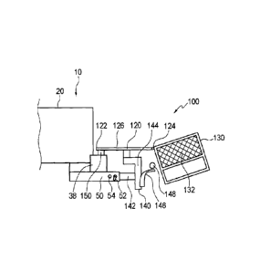
Figs. 1 and 2 illustrate a bed ex-tender 100 for use with a truck 10 to extend
the
bed 20 of the truck 10. The bed extender 100 can have a load platform 120, a
tailgate
enclosure 130, and a hitch assembly 140.
The load platform 120 can extend substantially outwards from the floor 22 of
the
bed 20 of the truck 10 to create a cargo area defined by the bed 20 of the
truck 10 and the
load platform 120. The load platform 120 can have a proximate end 122, a
distal end 124
and support surface 126. "lhe proximate end 122 of the load platform 120 can
be
positioned adjacent to the end 24 of the bed 20 of the truck 1() when the bed
extender 100
is installed on the truck 10 so that the load platform 120 is in a position
similar to the
position a lowered tailgate would be in.
The load platform 120 can be formed of steel plate, metal mesh or any other
suitable material.
A hitch assembly 140 can be provided to support the load platform 120 in place
adjacent to the floor 22 of the bed 20 of the truck 10. The hitch assembly 140
can have a
connection arm 142 for insertion into a hitch receiver 50 provided on the
truck 10. The
hitch receiver 50 can be a standard hitch receiver 50 as is known in the art.
A support
member 144 can extend upwards from the connection arm 142 to support the load
platform 120 in place.
In this manner, rather than using the tailgate hinges and a cord (not shown)
to
keep the load platform 120 in place, weight placed on the load platform 120
can be
transferred to the hitch receiver 50 of the truck 10 which is designed to
accept a tongue
weight when towing a trailer (not shown). The hitch assembly 140 holds the
load
platform 120 in a fixed and rigid relation to the hitch receiver 50 so that
the load platform
120 can not pivot or move substantially vertically relative to the hitch
receiver 50 when
the connection arm 142 is secured in the hitch receiver 50.
CA 2804270 2017-11-02
The hitch assembly 140 can be constructed so that it transfers all of the
weight
placed on the load platform 120 to the hitch receiver 50. Alternatively, in
one. aspect,
pads 150, made of rubber, etc. can be placed under the load platform 120 so
that the pads
150 rest on the rear bumper 38 of the truck 10 when the bed extension 100 is
in use and
the load platform 120 is positioned adjacent the bed 20 of the truck 10. In
this manner,
any weight placed on the load platform 120 is supported by both the hitch
receiver 50 and
the rear bumper 38 of the truck 10.
The hitch assembly 140 can also include a drawbar 146 that can be used to pull
a
trailer (not shown), such as by using the drawbar 146 in conjunction with a
hitch ball 148.
In one aspect, the hitch assembly 140 can provide various height mounts so
that the draw
bar 146 can be set at different heights relative to the rest of the hitch
assembly 140.
Referring to Fig. 4, an alternate hitch assembly 240 can be used. Hitch
assembly
240 can also be used to support the load platform 120 in place adjacent to the
floor 22 of
the bed 20 of the truck 10. The hitch assembly 240 can have a connection arm
242 for
insertion into a hitch receiver (not shown). A support member 244 can extend
upwards
from the connection aim 242. A first extendable member 246 can be provided
slidably
mounted relative to the support member 244 so that the first extendable member
246 can
be moved horizontally relative to the support member 244. A second extendable
member
228 can be provided slidably mounted relative to the first extendable member
246, so that
the second slidable member can be moved vertically relative to the first
extendable
member 246 and the connection arm 242. If the load platform 120 is operatively
connected to the second slidable member 248, the load platform 120 can be
moved
vertically relative to a hitch receiver the hitch assembly 240 is inserted in
by moving the
second extendable member 248 up or down and the load platform 120 can be moved
horizontally relative to the hitch receiver the hitch assembly 240 is inserted
in by moving
the first extendable member 246 horizontally.
In one aspect, the horizontal and vertical positioning of the load platform
120
relative to the hitch receiver 50 can be done by providing a first sleeve 245
through with
CA 2804270 2017-11-02
6
the first extendable member 246 slides through and a second sleeve 247 through
which a
second extendable member 248 slides through. A first aperture 252 can be
provided in
the first sleeve 245 that can be aligned with any of a series of apertures 246
in the first
extendable member 246 so that the position of the first extendable member 246
can be
fixed by sliding a pin or other member through the aligned apertures 252, 254.
A second
aperture 256 can provided in the second sleeve 247 that can be aligned with
any of series
of apertures 258 in the second extendable member 248. The second extendable
member
248 can be fixed in a vertical position relative to the second sleeve 247 by
aligning the
aperture 256 with an aperture 258 in the second sleeve 247 and inserting a pin
or other
member through the aligned apertures 256, 258.
Referring again to Figs. 1 and 2, a tailgate enclosure 130 can be pivotally
connected to the distal end 124 of the load platform 120. The tailgate
enclosure 130 can
be used to confine cargo to the extended cargo area defined by the bed 20 of
the truck 10
and the load platform 120. In one aspect, side sections 132 can be provided on
the
tailgate enclosure 130 so that they run substantially along sides of the load
platfomi 120.
The side sections 132 can prevent any cargo placed in the bed 20 of the truck
10 or on the
load platform 120 from falling off the sides of the load platform 120.
The tailgate enclosure 130 can be pivoted between a closed position and an
open
position. In the closed position, the tailgate enclosure 130 is pivoted
upwards, as shown
in Figs. 1 and 2, and secured in this upright position to enclose cargo in the
bed 20 of the
truck 10 and the load platform 120. In the open position, the tailgate
enclosure 130 is
pivoted downwards around the distal end 124 of the load platform 120 as shown
in Fig. 3.
This allows a person access to the bed 20 of the truck 10 and cargo can be
loaded into the
cargo area defined by the bed 20 of the truck 10 and the load platform 120 by
passing it
over top of the tailgate enclosure 130 which is pivoted downwards into its
open position.
In one aspect, the tailgate enclosure 130 can be pivoted downwards below the
level of the load platform 120 so that ramps 160, as shown in Fig. 4, can be
used to load
cargo such as personal recreational vehicles and other cargo into the cargo
area defined
CA 2804270 2017-11-02
7
by the bed 20 of the truck 10 and the load platform 120. First ends 162 of the
ramps 160
can be placed on or attached to the distal end 124 of the load platform 120
while the
second ends 164 of the ramps 160 can be placed on the ground. Cargo can be
moved up
the ramps 160 and loaded into the cargo area defined by the bed 20 of the
truck 10 and
the load platform 120.
When cargo is being moved up the ramps 160 to be loaded into the cargo area
defined by the bed 20 of the truck 10 and the load platform 120, the force of
the cargo
exerted the ramps 160 is at least partially transferred through the first ends
162 of the
ramps 160 to the distal end 124 of the load platform 120 where this force is
.in turn
transferred through the load platform 120 to the hitch receiver 50 (and the
rear bumper 38
of the truck 10 if the pads 150 are used).
In other circumstances, it may be desirable to have the tailgate enclosure 130
so
that it does not pivot down below the level of the support surface 126 of the
load platform
120 but rather forms an extension of the load platform 120 as shown in Fig. 8.
Braces
205 can be provided connected between a bottom corner 136 of the tailgate
enclosure 130
and the load platform 120 to secure the tailgate enclosure 130 in this
position.
Referring to Figs. 1 and 2, to install the bed extender 100, the tailgate (not
shown)
of the truck 10 can be removed from the truck 10. This is typically done by
disconnecting the cord (not shown) and removing the hinges of the tailgate
from the
hinges in the sides of the bed 20 of the truck 10. With the tailgate removed,
the hitch
assembly 140 can be attached to the truck 10 by inserting the connection arm
142 into the
hitch receiver 50 on the truck 10. Typically, a hitch pin 52 is slid through
an aperture 54
in the hitch receiver 50 that is aligned with an aperture in the connection
arm 142 of the
hitch assembly 140. By inserting the connection arm 142 of the hitch assembly
140 into
the hitch receiver 50 and securing it in place, the proximate end 122 of the
load platform
120 can be positioned adjacent the end 24 of the floor 22 of the bed 20 of the
truck 10.
=
CA 2804270 2017-11-02
8
With the hitch assembly 140 connected to the hitch receiver 50 and the load
platform 120 positioned adjacent to the bed 20 of the truck 10, the tailgate
enclosure 130
can be placed in its upright position and secured in place.
If the hitch assembly 140 includes a draw bar 146, the draw bar 146 can be set
to
the desired height.
In operation, the bed extension 100 can be used to extend the amount of cargo
space in the bed 20 of the truck 10. Rather than being limited to just the
floor 22 of the
bed 20 of the truck 10, the bed extension 100 allows cargo to extend onto the
load
platform 120. The weight of any cargo on the load platform 120 is borne by the
hitch
receiver 50 of the truck 10 (and the rear bumper 38 if the load platform 120
is provided
with pads 150).
To load the cargo area of the truck 10, the tailgate enclosure 130 can be
moved
from its upright closed position to its open position by pivoting the tailgate
enclosure 130
around the distal end 124 of the load platform 120 allowing access to the
cargo area of
the truck 10. With the tailgate enclosure 130 in its open position, a user can
then load
cargo onto the bed 20 of the truck 10 and the load platform 120. When the
truck 10 has
been loaded, the tailgate enclosure 130 can be swung back up into its upright
closed
position and secured in this position. With the tailgate enclosure 130 in its
upright closed
position, the tailgate enclosure 130 will prevent any of the cargo loaded in
the cargo area
from falling off the distal end 124 of the load platform 120 and the side
sections 132 of
the tailgate enclosure 130 will prevent any cargo from falling off of the
sides of the load
platform 120. With the cargo secured in the cargo area by the tailgate
enclosure 130, the
truck 10 is then ready to haul the cargo.
Referring to Fig. 5, if a personal vehicle, such as an ATV, snowmobile," etc.
or
other heavy cargo is being loaded onto the bed 20 of the truck 10 and the load
platform
120, ramps 160 can be used to load the truck 10. The tailgate enclosure 130
can be
pivoted down into its open position and the ramps 160 can be placed with their
first ends
=
CA 2804270 2017-11-02
9
162 on or attached to the load platform 120. The load can then be moved up or
driven up
the ramps 160 onto the load platform 120 and onto the floor 22 of the bed 20
of the truck
10. The ramps 160 can then be removed and the tailgate enclosure 130 pivoted
upwards
into its closed position and secured in place enclosing the cargo in the cargo
area.
Figs. 6 and 7 illustrate the bed extender 100 with support mounts 170 and
extension members 172 to support the tailgate enclosure 130 in an open
position.
Support mounts 170 can be positioned beneath the load platform 120. These
support
mounts 170 can be positioned so that they are extending towards the distal end
124 of the
load platform 120, but not extending beyond the distal end 124 of the load
platform 120.
In one aspect, the support mounts 170 can be square or rectangular tubing.
Extension members 172 can be provided. The extension members 172 can be
hollow and have the same cross-sectional shape as the support mounts 170 only
with
slightly larger dimensions so that they can slide over the support mounts 170.
The
extension members 172 can be substantially longer than the support mounts 170
so that
when the extension members 172 are slid in place over the support mounts 170,
the
extension members 172 extend beyond the distal end 124 of the load platform
120.
Referring to Fig. 6, the tailgate enclosure 130 can be moved into its open
position.
Rather than the tailgate enclosure 130 being free to pivot downwards below the
load
platform 120, as shown in Fig. 3, the tailgate enclosure 130 comes into
contact with the
extension members 172 can be supported in position by the extension members
172 and
the support mounts 170. In one aspect, the extension members 172 and support
mounts
170 can be positioned so that the tailgate enclosure 130 is held in a position
substantially
horizontally by the extension members 172.
In this manner, if force is placed on the tailgate enclosure 130 when it is in
the
open position, such as when cargo is placed on the tailgate enclosure 130,
ramps are
placed on the tailgate enclosure 130, etc., this force is transferred through
the extension
CA 2804270 2017-11-02
10
members 172, the support mounts 170 and the hitch assembly 140 to the hitch
receiver
SO.
In another aspect, extension members 172 can be telescopically connected to
the
support mounts 170 so that they can be retracted under the load platform 120
so that the
extension members 172 are not extending beyond the distal end 124 of the load
platform
120 and the extended into an extended position where they are extending out
past the
distal end 124 of the load platform 120 to support the tailgate enclosure 130
in the open
position.
In one aspect, a compression assembly 300 can be provided to help secure the
load platform 120 relative to the bed 20 of the truck 10. Referring to Fig. 9,
in one
aspect, the compression assembly 300 can include a threaded rod 302 with a
contact end
304. The contact end 304 could be made of a mildly compressible material and
is placed
in contact with the end 24 of the bed 20 of the truck 10. The threaded rod 302
can be
threaded into a mating threaded aperture 310 on the load platform 120. A nut
306 can be
provided on the threaded rod 302 between the contact end 304 of the threaded
rod 302
and the load platform 120.
In operation, the compression assembly 300 can be rotated in the threaded
aperture 210 until the contact end 304 of the compression assembly 300 is
securely
pressed against an end 24 of the bed 20 of the truck 10, forcing the load
platform 120
away from the bed 20 of the truck 10. The nut 306 can then be threaded along
the
threaded rod 302 until it is snugged against the threaded aperture 310. In
this manner, the
load platform 120 can be forced away from the bed 20 of the truck and against
the front
of the hitch assembly 140 preventing the load platform 120 from moving.
A tensioner assembly 350 can be also provided to pull the load platform 120
towards the bed 20 of the truck 10. A first end 352 of the tensioner assembly
350 could
be connected to or inside the bed 20 of the truck 10 while a second end 354
,can be
connected to the load platform 120. This tensioner assembly 350 can be pulling
the load
CA 2804270 2017-11-02
11
platform 120 towards the bed 20 of the truck 10. In one aspect, the tensioner
assembly
350 could be a turn buckle to allow a user to tighten the tensioner assembly
350, pulling
the load platform 120 towards the bed 20 of the truck. 10.
The compression assembly 300 and the tensioner assembly 350 can act in
conjunction with the compression assembly 300 pushing the load platform 120
away
from the bed 20 of the truck 10 while the tensioner assembly 350 pulls the
load platform
120 towards the bed 20 of the truck 10. The compression assembly 300 and the
tensioner
assembly 350 acting in conjunction can hold the load platform 120 solidly in
place.
The foregoing is considered as illustrative only of the principles of the
invention.
Further, since numerous changes and modifications will readily occur to those
skilled in
the art, it is not desired to limit the invention to the exact construction
and operation
shown and described, and accordingly, all such suitable changes or
modifications in
structure or operation which may be resorted to are intended to fall within
the scope of
the claimed invention.
CA 2804270 2017-11-02