Note : Les descriptions sont présentées dans la langue officielle dans laquelle elles ont été soumises.
CA 02813452 2013-04-19
,
HOLE SAW KIT
FIELD OF THE INVENTION
[0001] The present invention relates to kits and like devices for holding
tools, and
more particularly, relates to kits and like devices for holding hole saws.
BACKGROUND INFORMATION
[0002] Tradesmen, such as plumbers, electricians, and heating, ventilating
and air
conditioning ("HVAC") technicians, can struggle with the weight and size of
tools and
supplies they must bring to worksites. This difficulty is exasperated by the
desire to
bring to worksites all tools and supplies that might possibly be needed to
eliminate
potentially wasteful time spent on multiple trips back and forth to the
worksite to bring in
additional tools and supplies. As a result, tradesman may overload their tool
bags and
boxes with heavy and awkward tools in an effort to bring as many tools and
supplies as
possible to worksites. Hole saws and hole cutters (collectively referred to
herein as
"hole saws"), arbors for driving the hole saws, and related tools and
accessories, such
as pilot drill bits, can be loosely packed into traditional tool kits, bags or
boxes, taking up
significantly more volume than desired and making it difficult to find the
individual holes
saws, arbors or other accessories when needed.
[0003] It is an object of the present invention to overcome one or more of
the above-
described drawbacks and/or disadvantages of the prior art.
1
CA 02813452 2013-04-19
SUMMARY OF THE INVENTION
[0004] In accordance with one aspect, the present invention is directed to
device for
carrying hole saws comprising a hole saw carrier configured to releasably
carry thereon
a plurality of nested hole saws, and movable between (i) a storage position
and (ii) a
use position for removing one or more hole saws therefrom. In some embodiments
of
the present invention, the carrier is axially-elongated and receivable through
an arbor
hole in a hole saw to releasably carry the hole saw thereon and to allow one
hole saw to
be nested within another thereon. In some such embodiments, the axially-
elongated
carrier is pivotally mounted on the device and pivotable between the storage
and use
positions.
[0005] In some embodiments of the present invention, the carrier is
retracted within
the device in the storage position, and the carrier extends from the device in
the use
position to facilitate the release of hole saws therefrom. In some such
embodiments, in
the use position the carrier is substantially upright.
[0006] In some embodiments of the present invention, the device defines a
recess
that receives at least part of the carrier and any hole saws carried thereon
in the storage
position. In some such embodiments, the recess defines a plurality of
different width
recessed portions. Each such portion corresponds to the diameter of a
respective size
hole saw for receiving at least part of the hole saw of the respective size
therein in the
storage position. Preferably, the different width recessed portions define
progressively
more narrow widths relative to each other in an axial direction of the carrier
for receiving
therein a plurality of nested hole saws in the storage position.
2
CA 02813452 2013-04-19
. .
,
,
[0007] In some embodiments of the present invention, the device includes a
base
and a cover. The base and/or cover is movable relative to the other between
open and
closed positions. In the closed position the carrier is in the storage
position and is
substantially prevented from movement into the use position, and in the open
position
the carrier is movable between the storage and use positions. In some such
embodiments, the base defines a first recess for receiving a first portion of
the carrier
and/or any hole saws carried thereon in the storage position, and the cover
defines a
second recess for receiving a second portion of the carrier and/or any hole
saws carried
thereon in the storage position.
[0008] In some embodiments of the present invention, the base and/or cover
defines
a recess for receiving at least a portion of the carrier and any hole saws
carried thereon
in the storage position, and (i) at least one hole saw mount located laterally
relative to
the recess for releasably mounting a hole saw; (ii) at least one arbor mount
located
laterally relative to the recess for releasably mounting an arbor; and/or
(iii) at least one
pilot drill mount located laterally relative to the recess for releasably
mounting a pilot
drill. In some embodiments of the present invention, each mount frictionally
engages
the respective hole saw, arbor and/or pilot drill to releasably retain it
within the device.
In some embodiments (i) the at least one hole saw mount is defined by a
respective
hole saw recess located laterally relative to the first or second recess for
releasably
receiving at least a portion of at least one hole saw therein; (ii) at least
one arbor recess
is located laterally relative to the first or second recess for releasably
receiving at least a
portion of at least one arbor therein; and/or (iii) at least one pilot drill
recess is located
3
CA 02813452 2013-04-19
. .
,
,
laterally relative to the first or second recess for releasably receiving at
least a portion of
at least one pilot drill therein.
[0009] In accordance with another aspect, the present invention is directed
to a
device for carrying hole saws comprising first means for releasably carrying
thereon a
plurality of nested hole saws; and second means for moving the first means
between
(i) a storage position, and (ii) a use position for removing one or more hole
saws
therefrom.
[0010] In some embodiments of the present invention, the first means is an
axially-
elongated carrier receivable through an arbor hole in a hole saw to releasably
carry a
plurality of nested hole saws, and the second means is a pivot mount located
between
the carrier and device for pivoting the carrier on the device between the
storage and use
positions.
[0011] One advantage of the present invention is that the device allows
tradesmen
or other persons to store in a kit or like device a plurality of hole saws,
such as a
complete or typical set of hole saws, and if desired, associated arbors and/or
other
accessories, and to conveniently transport such hole saws, and if desired,
associated
arbors and other accessories, to and from worksites. Another advantage of the
present
invention is that the carrier allows the hole saws to be carried thereon in a
nested
arrangement which reduces the volume and/or footprint of the stored hole saws
and, in
turn, reduces the size of the kit or like device for holding and transporting
the hole saws.
Yet another advantage of the present invention is that the carrier can be
moved
between storage and use positions to easily install hole saws thereon for
storage, and
to remove holes saws therefrom for use. Yet another advantage is that the kit
4
CA 02813452 2013-04-19
, .
organizes and stores the hole saws in a nested arrangement thereby reducing
the
volume and footprint of the stored hole saws and facilitating quick and
convenient
retrieval of hole saws when needed for use.
[0012] Other objects and advantages of the present invention, and/or of the
currently
preferred embodiments thereof, will become more readily apparent in view of
the
following detailed description of the currently preferred embodiments and
accompanying
drawings.
BRIEF DESCRIPTION OF THE DRAWINGS
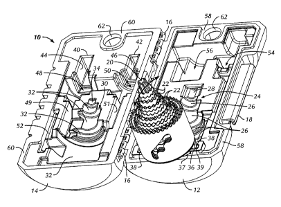
[0013] FIG. 1 is a perspective view of a hole saw kit embodying the present
invention
in the closed position.
[0014] FIG. 2 is a perspective view of the hole saw kit of FIG. 1 in the
open position
with the carrier in the extended or use position for removing therefrom or
installing
thereon one or more hole saws.
[0015] FIG. 3 is a perspective view of the hole saw kit of FIG. 1 in the
open position
with the carrier and hole saws omitted for clarity.
DETAILED DESCRIPTION OF CURRENTLY
PREFERRED EMBODIMENTS
[0016] In FIGS. 1-3, a device embodying the present invention is indicated
generally
by the reference numeral 10. The device 10 is a kit for storing hole saws, and
if
desired, for storing arbors for driving the hole saws and other tools or
accessories, such
as pilot drill bits. The kit 10 includes a base 12 and a cover 14 pivotally
mounted to the
base by a hinge 16. The base 12 includes a closure 18 of a type known to those
of
ordinary skill in the pertinent art that releasably engages the cover in the
closed position
CA 02813452 2013-04-19
to hold the cover closed, as shown in FIG. 1, but is movable to release the
cover from
the base and move the cover into the open position, as shown in FIG. 2.
[0017] As shown best in FIG. 2, the kit 10 includes a hole saw carrier 20
configured
to releasably carry thereon a plurality of nested hole saws 22, 22. As
indicated by the
arrow in FIG. 2, the carrier 20 is movable between (i) a storage position, and
(ii) a use
position for removing one or more hole saws therefrom. As can be seen, the
carrier 20
is axially-elongated and receivable through an arbor hole (not shown) in each
nested
hole saw to releasably carry the hole saws thereon and to allow the hole saws
to be
nested within each other. In the illustrated embodiment, the axially-elongated
carrier 20
is pivotally mounted to the base 12 and is pivotable between the storage and
use
positions. The carrier 20 is retracted within the kit in the storage position,
and the
carrier extends from the kit in the use position to facilitate the release of
hole saws 22,
22 therefrom. As shown in FIG. 2, in the use position, the carrier 20 is
substantially
upright. However, as may be recognized by those of ordinary skill in the
pertinent art
based on the teachings herein, the carrier may take any of numerous different
shapes
and/or configurations, for releasably retaining one or more holes saws, and
may be
movably mounted on the device, in any of numerous different ways, that are
currently
known or that later become known.
[0018] The base 12 defines a first carrier-associated recess 24 that
receives part of
the carrier and any hole saws carried thereon in the storage position. The
first carrier-
associated recess 24 defines a plurality of first different width recessed
portions 26.
Each such portion 26 corresponds to the diameter of a respective size hole saw
22 for
receiving at least part of the hole saw of the respective size therein in the
storage
6
CA 02813452 2013-04-19
position. The first different width recessed portions 26 define progressively
more
narrow widths relative to each in an axial direction of the carrier 20 for
receiving therein
a plurality of nested hole saws in the storage position. The inner end of the
first carrier-
associated recess 24 defines a reduced-width portion 28 for receiving the free
end of
the carrier 20 in the storage position. The cover 14 defines a second carrier-
associated
recess 30 that receives the opposite sides of the carrier 20 and any hole saws
22, 22
carried thereon in the storage position. The second carrier-associated recess
30
defines a plurality of second different width recessed portions 32. Each such
portion 32
corresponds to the diameter of a respective size hole saw 22 for receiving at
least part
of the hole saw of the respective size therein in the storage position. The
second
different width recessed portions 32 define progressively more narrow widths
relative to
each other in an axial direction of the carrier 20 for receiving therein a
plurality of nested
hole saws in the storage position. The inner end of the second carrier-
associated
recess 30 defines a reduced-width portion 34 for receiving the free end of the
carrier 20
in the storage position.
[0019]
In the closed position (FIG. 1), the carrier 20 is in the storage position
received between the first and second carrier-associated recesses, 24 and 30,
respectively, and is substantially prevented from movement into the use
position. In the
open position (FIG. 2), on the other hand, the carrier 20 is movable between
the storage
and use positions. As shown in FIG. 2, the carrier 20 is fixedly secured to a
pivoting
support 36 and extends outwardly therefrom, and the pivoting support 36 is
fixedly
secured to the base 12 and pivotable relative thereto. The base 12 defines a
carrier-
mounting recess 38 that receives therein the opposite ends of the pivoting
support 36 to
7
CA 02813452 2013-04-19
frictionally engage the pivoting support, yet allow the pivoting support to
pivot relative
thereto to, in turn, pivot the carrier between the storage and use positions.
The pivoting
support 36 includes a laterally-extending base 37 that engages and supports
thereon
the end cap of the outer hole saw 22 of the nested hole saws, and pivot pins
39 (only
one shown) extending laterally outwardly therefrom and frictionally received
within the
carrier-mounting recess 38.
[0020] The cover 14 defines a first arbor mount 40, and second arbor mount 42
laterally spaced relative to the first arbor mount. In the illustrated
embodiment, each
arbor mount is defined by a respective substantially rectangular-shaped recess
44 and
46. Each rectangular-shaped recess is configured to receive therein the shank
of a
respective arbor (not shown) and to frictionally engage the shank to
releasably hold the
respective arbor therein in a storage position. Each arbor-mounting recess 44
and 46
opens into a respective arbor body recess 48 and 50 for receiving the
respective arbor
bodies, and each arbor body recess opens into a respective axially-elongated
drill bit
recess 49 and 51 for receiving a respective drill bit if attached to the
arbor. The cover
14 further defines an axially-elongated, spare drill bit recess 52 laterally
spaced
adjacent to the recess 49 for releasably receiving and frictionally¨engaging
therein a
spare pilot drill bit or other accessory.
[0021]
The base 12 defines additional recesses 54 and 56 configured to releasably
mount therein additional hole saws or other tools or accessories. As can be
seen, the
recess 56 is configured to releasably receive therein and frictionally engage
a larger
diameter hole saw than the recess 54. The base 12 defines a first peripheral
closure
surface 58 that defines a substantially flat surface extending about the
periphery of the
8
CA 02813452 2013-04-19
base, and the cover 14 defines a second peripheral closure surface 60 that
defines a
substantially flat surface extending about the periphery of the cover. In the
closed
position, the first and second peripheral closure surfaces 58 and 60,
respectively,
contact each other to form a closure. If desired, the peripheral closure
surfaces 58 and
60 may form a sealed closure, such as a water-tight seal, to further protect
the contents
of the kit 10 in the closed position. Two holes 62, 62 are formed through the
cover 14
and the base 12 and are aligned with each other when the kit is in the closed
position to
define a single hole that can be used to receive a clip, strap or other device
for hanging
or otherwise attaching the kit to another device or article. As shown in FIG.
1, in the
closed position, the kit 10 defines a compact configuration and shape
facilitating ease of
carrying or fitting into a tool kit or other tool-carrying device, such as
tool bucket or bag.
The side walls of the cover and base define a plurality of laterally spaced
ribs 64 to
facilitate gripping the kit, and to provide an aesthetically pleasing
appearance.
[0022]
As may be recognized by those of ordinary skill in the pertinent art based on
the teachings herein, numerous changes and modifications may be made to the
above-
described and other embodiments of the present invention without departing
from the
scope of the invention as defined in the appended claims. For example, the kit
may be
made of any of numerous different materials, and the kit may take any of
numerous
different sizes and/or configurations, that are currently known or that later
become
known. In addition, the kit may include more than one hole saw carrier, or may
include
any desired configuration for holding additional hole saws, arbors, pilot bits
and/or other
accessories, tools or supplies, that are currently known, or that later become
known.
The mounting structure for releasably mounting the arbors, tools or
accessories likewise
9
CA 02813452 2013-04-19
. .
,
may take the form of any of numerous different devices for mounting that are
currently
known, or that later become known. Accordingly, this detailed description of
currently
preferred embodiments is to be taken in an illustrative as opposed to a
limiting sense.