Note : Les descriptions sont présentées dans la langue officielle dans laquelle elles ont été soumises.
CA 02814804 2013-04-15
WO 2012/053957 PCT/SE2011/051175
A heat exchanger plate and a plate heat exchanger
TECHNICAL FIELD OF THE INVENTION
The present invention refers to a heat exchanger plate according
to the preamble of claim 1. The invention also refers to a plate
heat exchanger according to the preamble of claim 10. Such a heat
exchanger plate and such a plate heat exchanger are disclosed in
WO 2005/119197
BACKGROUND OF THE INVENTION AND PRIOR ART
There might be a desire to install different kinds of devices, such
as sensors, probes, electronic devices, etc. on a large number of
heat exchanger plates of the plate heat exchanger. Examples of
devices could be for temperature measurement, pressure
measurement, sending of any kind of pulses or signals and wide
range of other applications.
WO 2005/119197 discloses a plate heat exchanger having a
plurality of heat exchanger plates_ Devices in the form of sensors
are provided at respective plates in the proximity of a gasket for
sealing the plate interspace. The sensors are provided for
permitting monitoring of the compression of the gasket material.
SUMMARY OF THE INVENTION
A problem in connection with such or similar plate heat exchangers
is that the plate heat exchanger frequently comprises a very large
number of heat exchanger plates, in certain applications, up to and
even more than 700 plates. If several or all plates are to be
equipped with such a device the connection of those can be
awkward. It is difficult to find appropriate positions and sufficient
space for the installation of ordinary connection cables for all
signals.
CA 02814804 2013-04-15
WO 2012/053957 PCT/SE2011/051175
2
In addition, the mounting work will be highly time-consuming. In
many applications, the plate heat exchangers with such devices
and connections, may be exposed to aggressive cleaning, possibly
at high pressure, which can lead to failures of the devices. The
high amount of connections puts high demands of fuzz free electric
contacts.
One object of the present invention is to remedy the problems
discussed above and to provide a reliable plate heat exchanger
having a large number of heat exchanger plates with such a device
on a large number of or even all heat exchanger plates.
This object is achieved by means of the heat exchanger plate
initially defined, which is characterised in that the heat exchanger
plate comprises a communication module comprising an electronic
circuit connected to the device, wherein the communication module
also comprises communication means permitting communication of
said signal with a master unit via at least a communication module
of another heat exchanger plate in the plate package.
With such a heat exchanger plate it is possible to produce a plate
heat exchanger with a reliable connection to the device also in the
case that a large number of heat exchanger plates are included.
The plate heat exchanger may be manufactured in an easy manner
since no connection cables are needed for the communication with
each of the devices. The freedom to position the communication
module is high, since it does not have to be accessible for
connection cables. The communication module may thus be
positioned at a place which offer proper protection to the module,
and at which it is not exposed to aggressive cleaning.
According to an embodiment of the invention, the communication
module is configured to be comprised by a communication bus
operating according to a suitable communication protocol, such as
a serial bus protocol.
CA 02814804 2013-04-15
WO 2012/053957 PCT/SE2011/051175
3
According to a further embodiment, the communication means
comprises at least one primary contact element located on a
primary side of the heat exchanger plate, and at least one
secondary contact element located on an opposite secondary side
of the heat exchanger plate. Such contact elements permits
communication between the device and the master unit from one
communication module to the adjacent communication module and
so forth.
According to a further embodiment, the device comprises a sensor
configured to sense at least one parameter and to produce a signal
depending on the parameter. Such a sensor may comprise at least
one of a pressure sensor, a temperature sensor, a moisture sensor
etc.
According to a further embodiment, the device comprises a voltage
generator configured to generate a voltage applied to the heat
exchanger plate. Such a voltage generator may be provided for
generating a voltage to the heat exchanger plate in order to avoid,
reduce or even remove fouling of the plate.
According to a further embodiment, the communication module is
provided in the edge area. In the edge area, the communication
module is properly protected from the media flowing in the plate
interspaces of the plate heat exchanger. The communication
module may also in this position be easily accessible from outside.
According to a further embodiment, the heat exchanger plate
comprises a gasket path, which extends around the heat transfer
area between the heat transfer area and the edge area and is
configured to receive a gasket, and an additional gasket path,
which extends on the edge area and on which an additional gasket
extends, wherein a space is formed between the gasket path and
the additional gasket path, in which space the communication
module is provided. With such a gasket arrangement, the
communication module is properly protected also from external
CA 02814804 2013-04-15
WO 2012/053957 PCT/SE2011/051175
4
influences, such as cleaning liquids. According to a further
embodiment, the heat exchanger plate comprises a number of
portholes, which extend through the heat exchanger plate and are
located inside the edge area, and preferably inside the gasket
path, and in the proximity of the edge area.
According to a further embodiment, the heat exchanger plate
comprises a cut-out in the edge area, wherein the communication
module is provided in the cut-out. Such a cut-out, in the form of an
opening or a recess, provides an advantageous position for the
communication module, especially to permit the provision of the
primary contact element on the primary side of the heat exchanger
plate and the secondary contact element on the opposite
secondary side of the heat exchanger plate. The cut-out may
extend to the edge or be provided inside the edge of the heat
exchanger plate.
The object is also achieved by the plate heat exchanger initially
defined, which includes a plurality of heat exchanger plates
defined above and being arranged beside each other to define
several first plate interspaces for a first medium and several
second plate interspaces for a second medium
According to a further embodiment, the communication modules
and the master unit are comprised by a communication bus
operating according to a suitable communication protocol.
According to a further embodiment, the communication bus is a
serial bus. Such a serial bus is suitable to permit the
communication between the device and the master unit via
consecutively provided communication modules communicating
with each other via the primary contact on one side of the heat
exchanger plate and the secondary contact on the other side of the
heat exchanger plate.
CA 02814804 2013-04-15
WO 2012/053957 PCT/SE2011/051175
According to a further embodiment, the communication modules
are arranged in a daisy-chain circuit.
According to a further embodiment, the communication modules
5 are consecutively arranged in the communication bus and have a
respective address in the communication bus corresponding to the
position of the communication module in the plate heat exchanger.
In other words, the order of the communication modules, and thus
of the heat exchanger plates, in the plate heat exchanger
determines the address of the respective communication module.
According to a further embodiment, each communication module
comprises a switch member configured to be closed when the
communication module is initialised, thereby connecting the
adjoining consecutive communication module to the
communication bus and the master unit. Thus, the communication
modules are arranged in a daisy-chain circuit.
Each communication module comprises a switch member
configured to be in an open or closed position, wherein the
communication module is initialised when the switch member is
switched to the closed position, thereby connecting the adjoining
consecutive communication module to the communication bus and
the master unit. Advantageously, the switch member of the
communication module in the closed position may be provided to
connect the communication module to the communication bus and
the master unit, thereby permitting the master unit to transfer an
initialising signal via this communication module to an adjoining
consecutive communication module so that this adjoining
communication module is connected to the communication bus and
the master unit
According to a further embodiment, the master unit is provided on
the plate heat exchanger. The master unit may comprise further
communication means for communication with a further system,
such as an overall control and/or monitoring system, via suitable
CA 02814804 2013-04-15
WO 2012/053957 PCT/SE2011/051175
6
cables or in a wireless mode. The master unit may also comprise a
display or the like for displaying information to a user.
BRIEF DESCRIPTION OF THE DRAWINGS
The present invention will now be explained more closely by
means of a description of various embodiments and with reference
to the drawings attached hereto.
Fig 1 discloses a front view of a plate heat exchanger
comprising a plurality of heat exchanger plates
according to a first embodiment of the invention.
Fig 2 discloses a side view of the plate heat exchanger along
the line II-II in Fig 1.
Fig 3 discloses a front view of a heat exchanger plate of the
plate heat exchanger in Fig 1.
Fig 4 discloses a front view of a part of the heat exchanger
plate in Fig 3.
Fig 5 discloses a sectional view along the line V-V in Fig 4.
Fig 6 schematically a communication module of the heat
exchanger plate in Fig 3.
DETAILED DESCRIPTION OF VARIOUS EMBODIMENTS OF THE
INVENTION
Figs 1 and 2 show a plate heat exchanger comprising a plurality of
heat exchanger plates 1 forming a plate package. The heat
exchanger plates 1 are arranged beside each other to define
several first plate interspaces 2 for a first medium and several
second plate interspaces 3 for a second medium. The first plate
interspaces 2 and the second plate interspaces 3 are arranged in
an alternating order in the plate package. The heat exchanger
plates 1 of the plate package are pressed against each other
between a frame plate 4 and a pressure plate 5 by means of tie
bolts 6. In the embodiments disclosed, the plate heat exchanger
comprises four porthole channels 7 forming an inlet and an outlet
CA 02814804 2013-04-15
WO 2012/053957 PCT/SE2011/051175
7
for the first medium and an inlet and an outlet for the second
medium.
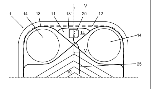
One of the heat exchanger plates 1 is disclosed in Fig 3. The heat
exchanger plate 1 comprises a heat transfer area 10, an edge area
11, which extends around and outside the heat transfer area 10.
The edge area 11 comprises the outer surrounding edge of the
heat exchanger plate 1. The heat exchanger plate 1 also
comprises a gasket path 12, which extends around the heat
transfer area 10 between the heat transfer area 10 and the edge
area 11. A gasket 13 is provided on the gasket path 12 and
extends around and encloses the heat transfer area 10.
The heat exchanger plate 1 may also comprise an additional
gasket path 12', which extends on the edge area 11. An additional
gasket 13' is provided on the additional gasket path 12', see Fig 4.
As can be seen in Fig 4, a space 14 is formed between the gasket
13 and the additional gasket 13'. The space 14 is closed in relation
to the environment and in relation to the plate interspaces 2, 3.
In the embodiments disclosed, four portholes 15 are provided and
extend through the heat exchanger plate 1. The portholes 15 are
located inside and in the proximity of the edge area 11. The
portholes 15 are aligned with the porthole channels 7.
In the embodiments disclosed, the plate heat exchanger is thus
mounted and held together by means of the tie bolts 6 and the
gaskets 13, 13'. It is to be noted, however, that the invention is
applicable also to plate heat exchangers of other kinds. The heat
exchanger plates 1 may for instance be permanently connected to
each other by means of welding, such as laser welding or electron
beam welding, gluing or even brazing. An example of an
alternative mounting of the heat exchanger plates 1, is a so called
semi-welded plate heat exchanger where the heat exchanger
plates are welded to each other in pairs, whereby the pairs of heat
CA 02814804 2013-04-15
WO 2012/053957 PCT/SE2011/051175
8
exchanger plates may be pressed against each other by means of
tie bolts with gasket provided between the plates.
Each heat exchanger plate 1 comprises a communication module
20 comprising an electronic circuit 21, see Fig 5, for instance in the
form of a chip. The electronic circuit 21 is enclosed or embedded
in a casing 22, which protects the electronic circuit 21 from being
affected by external gases and liquids.
The communication module 20 is, in the embodiments disclosed,
provided in the edge area 11. In the edge area 11, the
communication module 20 is properly protected from the media
flowing in the plate interspaces 2, 3 of the plate heat exchanger.
Furthermore, the communication module 20 is in this position
easily accessible from outside, as can be seen in Fig 3. However,
in the variant disclosed in Fig 4, the communication module 20 is
provided in the space 14. In the space 14, the communication
module 20 is enclosed by the gasket 13 and the additional gasket
13', and thus separated also from the environment. The heat
exchanger plate 1 comprises a cut-out 23 in the form of an opening
or recess. The cut-out 23 is provided in the edge area 11, for
instance in the space 14 as can be seen in Fig 4. The
communication module 20 is provided in the cut-out 23, which
provides an advantageous position for the communication module
20. The cut-out 23 may extend to the edge or be provided inside
the edge of the heat exchanger plate 1.
Each heat exchanger plate 1 comprises a device 25, which is
configured to receive or produce a signal. In the embodiments
disclosed the device 25 comprises or consists of a sensor for
sensing a parameter, for instance a temperature sensor, a
pressure sensor or a moisture sensor, and to produce a signal
depending on the value of the sensed parameter. The sensor, or a
sensor probe of the sensor, may be made of an electrically
conducting material in the form of at least a wire, a strip, a foil or a
net. The sensor, or sensor probe, may be attached to or provided
CA 02814804 2013-04-15
WO 2012/053957 PCT/SE2011/051175
9
on the heat exchanger plate 1 in the area where the parameter is
to be sensed, for instance in the heat transfer area 10. The sensor,
or the sensor probe, may comprise an insulating layer which
insulates the sensor, or the sensor probe, from electric contact
with the heat exchanger plate 1.
The device 25 communicates with, and is in the embodiments
disclosed connected to, the electronic circuit 21 of the
communication module 20 so that the signal can be communicated
to or from the device 25. In case of a sensor, the signal is
communicated to the communication module 20.
The communication module 20 also comprises communication
means permitting communication of the signal with a master unit
30 via at least a communication module 20 of another heat
exchanger plate in the plate package. The master unit 30
comprises a processor of any suitable kind. In the embodiment
disclosed the master unit 30 is mounted to the plate heat
exchanger, for instance on the frame plate 4 as indicated in Figs 1
and 2.
The communication means of the communication modules 20 of
the heat exchanger plates 1, and the master unit 30 form or
comprise a communication bus operating according to a suitable
communication protocol. In the embodiments disclosed, the
communication bus is a serial bus. The communication in the
communication bus is initiated, monitored and controlled via or by
the master unit 30.
In the first embodiment, each communication module 20 also
comprises a suitable number of primary contact elements 31
located on a primary side 20' of the communication module 20 and
on a primary side of the heat exchanger plate 1, and secondary
contact elements 32 located on an opposite secondary side 20' of
the communication module 20 and on a secondary side of the heat
exchanger plate 1. In the embodiment disclosed in Figs 5 and 6,
CA 02814804 2013-04-15
WO 2012/053957 PCT/SE2011/051175
the communication module 20 comprises three primary contact
element 31 and three secondary contact elements 32. When the
heat exchanger plates 1 are compressed to each other the primary
contact elements 31 of one of the heat exchanger plates 1 will be
5 in electrical contact with the secondary contact elements 32 of an
adjoining heat exchanger plate 1, as can be seen in Fig 5. In the
first embodiment, the primary contact elements 31 are configured
as spring members ensuring a proper electrical contact with the
corresponding secondary contact elements 32 when the heat
10 exchanger plates 1 are pressed together.
The master unit 30 may comprise corresponding secondary contact
elements 32, which are provided on or extend to the inner side of
the frame plate 4. These secondary contact elements 32 may be
brought into electrical contact with the primary contacts 31 of the
outermost communication module 20 when the plate heat
exchanger is assembled.
In the embodiments disclosed, a first pair of the primary contact 31
and the secondary contacts 32 of one communication module 20 is
provided for a power line 33 for the supply of electric power to the
communication module 20. A second pair of the primary contact 31
and the secondary contacts 32 is provided for a signal line 34 for
the various signals to be transferred. A third pair of the primary
contact 31 and the secondary contacts 32 is provided for a ground
line 35 for connecting the communication module 20 to the ground.
The communication module 20 may comprise only one primary
contact element 31 and only one secondary contact element 32,
wherein the electrical connection to the ground may be provided
via the heat exchanger plates I. The power and signal line may be
combined to a single line, for instance using different current levels
for the power and the signalling. The communication module 30
may also comprise two, four or more primary contact elements 31
and secondary contact elements 32.
CA 02814804 2013-04-15
WO 2012/053957 PCT/SE2011/051175
11
The communication modules 20 are configured be attached or
joined to each other when the heat exchanger plates are arranged
beside each other in the plate package. The casing 22 of each
communication module 20 comprises a surrounding flange 36
extending from the primary side 20' and a surrounding recess 37
on the secondary side 20". When the heat exchanger plates 1 are
pressed together, the recess 37 of one communication module 20,
permits the secondary side 20" of this communication module 20
to be fitted inside the surrounding flange 36 of the adjoining
communication module 20, as can be seen in Fig 5. In such a
manner, a closed space 38 is created between the primary side 20'
of one communication module 20 and the secondary side 20" of
the adjoining communication module 20. The primary contact
elements 31 and the secondary contact elements 32 being in
electrical contact with each other are thus enclosed in the closed
space 38 and protected from the environment. The fitting between
the adjoining communication modules 20 is preferably configured
to be tight to prevent any liquids from penetrating the closed space
38. Advantageously a gasket 39, or any other suitable sealing
member, may be provided between the surrounding recess 37 and
the surrounding flange 36 in order to obtain a proper sealing of the
closed space. According to a further alternative, the casing 22 of
the communication module 20 may be made of a soft flexible
material, such as an elastic polymer material, that provides a
sealing function between the recess 37 and the flange 36.
Signals from each of the devices 25 may thus be communicated to
the master unit 30 via the respective communication module 20
and the communication bus. The master unit 30 is thus configured
to receive and process the signals from the devices 23 of all the
heat exchanger plates I. The master unit 30 may comprise a
display 40 for displaying information to a user, see Fig 1. The
master unit 30 may also comprise means for communication with
other systems, such as an overall control or monitoring system.
CA 02814804 2013-04-15
WO 2012/053957 PCT/SE2011/051175
12
The communication bus, operating according to a suitable serial
communication protocol, is configured to permit the communication
between the device 25 and the master unit 30 via the
communication modules 20. The communication modules 20 are
arranged consecutively after each other, so that the signal is
transferred between the master unit 30 and the communication
module and device 25 concerned via the communication modules
provided between the master unit 30 and the communication
module 20 concerned.
The communication modules 20 are thus consecutively arranged in
the communication bus and have a respective address in the
communication bus corresponding to the position of the
communication module 20 in the plate heat exchanger. In other
words, the order of the communication modules 20 in the plate
heat exchanger determines the address of the respective
communication module 20.
Each communication module 20 comprises a switch member 41,
see Fig 6, which is configured to be open before the
communication bus has been initialised and started, and to be
closed when the communication module 20 is initialised by means
of a signal from the master unit 30. The communication modules
20, or the electronic circuits 21 of the communication modules 20,
are arranged in a daisy-chain circuit.
When one of the communication modules 20 has been initialised,
the switch member 41 of this communication module 20 is closed
so that it is connected to the communication bus and the master
unit 30. The master unit 30 then transfer an initialising signal via
this communication module 20 to the adjoining consecutive
communication module 20 so that this adjoining communication
module 20 is connected to the communication bus and the master
unit 30. This is repeated until no more non-initialised
communication modules 20 answers to the initialising signal. The
master unit 30 now knows in which order the communication
CA 02814804 2013-04-15
WO 2012/053957 PCT/SE2011/051175
13
modules 20 are positioned, and communication module 20 may
thus be identified and addressed by the master unit 30 by means
of its position in the plate package. Consequently, no unique
identification code for each communication module 20 is required,
since the communication bus and the individual communication
modules 20 are automatically configured during initialisation and
start up.
This means that all communication modules 20 may be identical.
Furthermore, this has the advantage that any heat exchanger plate
1 with a communication module 20 may be provided in any position
in the plate heat exchanger, since its address in the
communication bus is automatically given during the initialisation.
As mentioned above, the master unit 30 initiates the
communication bus and gives addresses to the communication
modules 20. Most of the logic signal handling and the alarm
handling may be made in and by the master unit 30. This reduces
the complexity and the costs for the communication modules 20,
and thus for the heat exchanger plates 1. It also reduces the
amount of information to be sent over the communication bus. For
instance, a sensor of the device 25 may communicate only the
actual value of the parameter sensed, while the alarm limit and the
identification of alarm is handled by the master unit 30. In this way
it is easy to change alarm limits. Thanks to the unique address of
each communication module 20, it is possible for the master unit
to tell the operator, for instance via the display 40 or the overall
control or monitoring system, not only that an alarm has occurred,
but also to indicate on which plate the alarm is created.
According to another embodiment, the device 25 comprises a
voltage generator configured to generate a voltage, which may be
applied to the heat exchanger plate 1. Such a voltage may be
applied in order to avoid or remove fouling on the heat exchanger
plates 1, especially in the heat transfer area 10. In this
embodiment, the communication bus is configured to transfer the
CA 02814804 2013-04-15
WO 2012/053957 PCT/SE2011/051175
14
voltage from the master unit 30, or any suitable voltage source
connected to the master unit 30, to the individual communication
modules 20 with the respective heat exchanger plate 1.
In a further embodiment, the heat exchanger plates 1 are double
wall plates formed by two adjoining plates compressed to be in
contact with each other. With such a double wall plate, the device
25, for instance in the form of a sensor of the above mentioned
kind, may be provided between the adjoining plates of the heat
exchanger plate 1.
The present invention is not limited to the embodiments disclosed
but may be varied and modified within the scope of the following
claims.