Note : Les descriptions sont présentées dans la langue officielle dans laquelle elles ont été soumises.
CA 02822582 2013-06-20
WO 2012/090168 PCT/1B2011/055989
THREE-CHAMBERED AUTOINJECTOR
BACKGROUND
TECHNICAL FIELD
[0001] The present invention relates to an autoinjector with three chambers as
well
as to methods of administering medicaments to a human using the three-
chambered
autoinjector.
BACKGROUND
[0002] Autoinjectors have become quite popular and have experienced widespread
use due to a variety of advantages autoinjectors have over typical manual
syringe
injectors. A number of autoinjectors are commercially available, including
EpiPen0
(King Pharmaceuticals Inc.), Anapen0 (Lincoln Medical Ltd.), RebijectO II (EMD
Serono and Pfizer Inc.), and SureClickTM (Amgen). Generally speaking, an
autoinjector is an automatic injection system that is designed to deliver a
medicament into an individual upon activation of a power assembly. Among other
things, autoinjectors generally comprise a housing, a medicament situated
within
the housing, a needle, and a power assembly. After activation of the power
assembly, the needle moves from a storage position in which the needle is
situated
1
CA 02822582 2013-06-20
WO 2012/090168 PCT/1B2011/055989
within the housing to an active position in which the needle extends from the
housing and delivers the medicament to a patient.
[0003] There is a continuing need for improved autoinjector devices.
BRIEF SUMMARY
[0004] In one aspect, the present invention provides a three-chambered
autoinjector.
The autoinjector includes a housing having a forward end and a rear end. In
certain embodiments, the autoinjector further includes an activateable power
assembly, a rear plunger, a first chamber comprising a liquid composition, a
separation assembly, a second chamber comprising a second medicament, a
separation plunger, a third chamber comprising a first medicament, a needle,
and a
bypass within the housing.
[0005] The first medicament is in a liquid form and, preferably, the second
medicament is in a solid form, which can be dissolved in the liquid
composition.
More preferably, the second medicament is in a lyophilized form.
[0006] In an alternative embodiment, both the first and the second medicaments
are
in liquid forms.
[0007] The rear plunger is moveably situated in the housing and is operatively
linked to the power assembly so that after activation of the power assembly,
the
power assembly moves the rear plunger forwardly within the housing. The rear
plunger rearwardly confines the first chamber.
[0008] The separation assembly is moveably situated in the housing and
forwardly
confines the first chamber and rearwardly confines the second chamber. The
2
CA 02822582 2013-06-20
WO 2012/090168 PCT/1B2011/055989
separation assembly comprises a separation assembly bypass having a closed
position in which the separation assembly bypass prohibits the liquid
composition
from flowing through the separation assembly and an open position for allowing
the
liquid composition to flow through the separation assembly and into the second
chamber. After activation of the power assembly, the separation assembly
bypass
moves from the closed position to the open position, allowing the liquid
composition
to enter the second chamber.
[0009] The separation plunger is moveably situated in the housing and
forwardly
confines the second chamber. After activation of the power assembly, the
separation plunger moves forwardly within the housing.
[0010] The third chamber is rearwardly confined by the separation plunger and
comprises a liquid medicament. In addition to the liquid medicament, the third
chamber comprises a gas such as air, so that after activation of the power
assembly,
the gas in the third chamber can be compressed and allow the separation
plunger to
move forwardly within the housing.
[00111 The autoinjector further includes a needle having a needle length, a
forward
end and a rear end. Prior to the activation of the power assembly, the needle
is in a
needle storage position in which the needle is situated within the housing.
After
activation of the power assembly, the needle moves from the needle storage
position
to a needle fully extended position in which the needle reaches a maximal
extension
out of the forward end of the housing.
3
CA 02822582 2013-06-20
WO 2012/090168 PCT/1B2011/055989
[00121A bypass within the housing is forwardly situated with respect to the
separation plunger prior to the activation of the power assembly and the
bypass
forms a bypass area within the housing for receiving the separation plunger.
Prior
to the separation plunger entering into the bypass area, the separation
plunger
creates a seal so as to prevent a solution comprising the liquid composition
and the
second medicament from flowing from the second chamber into the third chamber.
When the separation plunger is received in the bypass area, the separation
plunger
no longer creates a seal between the second chamber and the third chamber and
thus permits a solution comprising the liquid composition and the second
medicament to flow around the separation plunger and into the needle.
[00131The three-chambered design preferably enables all or substantially all
of the
liquid medicament to be delivered to a human as the needle moves from the
needle
storage position to the needle fully extended position and the design enables
a
solution comprising the liquid composition and the second medicament to be
delivered after the needle reaches the needle fully extended position. As a
result, in
a preferred embodiment, the medicaments are delivered at different injection
depths so as to prevent the medicaments from affecting the absorption of one
another in the human's body.
[0014] Another advantage of the present invention is that it allows for the
inclusion
of more storage-stable forms (e.g., lyophilized forms) of medicaments that,
when
stored in liquid form, tend to become less pure, degrade and/or experience
other
unwanted effects.
4
CA 02822582 2013-06-20
WO 2012/090168 PCT/1B2011/055989
[0015] Another advantage is that regulatory provisions in some jurisdictions
may
prohibit the storage of mixed cocktails of multiple medicaments, and the
present
invention provides for separate storage of the medicaments and the mixture of
the
medicaments immediately prior to injection.
[0016] In another embodiment of the invention, a moveable internal medicament
housing has a needle assembly attached to the forward end thereof. Two
separation
assemblies are received in the internal medicament housing and separate it
into
three chambers.
BRIEF DESCRIPTION OF THE DRAWINGS
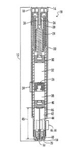
[00171 FIG. 1 illustrates a side cross-sectional view of an autoinjector in a
loaded,
activateable state.
[0018] FIGs. 2-6 illustrate side cross-sectional views of an autoinjector
after
activation of the power assembly.
[0019] FIG. 7 illustrates a side schematic view and a side cross-sectional
view of an
autoinjector needle resting on a concave surface of the separation plunger and
further illustrates the flow of a medicament through the needle.
[00201 FIG. 8 illustrates a top schematic view of an autoinjector needle and
separation plunger.
[0021] FIG. 9 is a side cross-sectional view of an alternative embodiment
having a
moveable internal medicament housing with two separation assemblies received
in
the internal medicament housing.
CA 02822582 2015-02-12
WO 2012/090168 PCT/1B2011/055989
DETAILED DESCRIPTION
[0022] Referring now to the drawings, FIG. 1 illustrates a cross-sectional
view of one
embodiment of an autoinjector generally designated by the numeral 10. In the
drawings, not all reference numbers are included in each drawing for the sake
of
clarity. In addition, positional terms such as "upper," "lower," "side,"
"top,"
"bottom," etc. refer to the apparatus when in the orientation shown in the
drawing.
The skilled artisan will recognize that the apparatus can assume different
orientations when in use.
[0023] Referring further to FIG. 1, the autoinjector 10 comprises a housing 12
having a forward end 14 and a rear end 16. The housing 12 forms the exterior
surface of the autoinjector body and can include one or more structures. For
example, in FIG. 1, the housing 12 comprises a safety pin 18, a cylindrical
body 20
and a needle cover 22. The housing 12, preferably, is generally hollow and can
be
comprised of any material. Preferably, the housing 12 is plastic, but it could
also be
formed from glass.
[0024] Situated within the housing 12 is an activateable power assembly 24.
Power
assemblies for autoinjector devices are well-known to those of ordinary skill
and are
described in, for example, U.S. Patent No. 7,449,012.
Preferably, the power assembly 24
comprises deformable collet arms 26 and a spring 28. In certain embodiments,
the
6
CA 02822582 2013-06-20
WO 2012/090168 PCT/1B2011/055989
power assembly 24 is activated by removing the safety pin 18 and positioning
the
autoinjector 10 on the body of a human. More particularly, in certain
embodiments,
the power assembly 24 is activated by removing the safety pin 18 and pressing
the
forward end 14 of the autoinjector housing 12 against a desired injection site
on a
human's body.
[0025] FIG. 1 shows the autoinjector in a loaded, activateable state ¨ i.e.,
the power
assembly 24 of the autoinjector 10 is capable of being activated, but has not
been
activated and the autoinjector 10 includes a first medicament in a liquid
form, a
second medicament, and a liquid composition so that the autoinjector 10 may
deliver medicaments to a patient. The second medicament is preferably in a
solid
form and the liquid composition is for diluting the second (solid) medicament
This
preferred embodiment will be further described in the rest of the description.
[0026] However, it will be understood that the autoinjector 10 may include a
first
medicament in a liquid form and a second medicament also in a liquid form.
[0027] It will also be appreciated that other states of the autoinjector 10,
for
example, prior to loading with medicaments and the liquid composition or after
activation of the power assembly 24, are also within the scope of the present
invention. For example, FIGs. 2-6 illustrate the autoinjector 10 after
activation of
the power assembly 24.
[0028] Referring further to FIG. 1, the autoinjector 10 further includes a
rear
plunger 30 moveably situated within the housing 12. The rear plunger 30 is
operatively linked to the power assembly 24 so that after activation of the
power
7
CA 02822582 2015-02-12
WO 2012/090168 PCT/IB2011/055989
assembly 24, the power assembly 24 moves the rear plunger 30 forwardly within
the housing 12.
[0029] The autoinjector 10 further includes a first chamber 32 comprising a
liquid
composition. The first chamber 32, and liquid composition contained therein,
are
rearwardly confined by the rear plunger 30. It is also noted that the position
of the
rear plunger 30 relative to the power assembly 24 may be adjusted to adjust
the
volume of the chamber 32.
[0030] The autoinjector 10 further includes a separation assembly 34, which is
moveably situated in the housing 12 and forwardly confines the first chamber
32.
The separation assembly 34 comprises a separation assembly bypass 36, which
has
a closed position in which the separation assembly bypass 36 prohibits a
liquid
composition contained in the first chamber 32 from flowing through the
separation
assembly 34 and an open position for allowing a liquid composition contained
in the
first chamber 32 to flow through the separation assembly 34 and forwardly
within
the housing 12. After activation of the power assembly 24, the separation
assembly
bypass 36 moves from the closed position to the open position, allowing the
liquid
composition to flow from the first chamber 32, through the separation assembly
34
and forwardly within the housing 12.
[0031] Separation assembly bypasses for autoinjector devices are described in,
for
example, U.S. Patent Publication No. 2004/0097874.
8
CA 02822582 2013-06-20
WO 2012/090168 PCT/1B2011/055989
[0032] The autoinjector 10 further includes a second chamber 38 comprising a
solid
medicament. The second chamber 38, and solid medicament contained therein, are
rearwardly confined by the separation assembly 34. In certain embodiments, the
solid medicament is in powder form. Preferably, the solid medicament is a
lyophilized medicament ¨ i.e., a medicament that has been subjected to
lyophilization, otherwise known as freeze-drying. The solid medicament is
referred
to herein as "the second medicament", as it is the second medicament to be
delivered from the autoinjector 10 to a patient.
[0033] The liquid composition included in the first chamber 32 and the second
medicament included in the second chamber 38 are selected so that the second
medicament is soluble in the liquid composition, because, upon opening of the
separation assembly bypass 36, the liquid composition flows into the second
chamber 38 and mixes with, and dissolves, the second medicament so as to
create a
solution comprising the second medicament and the liquid composition.
Preferably,
the liquid composition is an aqueous solution. In certain embodiments, the
liquid
composition included in the first chamber 32 comprises a medicament, thus,
allowing the autoinjector 10 to deliver three medicaments to a patient.
[0034] In addition, in certain alternative embodiments, instead of a
medicament in
solid form, the second chamber 38 can comprise a liquid medicament. In such
embodiments, upon opening of the separation assembly bypass 36, the liquid
composition flows into the second chamber 38 and mixes with the liquid
9
CA 02822582 2013-06-20
WO 2012/090168 PCT/1B2011/055989
medicament in the second chamber 38 so as to form a solution comprising the
liquid
medicament and the liquid composition.
[0035] The autoinjector 10 further includes a separation plunger 40, which is
moveably situated within the housing and forwardly confines the second chamber
38. After activation of the power assembly 24 and after the liquid composition
begins to move through the separation assembly 34 and into the second chamber
38,
the separation plunger 40 moves forwardly within the housing 10.
[0036] The autoinjector 10 further includes a third chamber 42 comprising a
liquid
medicament. The third chamber 42, and liquid medicament contained therein, are
rearwardly confined by the separation plunger 40. The liquid medicament is
referred to herein as "the first medicament", as it is the first medicament to
be
delivered from the autoinjector 10 to a patient. In addition to the first
medicament,
the third chamber 42 comprises a gas which may be air but is preferably an
inert
gas, so that after activation of the power assembly 24, the gas in the third
chamber
42 can be compressed and allow the separation plunger 40 to move forwardly
within
the housing 12.
[0037] The autoinjector 10 further includes a needle 44 having a needle length
45, a
forward end 48 and a rear end 46. As shown, in FIG. 1, the needle 44 is in a
needle
storage position in which the needle 44 is situated within the housing 12.
After
activation of the power assembly 24, the needle 44 moves from the needle
storage
position to a needle fully extended position in which the needle 44 reaches a
maximal extension out of the forward end of the housing 12.
CA 02822582 2013-06-20
WO 2012/090168 PCT/1B2011/055989
[0038] As shown in FIG. 1, preferably, the needle cover 22 comprises a
punctureable
sheath 50 situated over the forward end 48 of the needle 44 so that the needle
44
can puncture through the sheath 50 and extend from the housing 12 after
activation
of the power assembly 24. It is also possible in some embodiments of a triple
chamber autoinjector to have a needle sheath that would be manually removed
prior to use.
[0039] An illustrative needle for use in the present invention is shown in
FIGs. 7
and 8. As shown, the needle 44 comprises a needle base 52, an interior 54, an
exterior 56, a first opening 58 for allowing the first medicament and a
solution
comprising the second medicament and the liquid composition to enter into the
interior 54 of the needle 44 from the housing 12, a second opening 60 for
allowing
the first medicament and the solution to be ejected from the needle 44, and a
passage 62 for allowing the first medicament and the solution to flow through
the
interior 54 of the needle 44 by entering through the first opening 58 and
exiting
from the second opening 60. The needle base 52 preferably rests on, but does
not
cover, a concave surface 64 of the separation plunger 40, which allows the
first
medicament and the solution to flow into an area between the needle base 52
and
the concave surface 64 of the separation plunger 40, enter into the first
opening 58
in the needle 44, through the needle passage 62, and exit from the second
opening
60 in the needle 44. In this embodiment, the first opening 58 of the needle 44
is
located in the needle base 52.
11
CA 02822582 2013-06-20
WO 2012/090168 PCT/1B2011/055989
[00401 However, it will be understood that other embodiments can be used in
the
present invention. For example, the first opening 58 of the needle 44 can be
forwardly situated with respect to the base 52 and can comprise multiple slits
located around the needle 44.
[0041] The autoinjector 10 further includes a bypass 65 within the housing 12.
The
bypass 65 is forwardly situated with respect to the separation plunger 40
prior to
the activation of the power assembly 24 and the bypass 65 forms a bypass area
66
within the housing 12 for receiving the separation plunger 40. The bypass 65
may
be in the form of grooves defined in the housing wall, an enlarged internal
diameter
of the housing wall, ribs extending inward from the housing wall, a cage-like
insert
received in the housing, or any combination of such structures adequate to
permit
fluid to flow around the separation plunger 40 when the separation plunger 40
is
received in the bypass area 66. Prior to the separation plunger 40 entering
into the
bypass area 66, the separation plunger 40 creates a seal so as to prevent a
solution
comprising the liquid composition and the second medicament from flowing from
the second chamber 38 into the third chamber 42. When the separation plunger
is
received in the bypass area 66, the separation plunger 40 no longer creates a
seal
between the second chamber 38 and the third chamber 42, thus, permitting a
solution comprising the liquid composition and the second medicament to flow
around the separation plunger 40 and into the first opening 58 in the needle
44.
[0042] An exemplary mode of operation and method of use is described below for
an
autoinjector loaded with the first medicament, the second medicament, and the
12
CA 02822582 2013-06-20
WO 2012/090168 PCT/1B2011/055989
liquid composition. It will be understood that the method of operation and
method
of use is only exemplary.
[0043] An autoinjector 10 is provided. The autoinjector is in its loaded,
activateable
state. See FIG. 1.
[0044] The safety pin 18 is removed and the forward end 14 of the autoinjector
housing 12 is pressed against a desired injection site on the body of a human.
The
deformable collet arms 26 collapse to release energy from the spring 28. See
FIG. 2.
It is noted that the autoinjector may also be constructed to be activated by a
push-
button rather than by pressing of the autoinjector against the injection site.
[0045] The spring energy causes the rear plunger 30 to begin moving forwardly
within the housing 12. The forwardly movement of the rear plunger 30 decreases
the volume of and pressurizes the first chamber 32. The pressure built up
within
the first chamber 32 causes the separation assembly bypass 36 to move to the
open
position and the liquid composition to flow through the separation assembly 34
and
into the second chamber 38. See FIG. 3.
[0046] The liquid composition begins to dissolve the second medicament to form
a
solution comprising the liquid composition and the second medicament. The
liquid
composition applies pressure on the separation plunger 40, causing the
separation
plunger 40 to move forwardly within the housing 12. The forwardly movement of
the separation plunger 40, in turn, decreases the volume of, and compresses
gas in,
the third chamber 42 and causes the needle 44 to begin moving from the needle
storage position to the needle fully extended position. As the needle 44 moves
from
13
CA 02822582 2013-06-20
WO 2012/090168 PCT/1B2011/055989
the needle storage position to the needle fully extended position, the first
medicament enters into the first opening 58 in the needle, flows through the
passage 62 in the needle 44 and is ejected from the second opening 60 in the
needle
44 and into the body of a human. The rear plunger 30 continues moving
forwardly
and aids the dissolution of the second medicament in the liquid composition.
See
FIG. 4; FIG. 7 (illustrating flow of a medicament through the needle).
[0047] The separation plunger 40 is received in the bypass area 66 and ceases
moving forwardly within the housing 12. The needle 44 reaches the needle fully
extended position and the first medicament ceases flowing through the passage
62
in the needle 44. A solution comprising the liquid composition and the second
medicament flows from the second chamber 38, around the separation plunger 40,
into the third chamber 42, and through the passage 62 in the needle 44. As the
second medicament flows through the passage 62 in the needle 44, the rear
plunger
30 and separation assembly 34 move forwardly within the housing 12. The
forwardly movement of the separation assembly 34 decreases the volume of the
second chamber 38. See FIG. 5; FIG. 7 (illustrating flow of a medicament
through
the needle).
[0048] The rear plunger 30 and the separation assembly 34 cease moving
forwardly
and the solution comprising the liquid composition and the second medicament
ceases ejecting from the needle 44. The delivery of the medicaments is
complete.
Preferably, when the delivery of the medicaments is complete, the volumes of
the
first chamber 32, the second chamber 38, and the third chamber 42 have
14
CA 02822582 2013-06-20
WO 2012/090168 PCT/1B2011/055989
approached zero, which ensures that little to no medicaments remain in the
autoinjector 10 when the delivery of the medicaments is complete. See FIG. 6.
[0049] As mentioned, the design of the autoinjector 10 allows the autoinjector
10 to
administer the first medicament and a solution comprising the second
medicament
and the liquid composition at different injection depths into the body of a
human.
More particularly, due to the seal created by the separation plunger 40 prior
to
entering the bypass area 66, the autoinjector 10 delivers the first medicament
as
the needle 44 moves from the needle storage position to the needle fully
extended
position. The autoinjector 10 delivers a solution comprising the second
medicament
and the liquid composition after the needle 44 moves to the fully extended
position.
It will be appreciated that a small amount of the first medicament may be
ejected
from the needle 44 after the needle 44 moves to the needle fully extended
position,
as the solution comprising the second medicament and the liquid composition
may
wash residual amounts of the first medicament through the needle 44. However,
preferably substantially all of the first medicament is delivered before the
needle 44
reaches the needle fully extended position.
The Embodiment Of Fig. 9
[00501In Fig. 9 an alternative embodiment of the autoinjector is generally
indicated
by the numeral 100. In Fig. 9 parts identical to or analogous to those of the
autoinjector 10 of Fig. 1 are labeled with like numerals.
CA 02822582 2013-06-20
WO 2012/090168 PCT/1B2011/055989
[0051] The autoinjector 100 includes an external housing assembly 102 and a
moveable internal medicament housing 104. The rear plunger 30 and the first
separation assembly 34 are received in the bore of the internal medicament
housing
104. Also received in the internal medicament housing 104 in place of the
separation plunger 40 is a second separation assembly 106, which includes a
bypass
108. A needle assembly 110 includes a needle hub 112 attached to the forward
end
of moveable internal medicament housing 104 for movement therewith relative to
the external housing 102. The needle assembly 110 further includes a needle
116
and a collapsible needle sheath 118.
[0052] The chambers 32, 38 and 42 may contain medicaments and/or liquid
compositions as previously described. A forward end of the third chamber 42 is
preferably sealed by a burstable membrane 114.
[0053] In operation the autoinjector 100 functions generally as follows. The
forward
end of the external housing 104 is placed against a desired injection site on
the body
of the human. A push button actuator 115 is then pressed to release the spring
28.
[0054] The spring energy causes the rear plunger 30 to begin moving forwardly
within the internal medicament housing 104. The bypass 36 of the first
separation
assembly 34 opens and the liquid composition flows from first chamber 32
through
first separation assembly 34 into second chamber 38 and begins to dissolve the
second medicament. Once second chamber 38 fills with liquid composition the
hydraulic pressure applied on second separation assembly 106 will open second
16
CA 02822582 2013-06-20
WO 2012/090168 PCT/1B2011/055989
bypass 108 and will begin moving the entire internal medicament housing 104
and
needle assembly 110 forward.
[0055] The sheath 118 will collapse and the needle 116 will pierce the end of
the
collapsible needle sheath 118 and will extend from the external housing 102 to
its
full insertion depth into the human. The medicament from the third chamber 42
and the dissolved medicament from second chamber 38 will flow substantially
sequentially through the needle 116 into the human at the full needle
insertion
depth.
[0056] Having now described the invention in accordance with the requirements
of
the patent statutes, those skilled in the art will understand how to make
changes
and modifications to the disclosed embodiments to meet their specific
requirements
or conditions. Changes and modifications may be made without departing from
the
scope and spirit of the invention, as defined and limited solely by the
following
claims.
17