Note : Les descriptions sont présentées dans la langue officielle dans laquelle elles ont été soumises.
CA 02823272 2013-06-26
WO 2012/094256 PCT/US2011/068219
METHODS FOR GENERATING SOIL MAPS AND
APPLICATION PRESCRIPTIONS
BACKGROUND
[0001] When planting corn or other crops, a key decision is the spacing
between each
seed. Decreasing spacing increases the overall population (i.e., the number of
seeds per
acre), which increases the number of crop plants in a given area but causes
the plants to
increasingly compete for sunlight and soil resources, reducing the
productivity per plant.
[0002] Modern planters such as that disclosed in U.S. Patent No. 5,956,255
are able to
vary the population while planting and to use a "prescription map" prescribing
a population
(and thus seed spacing) for each location in the field. In planters like that
disclosed in the
'255 patent, an electronic planter monitor receives the planter's current
location in the field
from a GPS receiver and consults the prescription map to determine the
currently desired
population while planting.
[0003] When creating a prescription map to optimize yield, it is desirable
to set different
populations for different soil types and conditions. For example, the optimal
population is
likely higher with more productive soils. Thus in many cases it is desirable
to increase the
population when planting in more productive soils and decrease the population
when planting
in less productive soils.
[0004] In order to identify soil types and productivity in a given field,
services such as the
Soil Data Mart maintained by the United States Department of Agriculture
("USDA")
provide soil data maps such as soil type maps. The soil data maps comprise
sets of polygons,
each of which constitutes the border around each differentiated soil type or
condition. The
vertices of the polygons correspond to a latitude and longitude. Each polygon
is associated
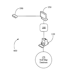
with a data set, which may include the soil type and the estimated yield for
various crops.
[0005] In FIG. 9A, a tractor 920 is schematically illustrated drawing a
variable rate
application implement 926 (e.g., a planter) through a field along a direction
of travel
indicated by an arrow 928. A soil map 900 comprises a polygon 902 having soil
type 2, with
the area outside polygon 902 having soil type 1. The soil map 900 may be
converted to a
prescription map requiring a seed population 2 inside the polygon 902 and a
seed population
1 outside the polygon 902. As the planter 926 moves across the field as shown
in FIG. 9A, it
will plant at population 1 until crossing the boundary into polygon 902, at
which point it
1
CA 02823272 2013-06-26
WO 2012/094256 PCT/US2011/068219
plants at population 2 until exiting polygon 902. Since the planter 926
generally includes
multiple row units arranged transverse to the direction of travel, the row
units are preferably
controlled separately such that, e.g., if the rightmost row unit enters
polygon 902 before the
leftmost row unit, the rightmost row unit will begin planting at population 2
first. As
illustrated in FIG. 9B, the prescription map may also be converted to a raster
image 950
instructing the planter to plant at certain populations in discrete areas or
"rasters" of the same
size.
[0006] Several commercially available software programs assist the user in
creating
planting prescription maps using soil maps and other field data maps. For
example, using
one commercially available farm management program, the user obtains an image
file
containing relevant aerial or satellite imagery and obtains a "shape file"
comprising soil
polygons for a geographical subdivision (e.g., a county) of interest from a
soil data server.
Typical soil data servers will place the user's soil map requests in a queue;
when the user's
request is reached, the soil data server searches for the requested boundary,
creates a
corresponding shape file and alerts the user that the shape file download is
available. Once
the user has obtained the soil map and aerial imagery, such programs display
both images
side by side and allows the user to select corresponding points comprising a
field boundary
on both images. The program then uses the corresponding points to "clip" the
polygons in
the soil map to the field boundary and displays the clipped soil map laid over
the aerial
image. Some farm management software programs additionally allow the user to
import a
field boundary driven and recorded using a global positioning receiver. Once
transferred to
the software, the GPS boundary may be used to clip aerial imagery to the field
boundary.
[0007] Commercially available systems described require multiple complex
steps to
appropriately match field boundaries, aerial imagery and soil data imagery.
Such systems
also require a dedicated software program on the user's computer to perform
the various
operations involved. Due to these inconveniences many users choose to employ
an
agronomy service to generate prescriptions. Thus there is a need for a
simpler, faster and
more intuitive method of generating prescription maps.
DESCRIPTION OF THE DRAWINGS
[0008] FIG. lA schematically illustrates an embodiment of a system for
generating soil
maps and prescriptions.
2
CA 02823272 2013-06-26
WO 2012/094256 PCT/US2011/068219
[0009] FIG. 1B illustrates an embodiment of a process for generating a soil
map and
prescription.
[0010] FIG. 2A illustrates an embodiment of a user interface enabling a
user to navigate
to a field.
[0011] FIG 2B illustrates an embodiment of a user interface enabling a user
to draw a
field boundary.
[0012] FIG 2C-2D illustrate embodiments of a user interface displaying a
soil map and
related soil data and enabling a user to enter a seed population prescription.
[0013] FIG 2E illustrates an embodiment of a user interface allowing a user
to export
seed population prescriptions and soil maps.
[0014] FIG 3 illustrates an embodiment of a planter monitor user interface
displaying a
soil map and prescription and allowing a user to modify a prescription.
[0015] FIG. 4 schematically illustrates another embodiment of a system for
generating a
soil map and prescription.
[0016] FIG. 5 schematically illustrates another embodiment of a process for
generating a
soil map and prescription.
[0017] FIG. 6 illustrates an embodiment of a planter monitor user interface
enabling a
user to record a field boundary.
[0018] FIG. 7 illustrates a preferred an embodiment of a process for
generating a soil
map.
[0019] FIG. 8A illustrates an embodiment of a user interface enabling a
user to add an
external shape to a soil map.
[0020] FIG. 8B illustrates an embodiment of a user interface enabling a
user to create a
prescription based on a soil map and external shapes.
[0021] FIG. 9A illustrates a prior art soil and prescription map.
[0022] FIG. 9B illustrates a prior art raster image.
3
CA 02823272 2013-06-26
WO 2012/094256 PCT/US2011/068219
DESCRIPTION
Prescription Generation Systems
[0023] Referring now to the drawings, wherein like reference numerals
designate
identical or corresponding parts throughout the several views, FIG. 1A
schematically
illustrates a preferred prescription system 100. The prescription system 100
preferably
includes a user computer 120, a planter monitor 150, a data transfer device
180, a global
positioning receiver 190, a user interface 110, a map service 130, a soil data
server 140, a
system server 160, and a system database 170.
[0024] The planter monitor 150 is in electrical communication with the
global positioning
receiver 190. The planter monitor 150 is in data communication with the user
computer 120
preferably through the data transfer device 180 such as a USB or flash drive.
The user
computer 120 is in data communication with the user interface 110 through an
Internet
connection 50. The user interface is preferably accessible using an Internet
browser on the
user computer 120, but may be accessible using a dedicated program stored on
the user
computer 120. The map service 130 and system server 160 provide data to the
user interface
110. The system server 160 is in electrical communication with the system
database 170.
The system server 160 is in data communication with the soil data server 140
through an
Internet connection 50.
[0025] It should be appreciated that although a preferred embodiment is
described as
using Internet connections and data storage devices, the type of data transfer
method or
device between each component is not essential to the prescription system 100.
That is, any
suitable device, system or method may be used to transfer data between
components or to put
the components in communication with one another. In addition, it will be
appreciated that
the functions of the user computer 120 and planter monitor 150 may be combined
into a
single device, and the data stored and retrieved on the various servers may
also be stored on a
single device.
Prescription Generation Methods
[0026] A preferred prescription generation process 200 for using the
prescription system
100 to generate a seed population prescription is illustrated in FIG. 1B. The
user preferably
logs into user interface 110 at step 210 by providing identifying information
such as a
4
CA 02823272 2013-06-26
WO 2012/094256 PCT/US2011/068219
username and password as is known in the art. At step 220, the user interface
110 displays a
map from a map service 130, and enables the user to navigate to the field of
interest by
providing location information through the user interface 110 or by
manipulating the map.
At step 225, the user interface preferably enables the user to enter unique
identifying
information for the field into the user interface 110. At step 230, the user
interface enables
the user to draw a boundary within the field on the map. At step 240, the
system server 160
accesses soil data from the soil data server 140 and generates a soil map
illustrating soil types
within the boundary drawn by the user. The system server 160 also provides
soil data related
to each soil type to the user interface 110, which preferably generates and
displays a table
summarizing the soil data at step 245. The user interface then allows the user
to enter a
desired crop input application parameter, e.g., seed population, for each soil
type at step 250,
resulting in a prescription for the entire field which may be stored in the
system database 170.
At step 252, the user interface enables the user to export the prescription to
a mobile device,
e.g., the planter monitor 150, using the data transfer device 180. During
planting, the planter
monitor 150 determines its location in the field using the global positioning
receiver 190 as is
known in the art and sets the population rate associated with the
corresponding location on
the prescription map.
[0027] The prescription generation process 200 is illustrated further in
FIGs. 2A-2E with
reference to the user interface 110. As illustrated FIG. 2A, the user
interface 110 displays a
map 260 obtained from a map service 130 such as Google Maps or TerraServer.
The map
260 preferably comprises a navigable aerial image map including a layer of
aerial or satellite
images and may additionally include layers identifying street names and other
reference
information. The area displayed on map 260 may be manipulated by the user by
dragging the
map, using a pan control 263 or a zoom control 262 as is known in the art. The
field
selection dialog 280 includes a "New Field" tab 281. Using the New Field tab
281, the user
may enter the location (e.g., city and state or latitude and longitude) of the
field of interest in
location field 282, which preferably results in a request to the map service
130 to display the
desired location. The user may also enter data into a "Client" field 283 and a
"Farm Name"
field 284, and may further enter data into a "Field Name" field 285 such that
the new field is
associated with a specific client and farm for later access by the user. The
user may also
enter data into an expected "Tillable Acres" field 286 of the field. Once the
user selects the
"Draw Boundary" link 287, the system server 160 preferably saves data entered
on the New
CA 02823272 2013-06-26
WO 2012/094256 PCT/US2011/068219
Field tab 281 to the system database and opens a boundary selection dialog 288
illustrated in
FIG. 2B.
[0028] As illustrated in FIG. 2B, a boundary selection dialog 288 instructs
the user to
draw a boundary around the field of interest. The user uses a cursor 294 to
select each vertex
292 of the field, and the user interface 110 displays a resulting boundary 290
connecting the
vertices 292. Once the user returns to and selects the first vertex 292-1, a
field creation
dialog 296 allowing the user to create the field or cancel creation of the
boundary 290. While
the user draws the boundary 290 by selecting additional vertices (e.g., 292-1
through 292-6 as
illustrated), boundary selection dialog 288 preferably displays the latitude
and longitude of
the cursor 294. The prescription system 100 preferably obtains the geographic
locations
(e.g., in latitude and longitude or in GPS coordinates) corresponding to each
vertex of the
boundary 290 from the map service 130 and stores the geographic locations in
the memory of
the computer 120 or in the system database 170. When the user has created a
complete
boundary 290, the boundary selection dialog 288 preferably displays a
calculated field size,
preferably displayed in calculated acreage (539 in FIG. 2C) for comparison
with the expected
tillable acres entered in field 286. The calculated acreage may be determined
using the
distances between the geographic locations corresponding to vertices 292 as is
known in the
art.
[0029] When the user chooses to create the field using the field creation
dialog 296, the
prescription system 100 preferably generates a soil map 560 corresponding to
the extents of
the boundary 290 as illustrated in FIG. 2C. As discussed in further detail
later herein, the
system server 160 obtains soil type polygons and associated soil data
intersecting with or
entirely within the field boundary 290 from a soil data server 140 such as
that maintained by
the Natural Resources Conservation Service ("NRCS"). The soil map 560
comprises the
portions of the soil type polygons within the boundary 290. In FIG. 2C, the
soil map
polygons 561, 562, and 563 have been clipped to the boundary 290.
[0030] At the stage illustrated in FIG. 2C, the user may confirm the
accurate placement of
the boundary by adjusting the transparency of the soil map 560 using
transparency adjuster
549 or by comparing the field calculated acres to the estimated tillable
acres.
[0031] Continuing to refer to FIG. 2C, the user interface 110 preferably
displays a table
in a "Soil Type Rx" tab 565 in a "Create Prescription" dialog 550 displaying
data associated
6
CA 02823272 2013-06-26
WO 2012/094256 PCT/US2011/068219
with each soil map polygon. In the example of FIG. 2C, three management zones
561, 562
and 563 are shown which are associated with respective management zone rows
551, 552,
and 553 in the Create Prescription dialog 550 of the Soil Type Rx tab 565. As
discussed
further below with respect to FIG. 7, it should be appreciated that the soil
map polygons 561-
1 and 561-2 were part of the same soil polygon obtained from the soil data
server that were
split into two separate soil map polygons by the boundary 290, such that both
soil map
polygons 561-1 and 561-2 correspond to the single management zone row 551. As
illustrated, the correspondence of polygons and management zones is preferably
indicated by
hatching or coloring on the user interface 110. The data displayed for each
management zone
row may include estimated yield data 555, acreage data 556, and soil type data
557. It should
be appreciated that multiple categories of soil data may be available for each
management
zone row; the system preferably selects the most relevant data to display
based on a
predetermined preference schedule. Each management zone row 551-553 also
preferably
includes a default population value in population fields 554. In the
illustrated example, the
default population is set at zero, but in other embodiments the default
population could be set
at a non-zero value such as 30,000 seeds per acre.
[0032] As illustrated in FIG. 2D, the user interface 110 also allows the
user to create a
prescription for the field by entering a desired population in the
"Population" field 554 (e.g.,
in seeds per acre) for each soil map polygon by entering a numerical value or
by using
adjustment arrows 541 to adjust the population (e.g., in increments of 500
seeds per acre)
associated with each Population field 554. Once the user has entered at least
one population,
the Create Prescription dialog 550 preferably displays the average population
in the "Average
Population" field 542 representing the calculated average population across
the field. The
user may also enter data in an estimated "Double Plant" percentage field 543
representing the
estimated percentage of the field that will have to be passed over multiple
times. The
prescription creation dialog preferably displays estimated seed units in an
"Estimated Seed
Units" field 544 required for the field, having a value which the system
server 160 calculates
using an appropriate equation, e.g.:
ceed (Anw2g,P)(Argragg Papnnthr4v j::?: ant F,,natzan
(I6 edz, Jnts
, :L!
Where:
"Acreage" is either the calculated acreage or the user-entered tillable
acreage;
7
CA 02823272 2013-06-26
WO 2012/094256 PCT/US2011/068219
"Average Population" is the calculated average population;
"Double Plant Fraction" is the double plant percentage expressed as a
fraction;
"Seeds per Unit" is an estimated number of seeds per storage unit (e.g.,
80,000
seeds per bag).
[0033] Under some circumstances, it is desirable to create multiple
prescriptions for a
single field. As an example, the user may desire to set a prescription for
each hybrid or type
of hybrid that may be planted in the field of interest. Under such
circumstances, the user may
create a new prescription for the same field using drop-down "Attribute" menu
558. In the
illustrated embodiment the Attribute is generically named "Population." When
the user
creates a new prescription, it is created under a user-entered attribute name
(e.g., a hybrid
type such as "flex" or "semi-flex"), the populations entered in Population
fields 554
preferably return to the default value and the user may enter and save new
desired
populations entered in the Population fields 554 for each management zone row
551, 552 and
553. There are several applications in which it is useful to set multiple
prescriptions to the
same field. In the simplest application, the user may not know which hybrid
will be used for
the field while creating prescriptions and the user may choose the appropriate
prescription in
the field once the hybrid has been selected. In a more complex application,
each row unit or
section of row units on the planter that is individually controlled may be
controlled by a
different prescription. Thus the user may plant multiple hybrids in the same
field by
providing different hybrids to various row units and control each row unit
using the
appropriate prescription. It should be appreciated that prescriptions may be
created for other
attributes using the system described herein; for example, a prescription may
be created for a
given hybrid with and without nitrogen application.
[0034] Once the user has entered the prescription and selected the "Save"
liffl( 559, the
user interface 110 preferably displays a prescription "Export" dialog 590 as
illustrated in FIG.
2E. The selection fields 591 allow the user to search only fields
corresponding to the client
and farm of interest. The row corresponding to each field (e.g., "North Field"
in FIG. 2E)
includes a textual export status 594 and an export status icon 592 indicating
whether the field
has been exported. When the user selects the "Export Fields" link 596, the
soil map data is
exported from the user computer 120 to the data transfer device 180.
[0035] Turning to FIG. 3, the user may transfer the soil map data from the
data transfer
device 180 to the planter monitor 150. The planter monitor 150 may comprise a
planter
8
CA 02823272 2013-06-26
WO 2012/094256 PCT/US2011/068219
monitor including features similar to those disclosed in Applicant's co-
pending application
Ser. No. 13/292,384, the disclosure of which is incorporated by reference
herein in its
entirety, and preferably includes a graphical user interface 300 such as a
touch screen display
as well as a central processing unit and a memory. The planter monitor 150
preferably
displays a boundary 290 and soil map polygons 561-1, 561-2, 562 and 563.
Prescription
windows 311, 312, and 313 preferably display the current population, soil
type, and other
data (e.g., a crop productivity index) corresponding to each management zone.
The planter
monitor 150 preferably displays data corresponding to the entire boundary 290
such as "Map
Acres" field 352 and "Average Population" field 354. The planter monitor 150
preferably
allows the user to modify the prescription in the field using, e.g. a touch
screen interface. In
the illustrated embodiment of FIG. 3, the user may use arrows 320 to navigate
between
prescription windows 311-313 and may use prescription adjustment arrows 330 to
adjust the
population for a given boundary in increments of, e.g., 500 seeds per acre.
The user may also
use the "Select All Soil Types" button 325 to select all soil types for
simultaneous adjustment
using the prescription adjustment arrows 330. Once the population has been
altered the user
may select the "Enter" button 360 to save the altered prescription, which may
be exported to
the data transfer device 180 and imported to the user computer 120.
[0036] A preferred method of generating the soil map 260 is illustrated in
FIG. 7. The
steps generally indicated at 750 are preferably performed by the Internet
browser or dedicated
program on the user computer; the steps generally indicated at 760 are
preferably performed
by the system server 160. At step 710, the user interface 110 activates
boundary drawing
tools allowing the user to draw a field boundary 290 over a map 260 as
described above. At
step 715, the Internet browser or dedicated program on user computer 120
preferably
converts the resulting boundary vertices 292 into a document in standard
format readable by
the soil data server, such as a standardized markup language document, e.g.,
an extensible
markup language ("XML") document. At step 720, a request is sent to the soil
data server
140 in order to obtain the soil map polygons that intersect the boundary 290
defined by the
boundary vertices 292. At step 725, a request is sent to the soil data server
140 also for soil
data associated with the polygons obtained at step 720. The requests sent at
steps 720,725 are
preferably a standardized format, e.g., a markup language, readable by the
soil data server.
The process just described with respect to steps 715, 720 and 725 is faster
than requesting an
entire shape file corresponding to a geographical or political subdivision
(e.g., a county)
because such a shape file includes irrelevant soil polygons.
9
CA 02823272 2013-06-26
WO 2012/094256 PCT/US2011/068219
[0037] At step 730, the system server 160 clips the soil map polygons to
the boundary
290. This operation may be performed by using an appropriate application
programming
interface such as JTS Topology Suite, available from Vivid Solutions in
Victoria, British
Columbia, to create polygons that represent the topological or geometric union
between the
boundary 290 and each original soil polygon. It should be appreciated that the
original soil
map polygons returned by the soil data server 140 may extend for miles beyond
the boundary
290; as such, it is advantageous to perform clipping operations on the system
server 160
rather than transferring the original polygons to the user computer 120.
Transferring the
potentially large original polygons to the user computer 120 and using a
potentially less
powerful processor on user computer 120 to perform the clipping operations
requires longer
processing times and likely requires a dedicated program on the user computer
120.
[0038] At step 732, the system server 160 associates each clipped soil map
polygon with
a "management zone." When first obtained from the soil data server 140, each
original
polygon is typically associated with a key or other unique identifier, which
key is also
associated with each article of data pertaining to that polygon. However, a
single polygon
can be converted into multiple polygons after being clipped to a boundary (see
polygons 561-
1 and 561-2 in FIG. 2C). In such cases, the key associated with the original
polygon must be
associated with each resulting polygon. Each polygon associated with the
equivalent unique
identifier (e.g., the same unique key) is preferably identified with the same
management
zone. Thus in FIG. 2C, polygons 561-1 and 561-2 are part of the same
management zone.
[0039] At step 735, the system server 160 preferably attaches the data
(e.g., soil type and
corn yield) associated with each unique key to the corresponding management
zone.
[0040] At step 740, the system server 160 preferably converts the data
returned from the
soil data server to a format usable by a web application platform such as
Adobe Flash, e.g.,
an XML document. At step 745, the Internet browser or dedicated program on
user computer
120 receives the XML document and uses it to create application objects such
as the content
of management zone rows 551-553 discussed above with reference to FIG. 2C. It
should be
appreciated that each management zone row 551-553 corresponds to a management
zone, and
the data illustrated in each management zone row 551-553 (with the exception
of the user-
entered prescription and the calculated acreage of the management zone) is the
data from the
soil data server 140 associated with the same key.
CA 02823272 2013-06-26
WO 2012/094256 PCT/US2011/068219
[0041] At step 747, the user interface 110 sends the latitude and longitude
of the multiple
vector points corresponding to the boundaries of the clipped polygons to the
map service 130,
along with instructions for the color of the polygons. The vector points and
instructions are
preferably compatible with the application program interface provided by the
map service
130. At step 748, the map service 130 generates a map overlay representing the
clipped soil
polygons which is positioned and sized to match the boundary 290 on the map
260. It should
be appreciated that the map service 130 includes a remote map server as well
as an
application program interface provided by the map server that runs on the user
computer 120;
as such, the creation of the map overlay may be carried out either on the
remote map server
or on the user computer 120. It should also be appreciated that as the user
subsequently drags
the map 260 or uses the pan control 263 or the zoom control 262, the map
service 130
updates the map overlay such that the soil polygons remain positioned and
sized to match the
location and scale of boundary 290.
Prescription Generation Methods ¨ Adding External Shapes
[0042] In creating a population prescription, it is sometimes desirable to
set prescriptions
based not only on varying soil types but on other external factors such as
irrigation. Thus the
user interface 110 preferably allows the user to add external shapes such as
irrigation pivots
to the prescription map. As illustrated in FIG. 8A, the "Create Prescription"
dialog 550 may
include "Shapes" tab 810 for adding shapes including links 812 and 814 which
launch
drawing tools to draw full and partial pivots, respectively. When, e.g., the
Draw Full Pivot
liffl( 812 is selected, an instructive dialog 816 is displayed instructing the
user to use the
cursor 294 to draw an irrigation boundary. In the illustrated embodiment, the
user first uses
the cursor 294 to place a center point 817. As the cursor 294 is moved away
from the center
point 817, the user interface 110 displays the circumference of the pivot and
the instructive
dialog 816 displays the calculated area under the pivot. It should be
appreciated that the map
layer 260 may assist the user in selecting the appropriate pivot radius, as
the user is often able
to visually discern the irrigated area from the aerial or satellite imagery.
Once the user has
selected the appropriate location for the pivot circumference, the user
interface 110 creates a
shape 870 representing the pivot area.
[0043] The step of adding a pivot area shape 870 or other external shape
may be
performed before or after the user interface 110 displays the soil polygons
within the
boundary 290. In the example illustrated in FIG. 8A, the pivot area shape 870
has been
11
CA 02823272 2013-06-26
WO 2012/094256
PCT/US2011/068219
added to a soil map including soil polygons 861 and 862. It will be
appreciated that both soil
polygons have portions within the pivot area and outside the pivot area. As
illustrated in
FIG. 8B, a Soil Type Rx tab 565 of the Create Prescription dialog 550
preferably allows a
user to set separate population prescriptions for the portions of each soil
polygon that are
inside and outside the pivot area using an inside pivot prescription field 856
and an outside
pivot prescription field 854.
Monitor-Based Prescription Generation Systems and Methods
[0044] Depending on circumstances and available technology, users may
prefer to create
prescriptions entirely on the planter monitor 150. For these purposes, a
distinct prescription
system 400 for creating a prescription is illustrated schematically in FIG. 4.
The prescription
system 400 includes user computer 120, soil map database 175, data transfer
device 180,
planter monitor 150, and global positioning receiver 190.
[0045] Turning to FIG. 5, a process 500 is illustrated for using the
prescription system
400 to generate a prescription. At step 512, a soil map for a relevant area is
imported to the
planter monitor 150, preferably using the data transfer device 180. The
planter monitor 150
is preferably configured to control the rate of application input, e.g., the
seed population rate.
It should be appreciated that in the process 500, it is necessary to obtain
soil data for an area
larger than the planned field boundary since the exact boundary is not known
when the soil
data is imported to the planter monitor 150. Thus the user may obtain soil
data for an entire
county or other geographical subdivision using user computer 120. Such bulk
data may be
downloaded in shape file format from a soil map database 175 such as that
maintained by the
NRCS.
[0046] At step 510, the user drives the boundary of the field of interest
while the planter
monitor 150 records a series of global positioning vertices reported by the
global positioning
receiver 190, thus recording a filed boundary 290. A preferred display 600 for
guiding the
user through this process is illustrated in FIG. 6. An icon 620 represents the
location of the
global positioning receiver 190. When the user selects the "Record Field
Boundary" button
632, the status bar 612 indicates that the planter monitor 150 is recording
the boundary 290.
A "start of boundary" icon 622 represents the first recorded vertex of the
boundary 290. The
user may pause recording at any time by selecting the "Pause" button 634 and
may preferably
select the Pause button again to resume recording the boundary 290 after
navigating back to
12
CA 02823272 2013-06-26
WO 2012/094256 PCT/US2011/068219
the last recorded location. The indicator 610 reports the distance between the
boundary being
recorded and the physical location of the global positioning receiver 190,
along with an arrow
indicating the direction (preferably from the perspective of the operator
while driving the
tractor) in which the boundary is offset from the global positioning receiver.
Once the user
has returned sufficiently close to the beginning of boundary 290, the user
selects the "End
Field Boundary" button 630 to store the boundary. The boundary 290 may be
saved under a
unique filename using the "Name" field 640.
[0047] Returning to FIG. 5, at step 513 the planter monitor 150 generates a
boundary file
(preferably an XML file) representing the field boundary 290 from the recorded
global
positioning vertices. At step 514, the planter monitor 150 identifies relevant
soil map
polygons intersecting the field boundary. At step 516, the planter monitor 150
generates
management zones; as discussed elsewhere herein, each management zone
corresponds to the
portion or portions of each relevant polygon within the field boundary. At
step 518, the
planter monitor 150 displays a control map comprising the set of management
zones. The
control map preferably includes a default application parameter (e.g., seed
population)
associated with each management zone At step 520, the planter monitor 150
enables the user
to modify the default application parameter using an interface such as
graphical user interface
300 as illustrated in FIG. 3. Once the user has created the prescription, the
control map may
be used to control input application and may be saved to the data transfer
device 180.
[0048] Although the foregoing description describes methods of creating
seed planting
prescriptions, it should be appreciated that the same methods could be used to
generate
spatially dependant crop input prescriptions for any variable rate crop input
such as fertilizer.
Moreover, although the foregoing description describes methods of using a soil
map to create
a prescription, the same or similar methods could be used to generate a
prescription based on
any map of field data. For example, the user could import a yield map
containing polygons
or rasters associated with various yields from a prior year and prescribe
application rates for
each such polygon or raster.
[0049] Additionally, although the methods described herein involve a user
manually
creating a prescription once presented with field data, it is well known in
the art to create
prescriptions using formulae whose inputs include field data. Thus, for
example, the system
could allow the user to specify a formula (or provide a formula) for
converting corn yield into
a population prescription. According to such a method, in the illustration of
FIG. 2C the
13
CA 02823272 2013-06-26
WO 2012/094256 PCT/US2011/068219
prescription system 100 would generate populations for population fields 554
for each soil
map polygon 561, 562 and 563 using an equation that was a function of, e.g.,
corn yield and
factors associated with each soil type and stored in a lookup table.
[0050] The foregoing description is presented to enable one of ordinary
skill in the art to
make and use the invention and is provided in the context of a patent
application and its
requirements. Various modifications to the preferred embodiment of the
apparatus, and the
general principles and features of the system and methods described herein
will be readily
apparent to those of skill in the art. Thus, the present invention is not to
be limited to the
embodiments of the apparatus, system and methods described above and
illustrated in the
drawing figures, but is to be accorded the widest scope consistent with the
spirit and scope of
the appended claims.
14