Note : Les descriptions sont présentées dans la langue officielle dans laquelle elles ont été soumises.
CA 02826857 2013-08-08
WO 2012/107795
PCT/1B2011/001875
1
CLAMP CONNECTION FOR THE ATTACHMENT OF PLATE-SHAPED
COMPONENTS, PARTICULARLY SOLAR MODULES
CROSS-REFERENCE TO RELATED APPLICATIONS
[0001] This
application is a PCT International Application of
European Patent Application No. EP11 001 119.4, filed on February 11, 2011.
The entire disclosure of the above application is incorporated herein by
reference.
TECHNICAL FIELD
[0002] The
present disclosure relates to a clamp connection for the
attachment of plate-shaped components, particularly solar modules, on rail-
shaped carriers provided with guide grooves with margins that protrude inwards
into the groove, consisting of a support with at least one support surface
present
on its upper side, for a component, and with a supporting brace which delimits
the support surface, as well as with a T-shaped counter bearing present on its
lower side, where the crossbars of said counter bearing can be inserted with
alignment in the longitudinal direction of the guide groove in the guide
groove,
and after a rotation by 90 it engages behind the protruding margins of the
guide
groove, and of a clamping cap, with a clamping surface covering the support
surface, and a longitudinal groove which grips the upper part of the
supporting
brace.
[0003] Clamp
connections for the attachment of plate-shaped
components are generally known. However, recently clamp connections for solar
modules have reached a special position. With these clamp connections, it is
especially important that they should be very stable, with a view to very high
mechanical loads generated, for example, due to wind or snowfall, or the size
and the weight of the module. The solar modules should be firmly anchored via
the clamp connections. At the same time, there is the requirement that no
warping due to the clamping should occur on the modules, which can lead to
crack formations on the very sensitive surfaces of the modules.
CA 02826857 2013-08-08
WO 2012/107795
PCT/1B2011/001875
2
BACKGROUND
[0004] For the state of the art, reference is made to DE 20 2008
002 264 U1 and US 2009/0200443 Al. These known clamp connections are not
satisfactory, particularly because they are made up of plurality of individual
parts
which make the required on-site installation expensive. Due to the multitude
of
individual parts, the handling during assembly is difficult, particularly also
because the assembly is made as a rule on carriers that are in an inclined
position. The inclined orientation of the carriers leads to the individual
parts
slipping with respect to each other in an unintended manner, requiring
constant
readjustment.
[0005] In our prior Patent Application EP 09 012 682, an improved
clamp connection has been represented, whose design is simple, and which
allows a facilitated installation. This clamp connection consists
substantially of
three parts: namely a clamp support, a clamping cap, and an attachment screw.
The support has a T-shaped counter bearing on its bottom side, whose base
protrudes from the lower side of the support, and has a crossbar which,
inserted
in the guide groove of the carrier, engages behind the protruding margins of
the
guide groove. In this way, a simplified installation of the clamp support on
the
carrier is possible. The clamping cap is placed on the clamp support, and
screwed to said support by means of the attachment screw. The marginal sides
of the modules are gripped and pressed on the support by the clamping cap. On
the upper side of the support, a supporting brace oriented longitudinally with
respect to the carrier is present, against which the module margin is applied
and
which is provided at the same time as a spacer for the applied modules.
SUMMARY
[0006] The present disclosure is based on the problem of further
improving the clamp connection described in the prior patent application, for
the
purpose of further simplifying its installation, where, at the same time, a
thief-
proof attachment is to be achieved.
[0007] As starting point for the present disclosure, the clamp
connection described in the above-mentioned prior application is used. This
CA 02826857 2013-08-08
WO 2012/107795
PCT/1B2011/001875
3
clamp connection consists substantially of a support with at least one support
surface present on its upper side, for a component, particularly a solar
module,
and of a supporting brace delimiting the support surface or surfaces and
oriented
in the longitudinal direction of the support. On its bottom side, the support
has
the T-shaped counter bearing, which is inserted with its crossbar in the guide
groove of the carrier. The clamping cap has one or more clamping surfaces,
which face the support surfaces on the support, and a longitudinal groove
which
enclose the upper part of the supporting brace. With regard to the support,
the
clamping surfaces are provided laterally with respect to the supporting brace,
namely one on each side, if two solar modules are to be gripped by the clamp
connection. One clamping surface is provided, if the clamp connection is to
grip
only one solar module, which is the case when the solar module is arranged as
an end piece in a row. According to the present disclosure, the clamping cap
and
the support is connected via a latching connection to each other. Thus, for
the
clamp connection, only two individual parts are provided, namely the support
and
the clamping cap. On the clamping cap, the latching pin is arranged,
preferably
by connecting the clamping cap and the latching pin rigidly to form a unit. In
the
support, a bore is provided, into which the latching pin is pushed. Both on
the
latching pin, and also in the bore in the support, sawteeth oriented in
opposite
directions are arranged, which allow pushing the latching pin into the bore,
while
opposing the pulling of the latching pin out of the bore. A screw connection
of the
parts is not needed; the latching pin needs only to be pressed into the bore,
to
attach the clamping cap to the support, and thus simultaneously grip the
margin
of the adjacent solar module. The formation of the latching pin and of the
bore
with sawteeth has the additional advantage that different thicknesses of solar
modules can be gripped by the clamp connection. The sawteeth in the bore and
on the pin, allow the latching pin to be pushed at different depths into the
bore,
so that modules of different thickens can be clamped.
[0008] In many
cases it is advantageous if the clamp connection is
manufactured from a plastic and the support from an elastomer. This allows a
certain elasticity of the clamp connection during the clamping in of the solar
module. In support of said elasticity, the support surfaces can be provided
with
CA 02826857 2013-08-08
WO 2012/107795 PCT/1B2011/001875
4
longitudinal notches. The clamping surfaces of the clamping cap are preferably
provided with a silicone coating, which also has some elasticity.
[0009] To achieve a strong
anti-theft device with the clamp
connection, it is advantageous if in the bore of the support, an insert, made
of a
plastic, for example, is inserted. The latching pin made of plastic and the
insert
made of plastic prevent, to an increased extent, a removal of the clamping
cap.
In this connection, it is also advantageous if the insert is provided with
lateral
brackets, which are applied against the lower side of the crossbar of the
counter
bearing. Finally, it is advantageous if the insert is applied with its lower
margin on
the bottom of the guide groove, and thus generates a resistance of the support
when the latching pin is pushed in.
[0010] For the case where
the clamp connection is provided for
modules of constant thickness, it is advantageous if the latching connection
consists of a latching pin, which has latching lugs at its end, which engage
in
cuts at the lower margin of the bore, or at an undercut in the bore.
[0011] To facilitate the
pressing in of the latching pin into the bore
of the support, the latching pin is provided with at least one longitudinal
slot over
the length of the sawteeth or the latching lugs. By a slight compression of
the
parts of the latching pin which are divided by the longitudinal slots, its
introduction into the bore is facilitated.
[0012] An additional
securing of the clamping cap on the support is
achieved by the fact that the clamping cap on its lower side has longitudinal
notches with back cuts, behind which barbed hooks present on the upper part of
the supporting brace can be clipped in. These barbed hooks extend preferably
over the entire length of the longitudinal notches.
[0013] To reinforce the
strength of the support, the latter can be
provided with a supporting plate, which extends both in the area of the
support
surfaces and also in the area of the supporting brace, and which is embedded
in
the support itself. Both the support plate and also the insert can be inserted
in
the support in a vulcanization process.
CA 02826857 2013-08-08
WO 2012/107795 PCT/1B2011/001875
BRIEF DESCRIPTION OF THE DRAWINGS
[0014] In the appended
drawing, the present disclosure is
represented diagrammatically in several embodiments. The figures show:
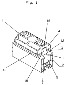
[0015] Figure 1 is an
oblique view of the clamp connection attached
to a carrier;
[0016] Figure 2 is a cross
section through the clamp connection,
with a latching connection via a latching toothing;
[0017] Figure 3 is a cross
section through a latching cOnnection by
means of a latching pin with latching lugs at its lower end;
[0018] Figure 4 is an
enlarged detail of the latching connection
according to Figure 3; and
[0019] Figure 5 is an
enlarged representation of a section of the
clamping cap with the arrangement of the longitudinal notches and the barbed
hooks.
EMBODIMENT OF THE INVENTION
[0020] Figure 1 shows, in
the oblique view, the clamp connection 1
arranged on a partial section of a carrier 2. In the known manner, solar
modules
can be inserted in the clamp connection 1, and clamped therein. The, solar
modules are not shown here in further detail. The clamp connection 1 itself
consists of the support 3 and the clamping cap 4. The carriers 2 are extruded
profiles with a guide groove 5, which has margins 6 and 7 that protrude
inwards.
The support 3 has support surfaces 12 that protrude laterally, and the
supporting
brace 15. The supporting brace 15, with its upper part, lies in the
longitudinal
groove 16 of the clamping cap 4.
[0021] In Figure 2, a cross
section through the middle of the clamp
connection 1 is shown. Here, one can see the support 3 with the support
surfaces 12, the supporting brace 15, the counter bearing 9, and the insert
24,
as well as the clamping cap 4 with the latching pin 18. The latching pin 18 is
pressed into the bore 17 located
in the center in the support 3. The latching pin =
18 has the latching toothing 19, while the latching toothing 20 is provided in
the
bore 17. The latter latching toothing in the present case is located in the
insert
CA 02826857 2013-08-08
WO 2012/107795
PCT/1B2011/001875
6
24. The two latching toothings 19 and 20 are compatible, and consist of
sawteeth oriented in opposite directions. The latching pin 18 is provided,
over
the length that is gripped by the latching toothing, with two longitudinal
slots 21,
which are preferably oriented at a mutual angle of 90 . The longitudinal slots
21
allow a radial compression of the hook arms 22 formed by the longitudinal
slots
21. In the embodiment example, the sawtooth section in the bore 17 of the
support is formed from an insert 24 made of plastic. The counter bearing 9
which
is present on the lower side of the support 3 has a T-shaped design. The base
of the counter bearing 9 comes to be applied beneath the margins 6 and 7 of
the carrier 2, when the T-shaped crossbar lilies in the guide groove 5.
[0022] When the support 3 is applied on the carrier 2, the
clamping
cap 4 is at first oriented transversely to the carrier 2, so that the crossbar
11 can
be inserted in the longitudinal direction into the guide groove 5. After the
introduction of the counter bearing 9 into the guide groove 5, the clamping
cap 4,
and thus also the crossbar 11, is rotated by 90 , so that the clamping cap 4
is
oriented in the longitudinal direction of the carrier 2. The clamping cap 4
itself is
made of a plastic. Its clamping surfaces 13 are provided with a silicon
coating
14. On the surfaces of the support 3, the longitudinal notches 25 are
provided.
These longitudinal notches 25, together with the silicon coatings 14 on the
clamping cap 4, result in a highly resilient, secure clamping in of the solar
modules. The solar modules are thus held in a nondestructive manner between
the clamping cap 4 and the support 3.
[0023] The support 3 is provided in addition with a support plate
41,
which reinforces the strength of the support 3. The support plate 41 and also
the
insert 24 are attached by vulcanization in or on the support 3. The insert 24
has
lateral brackets 26 which are adapted in terms of their shape to the crossbars
11. They are applied on the lower side of the crossbar 11 of the counter
bearing
9, and they are enveloped on their outer sides by the elastomer of the support
3.
The insert 24 is braced with its lower margin on the bottom of the guide
groove
5.
[0024] The clamp connection according to Figure 3, in terms of its
fundamental design, is similar to Figure 2. The latching connection is
different
CA 02826857 2013-08-08
WO 2012/107795 PCT/1B2011/001875
7
here; it consists of a latching pin 48, which is provided with latching lugs
28 at its
lower end, instead of the sawteeth. In the area of the latching lugs 28, the
slots
21 are provided here too in the shape of a cross. These latching lugs 28
engage,
when the latching pin 48 is pressed into the bore 47, into cuts at the lower
margin of the bore 47 or at a back cut in the bore 47. This has the result
that this
ratchet connection is suitable only for a certain thickness of a solar module.
This
thickness is given by the gap, which is predetermined after the engagement of
the latching lugs 28, between the clamping surfaces 13 on the clamping cap 40,
and the support 3. The clamping cap 40 is provided on its lower side with the
longitudinal notches 46 with the back cuts 43. Behind these back cuts 43, the
barbed hooks 44 present on the insert 42 engage, when the clamping cap 40,
and thus the latching pin 48, is pressed into the bore 47.
[0025] For a secure
attachment, in this embodiment, the insert 42
is extended over the entire length of the bore 47, so that the barbed hooks 44
also consist of plastic. At the same time, brackets 50 are present laterally
on the
insert 42, which contribute to the strength of the support 3. A support plate
is not
required here.
[0026] Enlarged detail
embodiments from Figure 3 are represented
in Figures 4 and 5. In Figure 4, one can see the hooking of a latching lug 28
on a
back cut 43 on the insert 42.
[0027] Figure 5 shows in an
enlargement the cross-sectional shape
of a longitudinal notch 46. A ledge-like extension 49, which is present on the
insert 42, can be inserted into these longitudinal notches 46. This extension
49 is
provided with the barbed hooks 44, which engage in a manner so they clip in
behind the back cut 43. As a result, the clamping cap 40 is further secured on
the support 3. The ledge-like top part 49 can easily be deflected sideways
onto
the support 3, during the placement of the clamping cap 40.