Sélection de la langue

Search

Sommaire du brevet 2827667 

Énoncé de désistement de responsabilité concernant l'information provenant de tiers

Une partie des informations de ce site Web a été fournie par des sources externes. Le gouvernement du Canada n'assume aucune responsabilité concernant la précision, l'actualité ou la fiabilité des informations fournies par les sources externes. Les utilisateurs qui désirent employer cette information devraient consulter directement la source des informations. Le contenu fourni par les sources externes n'est pas assujetti aux exigences sur les langues officielles, la protection des renseignements personnels et l'accessibilité.

Disponibilité de l'Abrégé et des Revendications

L'apparition de différences dans le texte et l'image des Revendications et de l'Abrégé dépend du moment auquel le document est publié. Les textes des Revendications et de l'Abrégé sont affichés :

  • lorsque la demande peut être examinée par le public;
  • lorsque le brevet est émis (délivrance).
(12) Brevet: (11) CA 2827667
(54) Titre français: DISPOSITIF DE REGLAGE DE NIVEAU POUR MEUBLES
(54) Titre anglais: FURNITURE LEVELLING DEVICE
Statut: Réputé périmé
Données bibliographiques
(51) Classification internationale des brevets (CIB):
  • A47B 91/02 (2006.01)
  • A47B 9/00 (2006.01)
  • A47B 91/16 (2006.01)
(72) Inventeurs :
  • GILD, KEITH (Afrique du Sud)
(73) Titulaires :
  • GILD, KEITH (Afrique du Sud)
(71) Demandeurs :
  • GILD, KEITH (Afrique du Sud)
(74) Agent: MOFFAT & CO.
(74) Co-agent:
(45) Délivré: 2018-11-20
(86) Date de dépôt PCT: 2012-02-16
(87) Mise à la disponibilité du public: 2012-08-23
Requête d'examen: 2017-02-08
Licence disponible: S.O.
(25) Langue des documents déposés: Anglais

Traité de coopération en matière de brevets (PCT): Oui
(86) Numéro de la demande PCT: PCT/ZA2012/000008
(87) Numéro de publication internationale PCT: WO2012/112996
(85) Entrée nationale: 2013-08-16

(30) Données de priorité de la demande:
Numéro de la demande Pays / territoire Date
2011/00454 Afrique du Sud 2011-02-18

Abrégés

Abrégé français

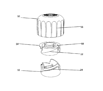
L'invention concerne un dispositif destiné à régler la longueur utile d'un pied de table. Le dispositif comprend des éléments supérieur et inférieur (10, 12, 14) associés l'un à l'autre de façon tournante et sont sollicités dans le sens de l'écartement par des moyens élastiques (20), l'élément supérieur (14) comprenant une première rampe descendante (22) espacée par rapport à une deuxième rampe à rochet (24) associée à l'élément inférieur (12) par une paroi. L'élément supérieur (10) comprend un ou plusieurs cliquets (25) conçus pour circuler dans la rainure entre les rampes (22, 24), et comprenant une formation conçue pour coopérer avec le rochet lorsque la longueur utile souhaitée du pied et du dispositif combinée a été réglée.


Abrégé anglais


The invention provides a device for adjusting the effective length of a table
leg. The device
includes an upper and a lower member (10, 12, 14) that is rotatably associated
with one
another and are biased apart by spring means (20), the upper member (14)
including a first
downwardly directed ramp (22) spaced apart from a second ratchet ramps (24)
associated
with the lower member (12) by a wall. The upper member (10) includes one or
more pawls
(25) adapted to run in the channel between the ramps (22, 24), and including a
formation
adapted to engage the ratchet when the desired effective length of the leg
plus device has
been adjusted.

Revendications

Note : Les revendications sont présentées dans la langue officielle dans laquelle elles ont été soumises.


5
Claims
1. A device for adjusting the effective length of a leg of a table or other
article of furniture, the
device including an upper and a lower member that are rotatably associated
with one another
and biased apart by spring means,
characterised in that the lower member includes at least one first downwardly
directed ramp,
spaced apart from a second upwardly directed ratchet ramp by a wall, to form a
channel,
the upper member including at least one pawl adapted to run in the channel
between the first
and second ramps, the pawl including a formation adapted to engage the ratchet
when the
desired effective length of the leg plus device has been adjusted.
2. A device as claimed in claim 1 characterised in that the pawl includes a
first smooth or curved
zone to provide minimum friction with the first ramp and a pointed zone for
engagement with
the ratchet.
3. A device as claimed in either of claims 1 or 2 characterised in that the
pawl is located on the
inside of the upper member.
4. A device as claimed in claim 3 characterised in that the pawl is integrally
moulded with the
upper member.
5. A device as claimed in any of claims 1 to 4 characterised in that the upper
member includes
two pawls.
6. A device as claimed in any of claims 1 to 5 characterised in that the
device includes an
intermediate member that includes the downwardly directed ramp, and that is
non-rotatable
with the lower member.
7. A device as claimed in any of claims 1 to 6 characterised in that two or
more corresponding
ramps are provided on each of the members.
8. A device as claimed in claim 7 characterised in that three identical and
connecting ramps are
provided in series on each member in the configuration of saw teeth if laid
flat.

Description

Note : Les descriptions sont présentées dans la langue officielle dans laquelle elles ont été soumises.


CA 02827667 2013-08-16
WO 2012/112996 1 PCT/ZA2012/000008
FURNITURE LEVELLING DEVICE
TECHNICAL FIELD OF THE INVENTION
This invention relates to a device for adjusting the effective length of a leg
of a multi-legged
table and particularly a four-or-more legged table; but is also applicable to
other articles of furniture
such as beds, chairs and the like.
BACKGROUND ART
It is a source of annoyance and frustration that tables, in restaurants in
particular, assume a
rocking or wobbling tendency due to irregularities in the floor which cause
one or more of the legs
to lose contact with the floor. Any attempt to overcome this problem by moving
the table is usually
unsuccessful and many diners resort to the use of wads of folded paper, wedges
and the like
under one of the legs that does not contact the floor, which is sometimes
successful but often
results in paper and wedges littering the floor after a while with the
recurrence of the nuisance.
Cam mechanisms have been provided which are actuatable with the foot thereby
to raise or
lower a leg but the perfect position may be lost due to slight movement of the
table or of the
mechanism.
Several attempts to overcome the problem have been proposed using telescoping
legs- for
example Japanese Patent 58206333 but these are complicated, difficult to use
successfully and
aesthetically displeasing.
In US 6920834 each leg is telescoping, the inner tubes having keyways and snap
locking
arrangement in the bottom end of each tube. A dowel pin is provided that is
releasable by
depressing, sliding the outer tube and snapping the dowel pin into a hole when
the length is
correct.
In US6186453 a foot-adjustable leveller has a threaded bolt for upward
insertion into the
end of a leg. A foot is formed at the base with a disc that can be rotated by
foot to raise or lower
the bolt with resulting adjustment of the device.
It is important that the adjusting mechanism is positively locked in the
desired position and
it is also important that the adjusting device is easily operated if the table
is moved. However, as

2
far as the Applicant is aware, even the most sophitticated arrangements to
date have been
unsuccessful in regard to permanency of the adjustment_
In US7290741 a device is described which has an upper and lower members
connected for
relative rotation and each having a ramp in opposing senses so that rotation
causes the ramps to
move over each other to cause raising or lowering of the leg due to the
corresponding expansion
or contraction of the upper and lower members. The friction between the ramps
is beneficial in
maintaining a sort of permanency but it does not provide the permanency to
which the present
invention is directed. Nor does it provide the ease of operation and the
simple arrangement of the
present invention.
A modification of the latter invention is the provision of hydraulic or
pneumatic means to be
located between the upper and the lower members so that a degree of automatic
adjustment is
possible but the hydraulic or pneumatic means tends to be overcome by changes
in the pressure
being applied to the table.
DISCLOSURE OF THE INVENTION
According to the invention a device for adjusting the effective length of a
leg of a table or
other article of furniture includes an upper and a lower member that are
relatively rotatable and are
biased apart by spring means, the upper member being associated with a first
ramp or ramps that
are directed downwards to constitute a wall or walls spaced apart from a
second ratchet ramp/s
associated with the lower member, the upper member including one or more pawls
adapted to run
in the channel between the ramps, the pawl/s including a formation adapted to
engage the ratchet
when the desired effective length of the leg plus device has been adjusted.
The pawl/s may include a first smooth or curved zone to provide minimum
friction with the
first ramp and a pointed zone for engagement with the ratchet. The pawl/s may
be located on the
inside of the upper member and may be integrally moulded therewith.
In a preferred form of the invention the device includes an intermediate
member that
includes the first ramp/s, and that is non-rotatable with the lower member.
It is preferred that two or more corresponding ramps are provided on each of
the members
and in a specific example three identical and connecting ramps are provided in
series on each
member in the configuration of saw teeth if laid flat, as will be explained in
more detail below. GabS
CA 2827667 2018-03-29

CA 02827667 2013-08-16
WO 2012/112996 3 PCT/ZA2012/000008
or passageways are provided to permit the pawls to pass' into the series¨of
channels during
assembly.
BRIEF DESCRIPTION OF THE DRAWINGS
An embodiment of the invention is described below with reference to the
accompanying
drawings, in which:
Figure 1 is an exploded perspective view of a device according to the
invention,
Figure 2 is an angled under view of the partly assembled device,
Figure 3 is an angled side view of Figure 2,
Figure 4 is a sectional side view of the device,
and
Figure 5 is a simulated laid out flat view of the series of channels between
the ramps.
DETAILED DESCRIPTION OF THE PREFERRED EMBODIMENT
The device of the embodiment includes an upper member 10, a lower member 12
and an
intermediate member 14.
The upper member has a larger inside diameter than the intermediate and the
lower
members and is able to be rotated by virtue of the knurls 16. .
The intermediate member has a hollow annulus 18 that receives the lower
portion of a
spring 20 that is accommodated in the upper member as shown in Figure 4. A
series of ramps 22
depend downwardly from the intermediate member and reference is directed to
Figure 5 in this
respect.
The lower member also has a series of ramps 24 that are ratcheted, and
reference is again
directed to Figure 5.
Pawls 25 (only one is visible in Figure 3 and two in Figure 4) extend through
the openings
26 in the intermediate member so that the pawls can be located in the channels
defined between
the ramps 22 of the upper member and 24 of the lower member.
The assembled device is secured into a formation 28 associated with a leg of a
table by
means of a bolt element 30, and the members are joined by means of a nut-and-
bolt (not shown)

4
or other means of joining. It will be appreciated that only one leg of a four-
legged table or other
furniture need to be adjusted and it will also be appreciated that dummy
devices may be provided
for the other three legs for aesthetic purposes.
In operation in the event of the table being unstable due to floor
irregularities, the mass of the
table as exerted through the device thereby causes the pawls to rise out of
the ratchet 24 and to travel
along the ramps 22 of the upper member until the base of the lower portion
contacts the floor when the
pawls will fall into the respective ratchet. If the situation involves a
raised irregularity of the floor the
pawls will be released from the ratchets and move along the ramps 22 to the
position of rest of the
device. Alternatively, or in addition, the upper member may be rotated to
secure the same position.
Referring to Figure 5, the ramps are laid out flat for descriptive purposes.
If the upper
member is rotated the pawl shown will first move from the position 30 to a
position 32 and thence
will fall into the lowermost position in the next channel 34.
CA 2827667 2018-03-29

Dessin représentatif
Une figure unique qui représente un dessin illustrant l'invention.
États administratifs

Pour une meilleure compréhension de l'état de la demande ou brevet qui figure sur cette page, la rubrique Mise en garde , et les descriptions de Brevet , États administratifs , Taxes périodiques et Historique des paiements devraient être consultées.

États administratifs

Titre Date
Date de délivrance prévu 2018-11-20
(86) Date de dépôt PCT 2012-02-16
(87) Date de publication PCT 2012-08-23
(85) Entrée nationale 2013-08-16
Requête d'examen 2017-02-08
(45) Délivré 2018-11-20
Réputé périmé 2020-02-17

Historique d'abandonnement

Il n'y a pas d'historique d'abandonnement

Historique des paiements

Type de taxes Anniversaire Échéance Montant payé Date payée
Le dépôt d'une demande de brevet 200,00 $ 2013-08-16
Taxe de maintien en état - Demande - nouvelle loi 2 2014-02-17 50,00 $ 2014-02-14
Taxe de maintien en état - Demande - nouvelle loi 3 2015-02-16 50,00 $ 2015-01-19
Taxe de maintien en état - Demande - nouvelle loi 4 2016-02-16 50,00 $ 2016-02-15
Taxe de maintien en état - Demande - nouvelle loi 5 2017-02-16 100,00 $ 2017-02-01
Requête d'examen 400,00 $ 2017-02-08
Taxe de maintien en état - Demande - nouvelle loi 6 2018-02-16 100,00 $ 2018-02-14
Taxe finale 150,00 $ 2018-10-05
Taxe de maintien en état - brevet - nouvelle loi 7 2019-02-18 100,00 $ 2019-02-11
Titulaires au dossier

Les titulaires actuels et antérieures au dossier sont affichés en ordre alphabétique.

Titulaires actuels au dossier
GILD, KEITH
Titulaires antérieures au dossier
S.O.
Les propriétaires antérieurs qui ne figurent pas dans la liste des « Propriétaires au dossier » apparaîtront dans d'autres documents au dossier.
Documents

Pour visionner les fichiers sélectionnés, entrer le code reCAPTCHA :


Pour visualiser une image, cliquer sur un lien dans la colonne description du document. Pour télécharger l'image (les images), cliquer l'une ou plusieurs cases à cocher dans la première colonne et ensuite cliquer sur le bouton "Télécharger sélection en format PDF (archive Zip)" ou le bouton "Télécharger sélection (en un fichier PDF fusionné)".

Liste des documents de brevet publiés et non publiés sur la BDBC .

Si vous avez des difficultés à accéder au contenu, veuillez communiquer avec le Centre de services à la clientèle au 1-866-997-1936, ou envoyer un courriel au Centre de service à la clientèle de l'OPIC.


Description du
Document 
Date
(yyyy-mm-dd) 
Nombre de pages   Taille de l'image (Ko) 
Abrégé 2013-08-16 1 15
Revendications 2013-08-16 1 37
Description 2013-08-16 4 149
Page couverture 2013-10-18 1 31
Demande d'examen 2017-10-02 3 188
Paiement de taxe périodique 2018-02-14 1 61
Modification 2018-03-29 8 212
Description 2018-03-29 4 155
Revendications 2018-03-29 1 38
Dessins 2018-03-29 3 40
Abrégé 2018-04-30 1 15
Taxe finale 2018-10-05 1 41
Dessins représentatifs 2018-10-19 1 7
Page couverture 2018-10-19 1 37
Paiement de taxe périodique 2019-02-11 1 59
PCT 2013-08-16 10 447
Cession 2013-08-16 3 94
Taxes 2014-02-14 1 45
Taxes 2015-01-19 1 56
Paiement de taxe périodique 2016-02-15 1 59
Paiement de taxe périodique 2017-02-01 1 58
Requête d'examen 2017-02-08 1 37