Note : Les descriptions sont présentées dans la langue officielle dans laquelle elles ont été soumises.
FIBER OPTIC ADAPTER MOUNT
BACKGROUND
Field of the Disclosure
[0002] The
technology of the disclosure relates to mounts for single fiber and
multiple fiber adapters to allow for the interconnection of connectorized
fiber optic ca-
bles without requiring a fiber distribution terminal, and which may be
positioned on a
wall, in a channel, in a ceiling or beneath molding to facilitate routing of
fiber optic cables
to subscriber premises particularly in multiple dwelling units.
Technical Background
[0003] In the world
of the ever-increasing need for broadband bandwidth optical
cables have become the main part of telecommunication networks. Optical cables
can
transmit voice signals, data signals and video signals for very long distances
with very
high speed. Developments of optic telecommunication networks allow the
connection of
the end user directly to the optical fiber. This kind of network technology
known as
FTTH technology (fiber to the home) requires extending an "all optical"
communication
network closer to the subscribers. As a result such telecommunication networks
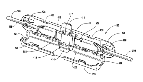
include
large number distribution points from a distribution cable to an end user or
subscriber.
[0004] One of the
key parts of the FTTH network is the last mile connection
which often is an indoor installation. Different kind of buildings like
multiple dwelling
units and blocks of apartments require complicated cabling systems which might
mean
that there are many separated cables, each one to connect one subscriber
premises.
1
CA 2828965 2019-02-01
CA 02828965 2013-08-30
WO 2012/121987
PCT/US2012/027367
Installation of many cables which provide the connection between a main
distribution
point (which usually is located in the basement or in another place of the
building) and
the end user may cause many problems with routing through the wall or levels
of the
building. As a result, such installations consume a lot of time and costs.
SUMMARY OF THE DETAILED DESCRIPTION
[0005] Embodiments
disclosed in the detailed description include a fiber optic
adapter mount having a receiving area for receiving an adapter, a retention
feature and a
mounting feature. The retention feature is configured to releasably retain the
adapter in
the receiving area. The mounting feature is for mounting the adapter mount to
a surface.
One or more resilient walls which may flex to allow the adapter to be received
in and/or
removed from the receiving area. The retention feature may have at least one
tab,
which may extend from one of the one or more resilient walls.
[0006] The
receiving area may be located in the enclosure. The enclosure may
have a base and a cover and the cover may be attached to the base. The cover
may be
hingedly attached to the base allowing the cover to mate with the base and
provide an
open position and a closed positon, and/or a partially open position. Access
may be
provided to an interior of the enclosure whne the cover is in the open
position. The
enclosure may have a connecting feature allowing the fiber optic adapter to be
connected to another fiber optic adapter. The connecting feature may include a
protrusion and /or a groove. The protrusion and groove may be complementary
such
that the protrusion of the fiber optic adapter inserts into the groove of
another fiber optic
adapter to releasably connect the fiber optic adapter to the another fiber
optic adapter.
[0007] Other
embodiments in the detailed description include a fiber optic
adapter mount having an enclosure with an interior, a receiving area, a
retenjtion feature
and a mounting feature. The receiving area is in the interior of the enclosure
is
receiving an adapter. The receiving area may have resilient walls. The
retention feature
may extend from the resilient walls and be configured to releasably retain the
adapter in
the receiving area. The mounting feature may be for mounting the adapter mount
to a
surface. The enclosure may include a base and a cover, and the cover may be
hingedly
movable with the base from an open position to a closed position. An actuator
may
2
CA 02828965 2013-08-30
WO 2012/121987
PCT/US2012/027367
extend from one of the resilient walls. Pressure applied to the actuator may
force the
reslient wall away from another resilient wall allowing the adapter to be
removed from
the receiving area. One or more tie down lance may be formed in the base and
configured to receive a restraining device for restraining fiber optic cable.
[0008] Other
embodiments in the detailed description include an array if fiber
optic adapter mounts including a plurality of fiber optic adapters mounts.
Each fiber
optic adapter mount in the array may include an enclosure, a receiving area,
and a
connecting feature. The enclosure may have an interior, a first section and a
second
section. The receiving area may be for receiving a fiber optic adapter in the
interior.
The connecting feature may allow the fiber optic adapter mounts to be
releasably
connected to each other. The first section or the second section of the
enclosure of at
least one of the fiber optic adapters may be remvobale to allow acces to an
interior of
the enclosure of the fiber optic adapter without disconnecting the fiber optic
adapter
from the array.
BRIEF DESCRIPTION OF THE FIGURES
[0009] FIG. 1 is a
schematic diagram of a perspective view of an exemplary
fiber optic adapter with mounting flanges incorporated into and formed as a
part of the
adapter body;
[0010] FIG. 2 is a
schematic diagram of a perspective view of an exemplary
adapter mount in the form of a mounting clip with a fiber optic adapter
removably
fastened thereto;
[0011] FIG. 3 is a
schematic diagram of a perspective view of an exemplary
adapter mount in the form of a mounting clip and separate snap-on cover with a
fiber
optic adapter removably fastened thereto;
[0012] FIG. 4 is a
schematic diagram of a perspective view of an exemplary
adapter mount having a mounting clip assembly and a integrated living hinge
cover,
with the cover in an open position with a fiber optic adapter removably
fastened to the
mounting clip assembly;
[0013] FIG. 5 is a
schematic diagram of a perspective view of adapter mount of
FIG. 4 with two fiber optic cables, each connectorized with fiber optic
connectors and
3
CA 02828965 2013-08-30
WO 2012/121987
PCT/US2012/027367
with the fiber optic connectors inserted into each end of the adapter to
interconnect the
fiber optic connectors;
[0014] FIG. 6 is a
schematic diagram of a perspective view of adapter mount of
FIG. 4 with the cover in a closed position and the fiber optic cables
extending from
opposite ends of the adapter mount;
[0015] FIG. 7 is a
schematic diagram of a perspective view of an exemplary
fiber optic adapter mount with complementary grooves and protrusions;
[0016] FIG. 8 is a
schematic diagram of perspective views of two fiber optic
adapter mounts of FIG. 7; and
[0017] FIG. 9 is a
schematic diagram of a perspective view of an array of fiber
optic mounts of FIG. 7.
DESCRIPTION OF THE DISCLOSURE
[0018] Embodiments
disclosed in the detailed description include a mount for a
fiber optic adapter. The adapter may be a single fiber adapter or a multiple
fiber
adapter. Additionally, the mount may be integral to and formed as part of the
adapter
body, or, alternatively, may be a separate component to, on or in which the
adapter may
be removably fastened. Further, the mount may include an enclosure providing
environmental protection for the adapter and connectors of the fiber optic
cable
connected thereto. The adapter may be configured to receive one or more fiber
optic
connectors attached to the ends of fiber optic cables to interconnect the
optical fibers of
the fiber optic cables.
[0019] The fiber
optic adapter may be one that provides for multi-fiber
connector to multi-fiber connector interconnection, such as, for example, an
MTP
connector, or OptiTIP connector, as commercially available from Corning Cable
Systems LLC of Hickory, NC, or other types of multi-fiber adapters.
Additionally or
alternatively, the fiber optic adapter may be one that provides for single
fiber connector
to single fiber connector interconncetion, for example an SC connector, LC
connector,
or OptiTAP connector, as commercially available from Corning Cable Systems LLC
of
Hickory, NC, or other types of single fiber adapters.
4
CA 02828965 2013-08-30
WO 2012/121987
PCT/US2012/027367
[0020] Embodiments
disclosed in the detailed description include a fiber optic
adapter mount having a receiving area for receiving an adapter, a retention
feature and a
mounting feature. The retention feature is configured to releasably retain the
adapter in
the receiving area. The mounting feature is for mounting the adapter mount to
a surface.
One or more resilient walls which may flex to allow the adapter to be received
in and/or
removed from the receiving area. The retention feature may have at least one
tab,
which may extend from one of the one or more resilient walls.
[0021] The
receiving area may be located in the enclosure. The enclosure may
have a base and a cover and the cover may be attached to the base. The cover
may be
hingedly attached to the base allowing the cover to mate with the base and
provide an
open position and a closed positon, and/or a partially open position. Access
may be
provided to an interior of the enclosure whne the cover is in the open
position. The
enclosure may have a connecting feature allowing the fiber optic adapter to be
connected to another fiber optic adapter. The connecting feature may include a
protrusion and /or a groove. The protrusion and groove may be complementary
such
that the protrusion of the fiber optic adapter inserts into the groove of
another fiber optic
adapter to releasably connect the fiber optic adapter to the another fiber
optic adapter.
[0022] Other
embodiments in the detailed description include a fiber optic
adapter mount having an enclosure with an interior, a receiving area, a
retenjtion feature
and a mounting feature. The receiving area is in the interior of the enclosure
is
receiving an adapter. The receiving area may have resilient walls. The
retention feature
may extend from the resilient walls and be configured to releasably retain the
adapter in
the receiving area. The mounting feature may be for mounting the adapter mount
to a
surface. The enclosure may include a base and a cover, and the cover may be
hingedly
movable with the base from an open position to a closed position. An actuator
may
extend from one of the resilient walls. Pressure applied to the actuator may
force the
reslient wall away from another resilient wall allowing the adapter to be
removed from
the receiving area. One or more tie down lance may be formed in the base and
configured to receive a restraining device for restraining fiber optic cable.
[0023] Other
embodiments in the detailed description include an array if fiber
optic adapter mounts including a plurality of fiber optic adapters mounts.
Each fiber
optic adapter mount in the array may include an enclosure, a receiving area,
and a
CA 02828965 2013-08-30
WO 2012/121987
PCT/US2012/027367
connecting feature. The enclosure may have an interior, a first section and a
second
section. The receiving area may be for receiving a fiber optic adapter in the
interior.
The connecting feature may allow the fiber optic adapter mounts to be
releasably
connected to each other. The first section or the second section of the
enclosure of at
least one of the fiber optic adapters may be removable to allow access to an
interior of
the enclosure of the fiber optic adapter without disconnecting the fiber optic
adapter
from the array.
[0024] In this
regard, FIGS. 1-6 illustrate exemplary embodiments of fiber optic
adapter mount 100, 200, 300 and 400. FIG. 1 is a schematic diagram of a
perspective
elevation view of the exemplary adapter mount 100. Adapter mount 100 is
integral with
the adapter 10 with a mounting feature 12, which may be in the form of
mounting
flanges incorporated into and formed as a part of the adapter body 14. The
adapter has a
first end 16 and an opposing second end 18 for receiving fiber optic
connectors attached
to the ends of fiber optic cables (not shown in FIG. 1) to interconnect the
fiber optic
cables. Two mounting flanges 12 with mounting apertures 20 are shown in FIG.
1, but
it should be understood that any number of mounting flanges 12 may be
included. A
screw, rivet, push-pin, plunger, or any other type or form of fastener may be
inserted
through the mounting apertures 20 on the mounting feature 12 to attach the
adapter 10
to a mounting surface, as non-limiting examples, on a wall, in a channel, in a
ceiling or
beneath molding.
[0025] FIG. 2 is a
schematic diagram of a front, perspective elevation view of
an exemplary adapter mount 200. In FIG. 2, the adapter mount 200 is the form
of a
mounting clip 202 with a receiving area 204 and a mounting feature 206. The
mounting
feature 206, which may be in the form of mounting flanges which may have
mounting
apertures 208. The receiving area 204 may be at least partially defined by
resilient
walls 210, each of such resilient walls 210 having a releasable retention
feature 212 in
the form of a tab 212. Although FIG. 2 illustrates the retention feature 212
as a tab, any
suitable type of releasable retention feture may be used. When an adapter 10
is inserted
into the receiving area 204 of the adapter mount 200, the pressure of the
adapter 10 on
the retention tabs 212 forces the retention tabs 212 and, thereby, the
resilient walls 210
to spread apart. When the retention tabs 212 and the resilient walls 210
spread apart a
sufficient width, the adapter 10 is allowed to seat within the receiving area
204. The
6
CA 02828965 2013-08-30
WO 2012/121987
PCT/US2012/027367
resiliency of the resilient walls 210 forces the resilient walls 210 back
toward each other
and the retenion tabs 212 position over the adapter 10 removably retaining the
adapter
in the receiving area 204 of the adapter mount 200. To remove the adapter 10,
the
adapter 10 is forced up against the retention tabs 212. When the pressure from
the
adapter 10 is sufficient enough to force the resilient walls 210 apart, the
retention tabs
212 separate enough to not be over the adapter 10, the adapter may be lifted
from the
receiving area 204 and removed from the adapter mount 200. A screw, rivet,
push-pin,
plunger, or any other type or form of fastener may be inserted through the
mounting
apertures 208 on the mounting feature 206 to attach the adapter 10 to a
mounting
surface, as non-limiting examples, on a wall, in a channel, in a ceiling or
beneath mold-
ing.
[0026] FIG. 3. is a
schematic diagram of a front, perspective elevation view of
an exemplary adapter mount 300. The adapter mount 300 has a snap-on cover 302
with
mounting feature 304, which may be in the form of mounting flanges, or the
like, with
mounting apertures 308. The snap-on cover 302 has resilient walls 306 which
spread
apart when the cover 302 is placed over the adapter 10, or alternatively, when
the
adapter 10 is inserted into the cover 10. Once the cover 302 is over the
adapter 10, the
resiliency of the resilient walls 306 applies pressure against the adapter 10
and, thereby,
provides for the adapter 10 to friction-fit or pressure-fit into the cover
302. In this
manner, the adapter 20 is removably retained by the cover 302. Alternatively
or
additionally, the adapter mount 300 may have one or more retention tabs
similar to the
retention tabs 212 described with respect to FIG. 2, and the adapter 10 may be
removably retained in the adapter mount 300 by the retention tabs 212. A
screw, rivet,
push-pin, plunger, or any other type or form of fastener may be inserted
through the
mounting apertures 308 on the mounting feature 304 to attach the adapter mount
300 to
a mounting surface, as non-limiting examples, on a wall, in a channel, in a
ceiling or
beneath molding.
[0027] FIGS 4-6
illustrate and exemplary embodiment of a adapter mount 400
having an enclosure 402 and an integrated living hinge cover 404. In this
regard a
living hinge 420 may connect the cover 404 to a base 406. Instead of a living
hinge 420
some other type of hinge or fastener may be used. The cover 404 may be in an
open
position, a closed position or intermediate or transitioning between an open
or a closed
7
CA 02828965 2013-08-30
WO 2012/121987
PCT/US2012/027367
postion being in a partially open position. When the cover 404 is in an open
position or
a partially open position access may be provided to an interior 403 of the
enclosure 402.
FIG.4 illustrates the adapter mount 400 with the cover 404 in an open position
with the
fiber optic adapter 10 removably retained in the enclosure 402. The enclosure
402 has a
receiving area 408 on the base 406. The receiving area 408 may be at least
partially
defined by resilient walls 410, each of such resilient walls 410 having one or
more
retention tabs 412. When an adapter 10 is inserted into the receiving area
408, the
pressure of the adapter 10 on the retention tabs 412 forces the retention tabs
412 and,
thereby, the resilient walls 410 to spread apart. When the retention tabs 412
and the
resilient walls 410 spread apart a sufficient width, the adapter 10 is allowed
to seat
within the receiving area 408. The resiliency of the resilient walls 410
forces the
resilient walls 410 back toward each other and the retenion tabs 412 position
over the
adapter 10 removably retaining the adapter 10 in the receiving area 408. To
remove the
adapter 10, the adapter is forced up against the retention tabs 412. When the
pressure
from the adapter 10 is sufficient enough to force the resilient walls 410
apart, the
retention tabs 412 separate enough to not be over the adapter 10, the adapter
10 may be
lifted from the receiving area 408 and removed from the adapter mount 400.
Alternatively or additionally, one or more actuators 414 may extend from the
resilient
walls 410. In this regard, pressure may be manually applied to the actuators
414 which
acts to force apart the resilient walls 410 and, thereby, the retention tabs
412. In this
manner, the actuators 414 may be used to insert and/or remove the adapter 10
from the
receiving area 408. The base 406 may have a mounting feature 416, which may be
in
the form of mounting apertures. A screw, rivet, push-pin, plunger, or any
other type or
form of fastener may be inserted through the mounting apertures 416 to attach
the
adapter mount 400 to a mounting surface, as non-limiting examples, on a wall,
in a
channel, in a ceiling or beneath molding.
[0028] Continuing
with reference to FIG. 4 and, also, now to FIG. 5, the
adapter mount 400 is illustrated with two fiber optic cables 500 having
connectors 502
installed in the adapter mount 400 with the connectors 502 received by the
adapter 10 at
each end thereof. The base 406 has one or more tie down lances 418 formed
therein and
configured to receive a restraining device for the fiber optic cable.
Restraining devices
such as tie wraps 426 or other types of restraining device may inserted around
the tie
8
CA 02828965 2013-08-30
WO 2012/121987
PCT/US2012/027367
down lances 418 may be used to restrain fiber optic cable 500 to the base 406
and to
provide strain relief for the cables 500. The cover 404 pivots on one or more
the living
hinges 420 to close on the base 406 (see FIG. 6). The cover 404 has actuator
cutouts
422 aligned with the actuators 414 such that when the cover 404 is closed onto
the base
406 the actuators 414 fit through the actuator cutouts 422. Additionally, the
cover 404
has a cable cutout 424 at each end that aligns with the fiber optic cables 500
extending
from the adapter mount 400 and, thereby, allows for the ingress and egress of
the cables
when the cover 404 is closed on the base 406. One or more fastening tabs 428
on the
cover 404 mate with slots 430 on the base 406 when the cover 404 is closed.
[0029] FIG. 6
illustrates the adapter mount 400 with the cover 404 in the closed
position and with the fiber optic cables 500 extending from opposite ends of
the adapter
mount 400 through the cable cutouts 424. The cover 404 is joined to the base
406 with
the fastening tabs 428 inserted into the respective slots 430 to releasably
retain the cover
404 in the closed position. The actuators 414 are shown extending through the
actuator
cutouts 422. The fastening tabs 428 are sufficiently resilient such that when
pressure is
applied to the cover 404 the fastening tabs 428 to release from the slots 430
allowing
the cover 404 to pivot on the living hinges 420 and move to the open position.
[0030] FIGS. 7, 8
and 9 illustrate embodiments of an adapter mount 600. In
FIG. 7 a single adapter mount 600 is shown having an enclosure 601 defined by
a first
section 602 and a second section 604. The first section 602 may be movably
and/or
removably mounted to the second section 604. Either the first section 602 or
the second
section 604 may act as a base or a cover. The first section 602 and a second
section 604.
are shown mated such that the enclosure 601 of the adapter mount 600 is in a
closed
state. Fiber optic cables 500 extend from the enclosure 601 with the connector
boot 504
external to the enclosure 601 of the adapter mount 600. The adapter mount 600
has a
first end 606 and a second end 608. Connecting feature 609 allows for the
adapter
mount 600 to be releasably connected to another adapter mount 600. In FIG. 7,
the con-
necting feature is shown as protrusions 610 located on opposite sides of the
adapter
mount 600 at the first end 606, and grooves 612.are located on either side of
the adapter
mount 600 the second end 608. The protrusion 610 and the groove 612 are sized
to be
complementary. In this manner, a protrusion 610 on one adapter mount 600 fits
into the
groove 612 of another adapter mount 600.
9
CA 02828965 2013-08-30
WO 2012/121987
PCT/US2012/027367
[0031] In this
regard, FIG. 8 illustrates two adapter mounts 600(1) and 600(2).
In FIG. 8, the first end 606 of adapter mount 600(1) is shown aligned with the
second
end 608 of the adapter mount 600(2). Accordingly, then, the second end 608 of
adapter
mount 600(1) is shown aligned with the first end 606 of the adapter mount
600(2). In
this manner, the protrusion 610 of the adapter mount 600(1) positions near and
may be
inserted into the groove 612 of the adapter mount 600(2). Additionally, the
protrusion
610 of the adapter mount 600(2) positions near and may be inserted into the
groove 612
of the adapter mount 600(1). This allows multiple adapter mounts 600 to be
releasably
connected together.
[0032] FIG. 9 shows
a plurality of adapter mounts 600 releasably connected
together in an array 614. The protrusions 610 of one adapter mount 600 are
positioned
into the grooves 612 of the adjacent adapter mount 600 in the array 614. In
this manner,
adapter mounts 600 may be added to or removed from the array 614.
Additionally, the
array 614 may be mounted or positioned as desired to provide access to the
adapter
mounts 600. Further, as shown in FIG. 9, one of the adapter mounts 600 in the
array
614 is shown with one of the first section 602 or the second section 604
removed to be
able to view the interior of the enclosure 601. Additionally or alternatively,
the first
section 602 and the second section 604 may connect as a base and a cover. In
such a
case, the first section 602 or the second section 604 may open to provide
access to the
interior of the enclosure 601 without disconnecting the fiber optic adapter
mount 600
from the array 614. An adapter 10 is shown mounted in the adapter mount 600
with
connectors 502 of the fiber optic cables 500 connected to either end of the
adapter 10.
[0033] Many
modifications and other embodiments set forth herein will come to
mind to one skilled in the art to which the embodiments pertain having the
benefit of the
teachings presented in the foregoing descriptions and the associated drawings.
Therefore, it is to be understood that the description and claims are not to
be limited to
the specific embodiments disclosed and that modifications and other
embodiments are
intended to be included within the scope of the appended claims. It is
intended that the
embodiments cover the modifications and variations of the embodiments provided
they
come within the scope of the appended claims and their equivalents. Although
specific
terms are employed herein, they are used in a generic and descriptive sense
only and not
for purposes of limitation.