Note : Les descriptions sont présentées dans la langue officielle dans laquelle elles ont été soumises.
CA 02829260 2015-01-16
WALL INSULATION SYSTEM WITH BLOCKS HAVING ANGLED SIDES
BACKGROUND OF THE INVENTION
1. Field of the Invention
[00021 The invention relates generally to the field of constructing buildings.
More specifically, the invention relates to the field of insulating metal
buildings.
2. Description of the Related Art
[00031 Conventionally, metal buildings are constructed according to a series
of
steps. First, a metal frame is constructed. The metal frame includes numerous
structural
support members. The roof portions include sloped roof structural members
referred to as
purlins. The walls include vertically spaced horizontally extending members,
which are
referred to as girts. Once the frame is installed, it is common to insulate
both the roof and
wall portions of the building.
[0004] With respect to roof arrangements, blanket insulation is draped over
the
tops of the purlins, and then roof panels are fastened over the insulation. In
some cases, it
has been known to install a longitudinal thermal block above the top flange of
the purlin
such that it runs the entire length of the purlin over the draped blanket
insulation.
[0005] With respect to the conventional wall, blanket insulation is secured
from
above such that it is draped over horizontally extending girts. Then metal
wall panels are
fastened to the outer flanges of the girts, mashing the blanket insulation
between the wall
panel and the outer flange of each girt where they interface. These lines of
packed-down
insulation create heat losses,
SUMMARY
[00061 The disclosed embodiments include a wall system that is adapted to be
installed onto vertically displaced horizontal support members (e.g., girts)
on a building.
In one embodiment, the system comprises a wall panel having at least one
inwardly-
extending feature (e.g., a ridge or channel). In embodiments, a number of foam
insulation
CA 02829260 2015-01-16
blocks are adapted (on one side) to conform to the shape of the inwardly-
extending
feature. Further, the blocks can be spaced apart (vertically) along each of
the horizontal
support members, and then fastened between the wall panel and the support
members.
The blocks are also spaced apart horizontally which creates an array. The
thickness of the
blocks creates a gap. The gap allows a blanket of insulation to be expanded
into space
created between the blocks.
[0007] In one embodiment, each of the blocks in the plurality has forwardly
angled opposing sides which conform to a reciprocal shape of the feature
(e.g., a ridge)
and a backside that is adapted to be fixed to an outer flange on each girt.
[0008] A method is also disclosed which involves (i) providing a building
structure having a plurality of vertically displaced horizontal support
members; (ii)
obtaining a wall panel having at least one inwardly-extending feature on an
inside surface
of the wall; (iii) conforming the shape of one side of each of a plurality of
insulating
blocks to the inwardly extending feature; (iv) placing the plurality of foam
insulation
blocks between an outside of the horizontal support members and the inwardly-
extending
feature; and (v)fastening the wall to the horizontal support members, thus
sandwiching
the blocks.
[0008a] In one aspect, there is provided a wall system comprising: a plurality
of
vertically displaced horizontal support members; a wall panel having at least
one
inwardly-extending ridge on an inside surface of the wall panel; and a
plurality of foam
insulation blocks, each of the blocks being substantially solid and having
surfaces adapted
to conform to the shape of the inwardly-extending ridge; wherein the plurality
of foam
insulation blocks are spaced apart along each of the horizontal support
members, the
blocks being fastened between the panel and the support members; a blanket of
insulation
expanded between the support members and the blocks into a space laterally
between the
blocks, and wherein the blocks are vertically spaced from one another by a
distance that is
greater than a length of one individual block.
[0008b] In another aspect, there is provided a method of making a wall
comprising: providing a building structure having a plurality of vertically
displaced
horizontal support members; obtaining a wall panel having at least one
inwardly-
extending feature on an inside surface of the wall; conforming the shape of
one side of
each of a plurality of foam insulating blocks to the inwardly extending
feature; placing
the plurality of foam insulation blocks between an outside of the horizontal
support
2
CA 02829260 2015-01-16
members and the inwardly-extending feature, wherein the blocks are vertically
spaced
from one another by a distance that is greater than a length of one individual
block; and
fastening the wall to the horizontal support members, thus sandwiching the
blocks.
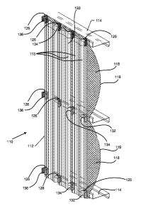
BRIEF DESCRIPTION OF THE SEVERAL VIEWS OF THE DRAWINGS
100091 Illustrative embodiments of the present invention are described in
detail
below with reference to the attached drawing figures:
[0010] FIG. IA shows a cross-sectional wall section of a conventional
insulated
wall panel.
100111 FIG. 1B shows a top view of a horizontal section taken from a
conventional insulated metal building wall design.
[0012] FIG. IC is a broken out section showing the specifics around a girt for
the
conventional design shown in FIGs. 1A and 1B.
[00131 FIG. 1D shows a conventional wall which could be used to accomplish the
objectives of the disclosed embodiments.
[0014] FIG. 2 shows a perspective view of an insulated wall according to the
invention disclosed herein.
2a
CA 02829260 2013-09-05
WO 2012/122510
PCT/US2012/028577
[0015] FIGs. 3A, 3C, and 3D show an angle-edged spacer block from
perspective, above, and in front, respectively.
[0016] FIG. 4A shows a vertical section taken from the insulated wall
of the
present invention.
[0017] FIG. 4B shows a horizontal section taken of the insulated wall
of the
present invention.
[0018] FIG. 4C shows a broken out section taken from the vertical
section of
FIG. 4A.
[0019] FIG. 4D shows a broken out section taken from the horizontal
section
taken from FIG. 4B.
DETAILED DESCRIPTION
[0020] Embodiments of the present invention provide an insulated
metal panel
system for a building, and a method for constructing a metal panel for the
wall of a
building.
[0021] In order to provide a context for the disclosed embodiments,
prior art
drawings FIG. 1A, FIG. 1B, and FIG. 1C show that which is known in the prior
art.
Referring first to FIG. 1A, a conventional system 10 is shown in which a metal
wall panel
12 is installed to create a building wall. This sort of wall panel 12 is
normally fastened to
a plurality of horizontally running and vertically spaced Z-girts 14. The
metal wall panel
12 is typically fastened to the horizontal Z-girt using fasteners 16, which
are typically
self-tapping screws.
[0022] When insulation is desired, a blanket of insulation 18 having
a facing
19 on the inside is typically unrolled, draped down the wall, and then secured
between the
wall panel 12 and the Z-girts 14 using fasteners 16. The fasteners 16 are
screwed into the
outer flange 24 of the girt, as shown in FIG. 1C. The facing 19 prevents
undesirable
contact with inhabitants, presents a more appealing look, and creates a vapor
barrier.
When installed, the insulation is pinched between the inside surface of the
vertical
channels 22. The vertical channels 22, which run up and down the wall 12, are
the
innermost part, meaning that they extend towards the building interior the
furthest (See
FIG. 1B). Between each of these channels, an outermost raised portion 20 of
the wall 12
also extends uniformly in a vertical direction. It is through the channel area
22 of the wall
3
CA 02829260 2013-09-05
WO 2012/122510
PCT/US2012/028577
12 that the fasteners 16 are driven, then through the insulation blanket 18,
then into the
girt outer flange 24.
[0023] Looking at the exploded view in FIG. 1C, it can be seen that
when the
fastener 16 is screwed through the inner portion 22 of the wall it presses
against the
outermost flange 24 of the girt 14 sandwiching a portion 26 of the insulation.
[0024] The compacting of insulation 18 in area 26 causes significant
heat
losses. As those skilled in the art will recognize, the mashing down of
blanket creates an
area where the thermal resistance is weakened. Because of this, if one were to
look at
heat flow diagrams in the areas near the outer flange of the girt, they would
see
significant flow of heat energy through the area surrounding the fastener 16,
with the heat
losses being reduced at the locations spaced above or below the girt outer
flanges. This is
because the insulation 18 (e.g., half way between the girts in FIG. 1A)
billows and fluffs
outward the further it is from the sandwiching girt outer flanges 24. And
considering that
the insulation blanket is pinned between the inside surface of the channel 22
and the girt
outer flange 24 at numerous locations in the panel 112, the heat loss
resulting would
appear as a plurality of vertically displaced parallel horizontal stripes of
heat loss on the
outside of each so-configured wall of the building.
[0025] The arrangement of the present invention 110 which can be seen
in
FIGs. 2 through 4 greatly reduces the heat losses in the metal wall 112. As
with the
conventional system, the metal wall 112 is attached outside of the girts 114
of the
building using fasteners 116. Also like with the conventional systems a
blanket of faced
insulation 118 is draped down, and installed between the wall and the girt 114
when the
wall is mounted. Also like with the conventional systems, the insulation
blanket has a
facing 119 on the inside of the insulation. Further, the new system 110, like
conventional
system 10, is fastened at the innermost channel portions 122 of the wall 112.
[0026] But the new system 110 is different in that the outer flanges
of the girt
124, upon fastening of the wall panel 112, are not directly pressed against
the blanket
insulation 118. Instead, a plurality of foam spacer blocks 126, each having
forwardly
angled opposing sides, are intermittently fastened between the wall 112 and
girt outer
flange 124 along the length of the girt 14.
[0027] As can be seen in FIG. 4A, spacer blocks 126 are spaced
vertically by
a considerable distance 128. Distance 128 is far greater than the lengthwise
dimension of
each block allowing for significant vertical spacing between blocks. Also,
laterally, the
4
CA 02829260 2013-09-05
WO 2012/122510
PCT/US2012/028577
spacer blocks 126 (as can be seen in FIG. 4B) are laterally spaced a distance
130. This
creates significant thermodynamic advantages in that the spacer blocks 126,
since they
are constructed of insulating foam, thermodynamically isolate and displace the
metal wall
panel 112 from the girt. The lateral dimension of each block is significantly
less than the
horizontal distance 130 between the blocks, this distance 130 being dictated
by the
distance between the ridges/channels 122 on the wall panel 112. See FIG. 2.
Further, the
blanket insulation 118 is only pinched against the girt outer flanges 124 in a
few spread-
apart locations. Thus, the blocks 126, in addition to providing thermal
resistance, also
serve to space the wall apart from the girt outer flange. This creates more
area for the
blanket insulation to billow out (fluff) into, and also prevents the heat loss
from extending
nearly the full distance of the girt outer flange, as happens in the
conventional designs
like that shown in FIGs. 1A-C..
[0028] Details of the spacer block 126 can best be seen in FIGs. 3A-
D.
Referring first to FIG. 3A, it can be seen that each spacer block 126 has a
front face 302
(see FIG. 3C) and two opposing angled front faces 304. Laterally, spacer block
126 has
sides 306 which extend back to two rear portions 308 which are created by
truncating the
back portions of the block at converging angles, and then a rear face 310.
FIG. 3D shows
the back of the block 126. A top 312 of the block 126 can be seen in FIG. 3B
and is
pointed to in both of FIGs. 3C and 3D. Although it is not shown, the bottom of
block 126
is the same as the top 312, and the block 126 is symmetrical from side to
side, and top to
bottom.
[0029] As can best be seen in FIGs. 2 and 4C-D, these blocks 126 are
specially configured to fit inside between the inside ridge surfaces of the
channel/ridge
portions 122 of the wall and the girt outer flange 124. More specifically,
face 302 will
butt against the ridge of the channel 122, and the angled sides 304 will
correspond to the
sloped surfaces of the channel 122 so that the block fit inside the wall is
true. On the
other side of the block 126, the back 310 will butt against the girt outer
flange 124 when
the wall is fastened.
[0030] Each of the blocks 126 has a thickness dimension (between
faces 302
and 310). Because of this, the placement of the blocks (in the array shown in
FIG. 2)
results in a gap between innermost portions of the wall (e.g., the ridges) and
the outer
flanges 124 of the horizontal support members 114. This enables the expansion
of the
blanket of insulation into the gap created.
CA 02829260 2015-05-29
[0031] In terms of assembly in the erection of the building, the girts
114 will
already be in place as shown in the figures, and the remaining wall components
will be
installed outside them. In some embodiments, the blanket insulation 118 will
be draped
over the outsides of the gins 114. It is not necessary to independently fasten
the
insulation 118 at this point, but in may instances it will make sense to
secure the blanket
118 from above and allow it to drape down before fastening the wall onto the
girts 114.
The next step, in embodiments, involves the securement of the blocks in some
way. In
some embodiments, this would mean that the blocks would be adhered or in some
other
way fastened to the inside surfaces (ridges) of the wall in the positions
shown before the
wall is fastened in place. The precise position for adhering each block 126
will be
determined by spacing the horizontal rows of blocks 126 at the vertical
positions of each
horizontally extending girt (see FIG. 2). This enables the user with all of
the blocks 126
adhered, to place the panel 112 over the draped insulation 118 and hold the
panel 112 in
place. Then, each fastener 116 (e.g., self-tapping screw) can be screwed
through the
panel 112 outside of where each block 126 exists, through the block, and bite
into the girt
outer flange 124. Once all of the fasteners 116 have been installed, the
panel/block
assembly will be secured to the building, hut significant open space will be
created by the
distance between the panel 112 and the girt 114. The blocks 126 create this
space. This
space created not only allows for more fluffing of the insulation 118 between
the girts
114, but also allows for the fluffing into the spaces created between the
blocks along the
girt flange.
[0032] Fluffed blanket insulation is considerably more effective as a
heat
barrier than insulation that is matted down. Thus, a much higher percentage of
the wall
panel 112 is backed by insulation which is billowed rather than matted down.
Therefore,
as opposed to the conventional system shown in FIG. 1, heat losses are greatly
reduced by
use of the blocks. Also, in the FIGs. 2-4 embodiments where there is no
fluffed
insulation behind the wall, the foam insulation blocks 126 exist. Thus, a high
level of
heat resistance is provided across the whole panel after it is installed,
unlike the
[0033] The scope of the claims should not be limited by particular
embodiments set forth herein, but should be construed in a manner consistent
with the
specification as a whole.
6
CA 02829260 2015-05-29
[0034] Not all steps
listed in the various figures need to be carried out in the
specific order described.
7