Note : Les descriptions sont présentées dans la langue officielle dans laquelle elles ont été soumises.
= CA 02832370 2014-03-27
54106-1485
1
Axial bearing device having increased iron filling
FIELD OF THE INVENTION
The present invention relates to an axial bearing device
having an annular electrical sheet arrangement in which the
individual sheets protrude radially outward, and an electrical
coil which is inserted into the electrical sheet arrangement
in order to generate a magnetic field in the electrical sheet
arrangement.
BACKGROUND
Active, magnetic axial bearings are used in order to set
defined spacings between two objects in contactless fashion.
The basic construction of such an axial bearing can be seen in
FIG 1. In the example a shaft 1 is mounted in axial fashion. A
steel disk 2 is attached concentrically on the shaft 1. In
addition to the steel disk 2 the axial bearing arrangement
here has two annular electromagnets 3, 4 (here also referred
to as axial bearing devices) which are arranged on both sides
of the steel disk 2 coaxially therewith and with the shaft 1.
While the electromagnets 3 and 4 are static and are attached
for example on the housing of an electrical machine, the shaft
including the steel disk 2 rotates in the interior of the two
electromagnets 3, 4.
The electromagnets 3, 4 exert forces on soft magnetic
materials such as the steel disk 2. When the electromagnets 3,
4 are suitably controlled, the steel disk 2 can be held in
contactless fashion at a defined axial position between the
electromagnets 3 and 4.
The electromagnets 3, 4 are as a rule constructed using
torroidal cores which are arranged in a groove in an iron
CA 02832370 2014-03-27
54106-1485
2
support. The iron support is usually of solid construction. In
solidly constructed supports field changes result in eddy
currents which in turn produce opposing fields. The
controllability of the magnetic bearings is thereby degraded.
Eddy currents are reduced in a known manner through lamination
of the support iron. The lamination of axial bearing supports
is known from the publication DE 691 03 756 T2 where the
stator and rotor components of a magnetic thrust bearing are
described with each having a laminated design. The lamination
sheets are curved such that their tips lie in a common
cylindrical plane. In addition, side edges abutting one
another of the lamination sheets likewise lie in common planes
which are arranged perpendicular to the axis of rotation.
An electromagnetic device for a fuel injection pump is known
from EP 0 795 881 Al. The stator of the electromagnetic device
comprises a plurality of electrical sheets which are arranged
in spiral form around the center axis of the stator.
SUMMARY
The object of some embodiments of the present invention
consists in improving the degree of efficiency of the magnetic
axial bearing device.
There is provided a magnetic axial bearing device having
- an annular electrical sheet arrangement wherein the
individual sheets protrude radially outward and adjacent
sheets form a gap in the circumferential direction, and
- an electrical coil which is inserted into the electrical
sheet arrangement in order to produce a magnetic field in
the electrical sheet arrangement, wherein
- the electrical sheet arrangement has at least two
concentric electrical sheet rings and
CA 02832370 2014-03-27
54106-1485
3
- essentially all the adjacent sheets of each electrical
sheet ring meet at the inner circumference of the
respective electrical sheet ring.
An annular electrical sheet arrangement of a known
construction type has sheets which extend continuously from
the inner circumference to the outer circumference of the
electrical sheet arrangement. Since the electrical sheets have
the same width throughout and abut one another at the inner
circumference, correspondingly large gaps between adjacent
sheets result at the outer circumference. This means that the
iron filling of such a type of annular electrical sheet
arrangement is not very high. In an advantageous manner
therefore according to some embodiments of the present invention the
electrical sheet arrangement is divided into at least two concentric
electrical sheet rings. With regard to each electrical sheet
ring the electrical sheets extend in each case from the inner
circumference to the outer circumference. Since even in the
case of the outermost of the at least two electrical sheet
rings the electrical sheets now abut one another at the inner
circumference thereof a higher iron filling can be achieved
because in the case of the conventional electrical sheet
arrangement the individual sheets are distinctly spaced apart
at the radial height of the inner circumference of the
outermost electrical sheet ring of the arrangement according
to some embodiments of the invention.
By preference the electrical sheet arrangement has three
concentric electrical sheet rings, in which case the middle
one of the electrical sheet rings forms.a depression into
which the electrical coil is inserted. In this situation it is
particularly advantageous if the middle electrical sheet ring
has the same radial width as the inserted electrical coil. The
CA 02832370 2013-10-04
PCT/EP2012/054385 / 2011201335W0
4
axial bearing device is thereby designed to be simple to
manufacture.
In addition, an opening can be arranged in the axial direction
in the middle electrical sheet ring for feeding through cables
for the electrical coil. This has the advantage that the
connecting lines for the electrical coil can take the shortest
possible route to the outside, in which case the magnetic
circuit is only minimally disrupted.
In a preferred embodiment the electrical sheet arrangement is
accommodated in an annular pot. The pot stabilizes the
electrical sheet arrangement in both radial directions and in
an axial direction.
The electrical sheet arrangement can be retained in the pot by
means of one or more retaining rings. By this means the
electrical sheet arrangement is also fixed with respect to the
open side of the pot.
If such a retaining ring is designed to have a T-shaped cross-
section, it can retain the innermost and also the outermost
electrical sheet ring in the axial direction in form-locked
fashion in the pot. Two electrical sheet rings are thereby
fixed axially by means of a single retaining ring.
Furthermore, the middle electrical sheet ring can be retained
in form-locked fashion in the pot by means of the innermost
and outermost electrical sheet rings. The entire electrical
sheet arrangement, which here consists of three electrical
sheet rings, can thereby be fixed in the pot by means of a
single retaining ring which, as mentioned above, is for
example designed to have a T-shape.
81773901
According to a further preferred embodiment the interstices
between the sheets of the electrical sheet arrangement are
filled with a resin. This stabilizes the individual sheets with
respect to one another and thereby the entire electrical sheet
5 arrangement and at the same time ensures the necessary
electrical insulation.
Particularly advantageously, an electrical machine can be
equipped with such an axial bearing device. The magnetic axial
bearing ensures minimal friction losses.
According to one aspect of the present invention, there is
provided a magnetic axial bearing device, comprising: an
annular electrical sheet arrangement having individual sheets
which protrude radially outward, with adjacent sheets forming a
gap in a circumferential direction, said electrical sheet
arrangement having at least two concentric electrical sheet
rings, with essentially all the adjacent sheets of each
electrical sheet ring meeting at the inner circumference of the
electrical sheet ring; and an electrical coil inserted into the
electrical sheet arrangement for producing a magnetic field in
the electrical sheet arrangement, wherein the electrical sheet
arrangement has three concentric electrical sheet rings, with a
middle one of the electrical sheet rings having a depression
for insertion of the electrical coil.
According to another aspect of the present invention, there is
provided an electrical machine, comprising a magnetic axial
bearing device including an annular electrical sheet
arrangement having individual sheets which protrude radially
outward, with adjacent sheets forming a gap in a
CA 2832370 2018-06-15
81773901
5a
circumferential direction, said electrical sheet arrangement
having at least two concentric electrical sheet rings, with
essentially all the adjacent sheets of each electrical sheet
ring meeting at the inner circumference of the electrical sheet
ring, and an electrical coil inserted into the electrical sheet
arrangement for producing a magnetic field in the electrical
sheet arrangement, wherein the electrical sheet arrangement has
three concentric electrical sheet rings, with a middle one of
the electrical sheet rings having a depression for insertion of
the electrical coil.
BRIEF DESCRIPTION OF THE DRAWINGS
The present invention will now be described in detail with
reference to the attached drawings. In the drawings:
FIG 1 shows an axial bearing according to the prior art;
FIG 2 .. shows a top view of a section of an electromagnet
from FIG 1;
FIG 3 shows a top view of an electrical sheet arrangement
of an annular electromagnet;
FIG 4 shows an enlarged view of a section from FIG 3 and
FIG 5 shows a cross-sectional view through the
electromagnet from FIG 2 without a coil.
DETAILED DESCRIPTION
The exemplary embodiments described in detail in the following
constitute preferred embodiments of the present invention.
CA 2832370 2018-06-15
81773901
5b
For example, a generator or another electrical machine has an
axial bearing, as is illustrated in principle in FIG 1. The
electromagnets 3 and 4 of the axial bearing, in other words of
the axial bearing arrangement, have a construction according to
the invention, as is demonstrated in detail in the following.
The construction is simple and results in a high
CA 2832370 2018-06-15
CA 02832370 2014-03-27
54106-1485
6
iron filling and a robust combination.
FIG 2 shows a top view of a section of an electromagnet 3, 4
(axial bearing device). The electromagnet 3, 4 has an annular
pot 5, only the concentric walls 6, 7 of which can be seen in
FIG 2.
The annular pot 5 is filled with a laminated innermost ring 8
and a laminated outermost ring 9. Between the two rings is
situated a torroidal core 10. As will be explained in
connection with FIG 5, the innermost ring 8 together with the
outermost ring 9 and a middle ring form an annular groove
beneath the coil 10, into which the torroidal core 10 is
inserted.
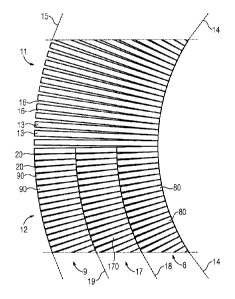
The special nature of the lamination of the annular
magnet can be seen from FIG 3. A conventional lamination 11
can be recognized in the upper half of FIG 3. The lower half
of the laminated ring on the other hand exhibits the
lamination 12 described herein.
FIG 4 shows an enlarged section of the ring from FIG 3. The
differences between conventional lamination 11 and lamination
12 described herein can be better recognized there.
Normal electrical sheets are used here for the laminations.
They all have the same thickness.
With the conventional lamination 11 and also with the
lamination 12 described herein the individual sheets
protrude radially outward. A star-shaped electrical sheet
arrangement thereby results in each case. For explanatory
purposes the entire annular electrical sheet arrangement is
illustrated with two different laminations 11 and 12. In
CA 02832370 2014-03-27
54106-1485
7
practice, one electrical sheet arrangement will naturally only
have one of said two laminations across the entire
circumference.
With the conventional lamination 11, each individual sheet 13
protrudes in the radial direction from the inner circumference
14 as far as the outer circumference 15. Since the individual
sheets 13 abut one another directly at the inner circumference
14, on account of the star-shaped construction a relatively
large gap 16 results in each case at the outer circumference
15 between adjacent sheets 13. The iron filling of a ring
laminated in suchlike manner is correspondingly low.
With the lamination 12 described herein, at least
two concentric electrical sheet rings, in the present example
three electrical sheet rings, are provided, namely the
innermost electrical sheet ring 8, the outermost electrical
sheet ring 9 and the electrical sheet ring 17 situated
therebetween. In the schematic FIG 3 and FIG 4 the individual
electrical sheet rings 8, 9 and 17 each have the same radial
thickness. As can already be seen from FIG 2 however, the
radial thicknesses of the individual rings can be different.
In particular they can, as is likewise explained in connection
with FIG 5, also protrude radially into one another.
The lower half of FIG 4 illustrates that the individual sheets
80, 90 and 170 are radially shorter than the sheets 13 of the
conventional lamination 11. The sheets 80 of the innermost
electrical sheet ring 8 are also not formed in one piece with
the sheets 90 and 170 of the outermost electrical sheet ring 9
and the middle electrical sheet ring 17. The sheets 90 are
likewise not formed in one piece with the sheets 170. This
then has the advantage that the individual sheets 80, 90 and
CA 02832370 2013-10-04
PCT/EP2012/054385 / 2011P01335W0
8
170 can abut one another at the respective inner circumference
or inner radius 14, 18, 19 in the case of each of the
electrical sheet rings 8, 9 and 17. This means that the iron
filling at the inner circumferences 14, 18, 19 is 100% in each
case and it reduces slightly towards the respective outer
circumference of the corresponding electrical sheet ring 8, 9,
17. Since the individual sheets 80, 90, 170 do not however
extend from the inner circumference 14 of the innermost
electrical sheet ring 8 as far as the outer circumference 15
of the outermost electrical sheet ring 9 the gap 20 between
for example adjacent sheets 90 in the circumferential
direction is significantly smaller than a respective gap 16 in
the case of conventional lamination 11. The reason for this is
the fact that the outermost electrical sheet ring 9 has
considerably more sheets 90 than the middle electrical sheet
ring 17. The latter in turn has significantly more sheets 170
then the innermost electrical sheet ring 8. The innermost
electrical sheet ring 8 has equally as many sheets 80 as the
electrical sheet arrangement having conventional lamination
11.
With the three concentric electrical sheet rings 8, 9 and 17 a
significantly higher iron filling can be achieved than in the
case of conventional lamination 11. The axial force attained
is proportional to the iron filling. The increase in force is
determined from the ratio of the iron fillings. For an
electrical sheet arrangement having a single ring, an iron
filling fl results. In the case of an electrical sheet
arrangement having three concentric electrical sheet rings of
the same radial thickness, an iron filling f3 results. The
corresponding ratio of the iron fillings is then:
f3/f1 = 1 + s/(3r1) where s corresponds to the radial thickness
and ri to the inner radius of the electrical sheet arrangement.
CA 02832370 2013-10-04
PCT/EP2012/054385 / 2011P01335W0
9
Increases in force of 10% to 20% thereby result with regard to
typical construction sizes of electromagnets or axial bearing
devices.
FIG 5 illustrates a section of the cross-section through an
axial bearing device according to the invention. In
particular, the pot 5 with its U-shaped cross-section, its
outer wall 6 and its inner wall 7 can be clearly recognized.
The laminated innermost ring 8 nestles against the inner wall
7. The outermost laminated ring 9 abuts on the outer wall 6.
The middle electrical sheet ring 17 is situated between the
two electrical sheet rings 8 and 9. The lamination of the
individual rings 8, 9, 17 cannot be seen in FIG 5.
The two electrical sheet rings 8, 9 extend in the axial
direction 21 from the base 22 of the annular pot 5 up to the
top edges of the walls 6, 7. The middle electrical sheet ring
17 on the other hand extends significantly less far in the
axial direction 21. This means that a groove 23 (which is
however not included in the drawing in FIG 5) for the
torroidal core 10 is produced axially above the middle
electrical sheet ring 17 and between the outermost electrical
sheet ring 9 and the innermost electrical sheet ring 8.
Located axially below the middle electrical sheet ring 17 here
is a retaining ring 24 which has a T-shaped cross-section and
is attached by means of screws 25 on the base 22 of the
annular pot 5. The radially protruding arms of the retaining
ring 24 with its T-shaped cross-section grip above shoulders
26 and 27 of the innermost electrical sheet ring 8 and the
outermost electrical sheet ring 9. The two electrical sheet
rings 8, 9 are thereby fixed in the pot 5.
CA 02832370 2013-10-04
PCT/EP2012/054385 / 2011P01335W0
The two electrical sheet rings 8, 9 furthermore have grooves
28, 29 running in the circumferential direction, into which
projections of the middle electrical sheet ring 17 protrude.
The middle electrical sheet ring 17 is thereby retained in
form-locked fashion (in relation to the axial direction 21)
between the innermost electrical sheet ring 8 and the
outermost electrical sheet ring 9. The three electrical sheet
rings 8, 9 and 17 can thus be retained in the pot 5 by means
of a single retaining ring 24. In principle, however, it is
also possible to provide a plurality of retaining rings for
attaching the electrical sheet rings.
Even if the above examples are embodied with three concentric
electrical sheet rings, the electrical sheet arrangement can
also consist of only two concentric electrical sheet rings or
also of four and more electrical sheet rings. In the case of
two electrical sheet rings, one half of the middle electrical
sheet ring illustrated in FIG 5 would then for example be
connected in one piece with the outermost electrical sheet
ring and the other half in one piece with the innermost
electrical sheet ring.
The torroidal core 10 requires cable feeds. To this end,
appropriate openings or cable outlets can be provided in the
axial direction in the electrical sheet arrangement and also
the pot 5. In the example shown in FIG 5 the pot 5 has an
opening 30 for this purpose in its base 22. Since the
electrical sheet arrangement has three electrical sheet rings
in this case, the middle electrical sheet ring 17 can be
simply interrupted at the point corresponding axially with the
opening 30. The retaining ring 24 would likewise need to be
interrupted here, which can also be seen in FIG 5. The
innermost and outermost electrical sheet rings 8, 9 remain
CA 02832370 2014-03-27
54106-1485
11
closed however. With regard to one-piece lamination, further
disadvantages result here compared with multi-part lamination
because the lamination needs to be interrupted at the cable
outlet, which means that the respective sheets are no longer
able to protrude outward. Otherwise, a substantial amount ,of
extra work is required in order to create an opening for the
connecting lines.
In order to increase the mechanical strength, the interstices
between the sheets of the electrical sheet rings can be filled
with resin.
In an advantageous manner the axial bearing device according
to some embodiments of the invention, acting as a support, has an
increased iron filling compared with known devices, which results in a
correspondingly higher force density. The concentric =
. arrangement having a plurality of rings moreover results in a
robust construction which can be manufactured cost-
effectively.
. .1
=